RESEARCH OUTPUTS / RÉSULTATS DE RECHERCHE
Author(s) - Auteur(s) :
Publication date - Date de publication :
Permanent link - Permalien :
Rights / License - Licence de droit d’auteur :
Bibliothèque Universitaire Moretus Plantin
Institutional Repository - Research Portal
Dépôt Institutionnel - Portail de la Recherche
researchportal.unamur.be
University of Namur
A Code Tagging Approach to Software Product Line Development
Heymans, Patrick; Boucher, Quentin; Classen, Andreas; Bourdoux, Arnaud; Demonceau,
Laurent
Published in:
International Journal on Software Tools for Technology Transfer (STTT)
Publication date:
2012
Document Version
Early version, also known as pre-print
Link to publication
Citation for pulished version (HARVARD):
Heymans, P, Boucher, Q, Classen, A, Bourdoux, A & Demonceau, L 2012, 'A Code Tagging Approach to Software Product Line Development: An Application to Satellite Communication Libraries', International Journal
on Software Tools for Technology Transfer (STTT), no. 5, pp. 553-566.
General rights
Copyright and moral rights for the publications made accessible in the public portal are retained by the authors and/or other copyright owners and it is a condition of accessing publications that users recognise and abide by the legal requirements associated with these rights. • Users may download and print one copy of any publication from the public portal for the purpose of private study or research. • You may not further distribute the material or use it for any profit-making activity or commercial gain
• You may freely distribute the URL identifying the publication in the public portal ? Take down policy
If you believe that this document breaches copyright please contact us providing details, and we will remove access to the work immediately and investigate your claim.
(will be inserted by the editor)
A Code Tagging Approach to Software Product Line
Development
?
An Application to Satellite Communication Libraries
Patrick Heymans1,2, Quentin Boucher1, Andreas Classen1??, Arnaud Bourdoux3, Laurent Demonceau3
1 PReCISE Research Centre, University of Namur, Belgium, e-mail: {phe,qbo,acs}@info.fundp.ac.be 2
INRIA Lille-Nord Europe, Universit Lille 1 – LIFL – CNRS , France
3
Spacebel S.A., Li`ege Science Park, Belgium, e-mail: {arnaud.bourdoux,laurent.demonceau}@spacebel.be
The date of receipt and acceptance will be inserted by the editor
Abstract. Software product line engineering seeks to systematise reuse when developing families of similar software systems so as to minimise development time, cost and defects. To realise variability at the code level, product line methods classically advocate usage of inher-itance, components, frameworks, aspects or generative techniques. However, these might require unaffordable paradigm shifts for developers if the software was not thought at the outset as a product line. Furthermore, these techniques can be conflicting with a company’s coding practices or external regulations.
These concerns were the motivation for the industry-university collaboration described in this paper in which we developed a minimally intrusive coding technique based on tags. The approach was complemented with traceability from code to feature diagrams which were exploited for automated configuration. It is supported by a toolchain and is now in use in the partner company for the development of flight grade satellite communica-tion software libraries.
Key words: Software Product Line Engineering – Code Tagging – Feature Diagrams – Automation
1 Introduction
Software product-line engineering (SPLE) is an increas-ingly popular software engineering paradigm institution-alising reuse across the software lifecycle. Clements et al.[12] define a software product line (SPL) as “a set of software-intensive systems that share a common, man-aged set of features satisfying the specific needs of a
? Extended version of [9] ?? FNRS Research Fellow
particular market segment or mission and that are de-veloped from a common set of core assets in a prescribed way”. By adopting SPLE, one expects to achieve mass-customisation, i.e., the ability to create many different systems, leveraging on similarities between them and thereby improve the cost, productivity, time to market and quality of developing software.
Current approaches to the implementation of SPLs classically advocate usage of specific programming tech-niques (e.g., via inheritance, and aspects [1,3,4,6,17, 40]), particular architectures (e.g., components or dedi-cated frameworks [17,21]), preprocessor directives (e.g., ifdefdirectives in C [17,36]), adapted IDEs (e.g., syn-tax colouring [16,19,26]) or generative programming [13]. One thing almost all of these approaches have in common is the paradigm shift they require in the way software is written. While the transition from ‘classical’ software engineering to SPLE is generally a conscious decision, known to have a major impact on project management, drastic changes to the development approach may prove unaffordable. Whether or not a paradigm shift is the best solution heavily depends on the context which it-self is made of many factors: regulations, company stan-dards, skills of the developers, the intended evolution of the software. . . In the case of safety-critical software, as for instance flight-grade satellite software, it can be out-right impossible to change the coding paradigm, since it is part of the mission requirements and often enforced by external regulations (e.g., [34]). As we will see, this is actually the case in the industrial context that motivates the research described in this paper.
A major challenge for SPLE is to maintain trace-ability between low-level implementation artefacts and high-level abstractions, namely the features of the sys-tem, so as to facilitate variability management. Indeed, the choice of which product of the SPL is going to be built is generally expressed in terms of high-level fea-tures. If there is no traceability from features to
imple-mentation artefacts, then product derivation cannot be automated, possibly negating the expected benefits of adopting SPLE.
These concerns were the main motivations for a col-laboration between the University of Namur and an in-dustrial partner, Spacebel S.A., a software company spe-cialized in aerospace applications. The context of this work, which we now describe in more detail, is the de-velopment of a family of file transfer protocol libraries. 1.1 Industrial context
The CCSDS File delivery Protocol (CFDP) [10], is a file transfer protocol for communication links spanning interplanetary distances. Figure 1 shows a sample us-age scenario of the protocol in which a Spacecraft and a Network Control Centreexchange files through a Ground Station. It also shows a Remote User using the CFDP protocol to communicate with the Spacecraft through its connection with the Network Control Centre.
The protocol was issued by the Consultative Com-mittee for Space Data Systems (CCSDS). It is indepen-dent from the underlying file system and is meant to cover an extensive number of mission needs. Capabili-ties include deferred transmission (if the communication link is unavailable, the transfer will be performed at the next transmission opportunity), concurrent transfer, sus-pend/resume, and the ability to transmit via a proxy (a rover communicating via an orbiter with the ground sta-tion).
Components for space usage are developed in order to deal with extreme environmental conditions such as cosmic rays, temperature variation and vibration. This type of hardware is thus generally very expensive and several evolutionary steps behind consumer hardware. As a consequence, very stringent restrictions apply to suppliers of on-board software components. CPU usage and memory footprint are typical quantities that have to be minimised. For such developments, practitioners often have no other choice than programming in C and obey-ing strict rules that prohibit usage of ‘dangerous’ mech-anisms (typically, dynamic heap memory allocation) or general-purpose third-party libraries. Similar constraints apply to development tools which have to be certified by the appropriate authorities. For example, Spacebel uses the Rhapsody CASE tool and a certified C compiler.
Considering these restrictions, and given that specific missions only require part of the protocol’s functional-ity, it is highly desirable to only deploy those parts of the protocol that are eventually going to be used. More con-cretely, the feature set of a CFDP implementation has to be minimal wrt. the mission requirements: the im-plementation cannot include dead code, i.e., code that cannot be executed by any of the selected features. The SPLE approach described in this paper takes these con-straints into account.
Ground Station Frame/CLTU
Service Network Control Centre
CFDP Entity Packet Service TCP Spacecraft CFDP Entity Packet Service Frame Service Remote User CFDP Entity TCP Legend :
CFDP user Communicationlink
Fig. 1. A CFDP scenario (adapted from [10])
1.2 Problem statement and contribution
The objective of the collaboration between the univer-sity and Spacebel was to jointly develop an SPL im-plementation technique that would satisfy the following requirements:
(R1) Allow mass-customisation of the CFDP library, i.e., be able to efficiently derive products that only contain features required for a specific mission, such that no product has dead code.
(R2) Have a minimal impact on current development practices (see Section 1.1), and be compliant with quality standards and regulationsin place for flight software.
(R3) Automate the solution as much as possible, i.e., automate product derivation and verification de-pending on selected options.
The approach that came out of this collaboration consists of a tool-supported process that spans from fea-ture modelling (i.e., capturing the commonalities and variabilities between the intended products of the CFDP SPL) down to compilation. For the implementation we chose a pruning-based approach, i.e., there is one com-plete code base which contains all features of the system, and from which optional features can be stripped out. At the code level, this is achieved by special annotations, called feature tags, which trace code fragments back to features.
Our approach is supported by a toolchain which, as required, automates the constraints verification and code generation tasks behind a user-friendly interface. As we shall see, strict adherence to R2 in particular leads to a rather pragmatic approach to SPL implementation, that is easy to learn, easy to apply and does not cause much overhead. It has been used with success by the industry partner for the development of the CFDP library prod-uct line, and has now become integral part of their core development method base.
The remainder of the paper is structured as follows. We first provide the necessary background on SPLE and feature diagrams in Section 2. The overall approach is introduced in Section 3. In Section 4, we then focus on
Software
pus snd_min recv_min extended reboot
recv_min_excl recv_inactivity recv_min_ack recv_reception
_oppor
recv_usr_ proxy_put recv_fs
recv_keep_
alive recv_asynch_nak
recv_prompt_ nak recv_suspend_ resume recv_immediate _nak ... ... ... ... ... ... ... ... ... ... ... ... <<excludes>> Level 1 Level 2 Level 3
Additional Constraints Legend
Sof tware =) snd min _ recv min extended =) snd min ^ recv min
and decomposition or decomposition optionalf eature
Fig. 2. Partial FD of the CFDP library
a central component of this approach, namely code tag-ging. The deployment of the process in the company is described in Section 5 and evaluated in Section 6. Fi-nally, Section 7 reviews related work and Section 8 con-cludes the paper.
Henceforth, “we” refers to the team consisting of the two partners: the university and the company.
2 Feature models
Central to the SPLE paradigm is the modelling and man-agement of variability, i.e. “the commonalities and dif-ferences in the applications in terms of requirements, architecture, components, and test artefacts” [37]. This variability is often conveniently expressed in terms of fea-tures, which appear to be high-level abstractions that shape the reasoning of the engineers and other stake-holders [11]. A product of the SPL is seen as a set of features. In the case of the CFDP library, an example of a feature is the ability for a user to act as a sending entity (snd min). This feature, in turn, can be further decomposed: the sender can work in acknowledged mode or not, snd min ack, and so on.
Feature diagrams (FDs) [22, 39] are popular means to model the variability of an SPL in terms of features. An FD describes all legal combinations of features, each combination being the specification of a product of the SPL. One of the typical usages of FDs is to guide the configuration (a.k.a. product derivation) process [14].
A partial FD for the CFDP library is shown in Fig-ure 2. Basically, FDs are trees whose nodes denote fea-tures and whose edges represent top-down hierarchical decomposition of features. The features on level 1 rep-resent the main functionality of the library: send (the snd min feature) and receive (recv min) files, allow for a device to receive data through others (extended ), safe reboot after unexpected system failure (reboot), and sup-port for the “packet utilisation standard” (pus). Each is then further decomposed on one or two more levels, as shown for the recv min feature.
Feature
Modelling Design Implementation
Domain engineering
Configuration and compilationCode pruning
Application engineering
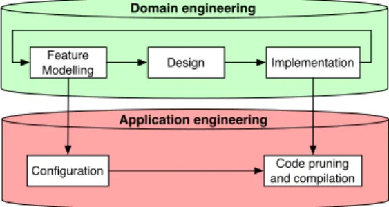
Fig. 3. Process overview
In addition to their tree-shaped backbone, FDs can also contain cross-tree constraints, often specified in propo-sitional logic [5] or a subset thereof. The excludes rela-tionship between features recv min excl and recv min ack in Figure 2 is an example of such a constraint. Indeed, if the protocol is to support the acknowledged transfer mode, then the code required for unacknowledged trans-fer mode only cannot be included. Additional textual constraints at the bottom of the figure are another ex-ample: a valid implementation of the protocol needs to have at least sending or receiving capability, and if it is to serve as a proxy (the extended feature), it needs to have both.
In the process we present in the next section, FDs are used to specify the commonality and variability of the SPL as well as for product derivation.
3 Overall process
Before providing the details of the code tagging approach and its integration with FDs, we set the stage with an overview of the proposed process. What follows is not meant to be a complete development process, but rather an adaptation or complement to a development process in place. The various activities may well be performed independently or in a different order depending on the settings. Their purpose is to help achieving the require-ments set out in the introduction.
The proposed process is represented graphically in Figure 3. It is organised according to the classical SPLE process [37] which consists of two main streams: do-main engineering(the creation of reusable artefacts) and application engineering (the usage and adaptation of reusable artefacts to create final products). During do-main engineering, a set of core assets is developed: in our case the FD, the system architecture, and the tagged code. Application engineering starts with a configuration step during which features are selected or deselected. This selection is then used to remove dead code before compilation. This produces a particular product of the SPL.
Feature modelling One of the first steps is to capture the variability of the SPL, i.e. to identify features and their
relationships to each other. In the case of the CFDP product line, Spacebel actually based this analysis on the official protocol specification [10]. In a more clas-sical software engineering scenario, this step will most likely be based on a requirements specification. Although this step precedes design and implementation, the latter steps may lead to revisions of the FD, hence the feedback loop in Figure 3.
Design As in classical software development approaches, the goal here is to define the (high- and low-level) ar-chitecture of the system. The FD has to be taken into account during this phase because the architecture must facilitate implementation of the variability. To this end, designs (typically UML diagrams) have to be annotated with features, allowing us to trace features from specifi-cation to design. It is also at this step that whole pack-ages, files and functions that are needed for a specific feature will be identified.
Implementation In an effort to be minimally intrusive, implementation must remain largely untouched. Yet, we need to trace features down to their implementation. The approach we developed for this purpose is a form of code tagging. It is detailed in Section 4. Roughly, during the implementation, programmers annotate the code with tags that designate the various features of the CFDP library.
In the course of a project, the implementation may lead to changes of the FD. This commonly happens if it turns out, for example, that a feature decomposition was too fine-grained, or if new dependencies surface. Configuration Configuration consists in selecting the fea-tures to be included in a particular product. This phase is generally guided by the requirements of a particular customer or mission. It is important that the resulting product is valid, i.e. that it respects all constraints of the FD. This validity check can be done manually but is then tedious and error-prone. Hence we recommend using a tool dedicated to variability management (see Section 5).
Code pruning and compilation Up to this point, the im-plementation contains all possible features. The last step thus consists in removing non selected features from the tagged source code. This part is also specific to the sug-gested code tagging approach detailed in the next sec-tion. Roughly, a feature parser takes as input the com-plete program together with a list of selected features, and returns a program containing only the code frag-ments pertaining to the selected features. The resulting source code can then be compiled normally.
Taken together, configuration, code pruning and com-pilation correspond to what is usually called “product derivation” in SPLE.
4 Tag and prune
One can distinguish between two types of approaches for implementing SPLs: compositional approaches im-plement features as distinct modules while annotative approaches assume that there is one complete code base where annotations in the source code indicate the feature a fragment belongs to [23,26]. With the compositional approach, a product is generated by composing a set of fragments. With an annotative approach, a product is obtained by removing fragments corresponding to dis-carded features.
We decided to follow an annotative approach since in our case compositional approaches come with a paradigm shift, which would violate one of our three main require-ments, viz. minimal change of the coding practice. In addition, compositional approaches tend to be coarse-grained, i.e. enable extensions at the beginning or end of methods (e.g. AOP), whereas in cases like CFDP, fea-tures can appear at different levels, from a complete function to a very specific statement related to a par-ticular option.
Opinions about the granularity of compositional ap-proaches may vary. Szyperski defined a component as follows: “A software component is a unit of composi-tion with contractually specified interfaces and explicit context dependencies only. A software component can be deployed independently and is subject to third-party composition.” [43]. Components can be defined at any level but are not used at the lowest possible level in prac-tice, mainly for the sake of ease of reuse.
Furthermore, existing annotative approaches proved to be unsuitable for our undertaking. CIDE [26], for instance, requires a special IDE. Another well known approach consists in using #ifdef pre-processing state-ments. This allows to remove parts of the code based on the values of configuration parameters passed to the compiler but is too cumbersome. Indeed, extensive usage of ifdef structures results in unreadable code, which is difficult to maintain, especially because of the #endif’s that are needed to define the scope of each pre-processing directive [41].
These were the reasons for developing a new kind of annotative approach. A more thorough comparison with related approaches is given in Section 7.
4.1 Syntax and semantics
Basically, a feature tag is an annotation of a block of C code with the names of the features that require the block to be present. If none of the features listed in a tag is included in a particular product, then the tagged code block will not be part of the source code generated for this product. Tags can also be nested and a whole file can be tagged with an additional annotation. Untagged code is assumed to be needed for all features.
/*@feature:RECV_MIN@*//*@!file_feature!@*/ ///
/// @file cfdp_receiver.h
/// @brief This file contains the specification of cfdp_receiver /// @date Generated by abx on Tue, 24, Mar 2009 with Rhapsody 7.2 ///
(...)
/*@feature:$features@*/ ///
/// @brief This function handles a single PDU contained in the input buffer. It restarts the inactivity timer, then dispatches it to specific handlers.
/// @param PDU_buffer: [InOut] The buffer containing the PDU /// @param PDU_type: [In] Type of the PDU to handle ///
/*## operation handle_PDU(cfdp_buffer,CFDP_PDU_type_t) */
void cfdp_receiver_handle_PDU(cfdp_receiver* const me, struct cfdp_buffer* PDU_buffer, CFDP_PDU_type_t PDU_type)
(...)
/*@feature:recv_min@*//*@!file_feature!@*/
(...)
void cfdp_receiver_handle_PDU(cfdp_receiver* const me, struct cfdp_buffer* PDU_buffer, CFDP_PDU_type_t PDU_type) {
{
/*@feature:recv_inactivity@*/ /* Restart inactivity timer */
cfdp_timer_start(&(me->timer_inactivity),me->config.timeout_inactivity); /* Handle PDU and dispatch it depending on its type */
switch (PDU_type) { /*@feature:recv_min_ack@*/ case CFDP_PDU_ACK_FINISHED: { cfdp_receiver_handle_PDU_eof_no_error(me,PDU_buffer); } break; case CFDP_PDU_EOF_NO_ERROR: { cfdp_receiver_handle_PDU_eof_no_error(me,PDU_buffer); } break; (...) /*@feature:recv_keep_alive@*/ case CFDP_PDU_PROMPT_KEEP_ALIVE: { cfdp_receiver_handle_PDU_prompt_keep_alive(me,PDU_buffer); } break; /*@feature:recv_prompt_nak@*/ case CFDP_PDU_PROMPT_NAK: { cfdp_receiver_handle_PDU_prompt_nak(me,PDU_buffer); } break; default: {
/* Unexpected PDU -> discard */
} break; } (...) } } Function
Return type Parameters Block
MethodCall SwitchStruct ... Parameter Cases Default Case 4 Case 2 Case 3 Case 1 cfdp_receiver.c cfdp_receiver.h AST
Fig. 4. Code tagging illustration taken from the CFDP implementation
Syntactically, a feature tag is a particular comment style. As such, it is displayed in the same colour as com-ments in code editors, which eases the reading. Our tags follow a pre-defined pattern that can be recognised by a feature parser.
<fcomment> ::= "/*@feature:" <flist> "@*/" [<filetag>] <flist> ::= <featurename> ( ":" <flist> ) *
<filetag> ::= "/*@!file_feature!@*/"
In this pattern,<featurename>identifies a feature of the
FD.
The scope of a tag is the ‘functional block’, which we define as a group of statements that belong together, and that can be removed as a whole without violating the syntax or grammar of the language. For instance, it would be impossible to remove only the signature of a function without also removing its body. Functional blocks thus correspond to elements of the abstract syn-tax tree (AST), an idea previously found in [28]. With this approach, we can guarantee that the pruned code will always be syntactically correct.
The functional block corresponding to a code tag is determined by the instructions that follow the tag. More precisely, this can be:
– the complete source file (if followed by a<filetag>),
– a function,
– a single statement,
– a group of statements enclosed by braces (a block), – a loop (for, while, do),
– a single case statement of a switch structure, or the whole switch structure,
– a single block of an if / else if / else structure, – a single field of a struct declaration, or the whole
structdeclaration,
– a single value of an enum declaration, or the whole enumdeclaration.
The functional block associated to a tag will be re-moved if the corresponding feature is not selected in the product. If a functional block is associated to several features (<featurelist>), it will be removed if none of
its associated features is selected. Functions are a spe-cial case. Indeed, a tag associated to a function can be defined in the implementation file (.c) or in the header file (.h), the header being of higher priority. It should be noted that blocks must be used cautiously as vari-ables declared in a block are local to the block. The list presented before contains no preprocessor directives as tagging this kind of C construct was not required in our case. However, since the parser we developed (see Sec-tion 4.4) is invoked before the C preprocessor, our tag-ging language could easily be adapted to support them.
Note that code tags were conceived as necessary con-ditions for code to be present, and so expressing the op-posite of a given code tag (the ‘else’ ) can be tricky. How-ever, this can be accomplished by defining additional fea-tures in the FD that exclude other feafea-tures. The nega-tion thus becomes implicit through the FD. This is what happened with the recv min excl feature.
The main advantages of code tagging over the previ-ously mentioned approaches are:
– the ‘automatic’ function block scoping: the developer does not need to track closing tags, or worry about syntactical correctness,
– its independence from a special IDE: the developer can use any code generator/editor combination. However, it does require an additional parsing step.
4.2 Illustration
Figure 4 contains an example of tagged code taken from the cfdp receiver.c and cfdp receiver.h source files, which implement the CFDP protocol for the receiving side of a transfer. Only a fragment of these files is shown here. There are four functional blocks tagged with features (shown with a highlighted background in the figure) that correspond to the features of the FD of Figure 2. Fea-ture recv inactivity covers the cfdp time start function call (as well as the comment before it) while features recv min ack, recv keep alive and recv prompt nak each cover a case block (see blue markers of Figure 4). Ba-sically, the cfdp receiver handle PDU function decides how each incoming packet (‘CFDP protocol data unit’ or PDU in terms of the standard) is handled. A keep alive packet, for instance, will only be handled when the cor-responding feature exists (recv keep alive). Tagging the case statements with the features on which they depend is very natural and results in intuitive code. In addi-tion, the whole file is tagged with recv min, meaning that a protocol implementation with no receiving capability does not need the constants, variables and functions de-fined therein.
The bottom right part of Figure 4 shows part of the AST of the cfdp receiver handle PDU function illus-trating how code tagging actually corresponds to nodes of the AST. Tagged nodes are highlighted by a rounded rectangle. For example, the Case 1 node in the AST cor-responds to the case structure where PDU type equals CFDP PDU ACK FINISHED. In Figure 4, one can see that lines of codes covered by feature tags correspond to nodes of the AST. Consequently, the removal of those lines will keep the code syntactically correct. For example, if fea-ture recv min ack is not selected, the deletion of the cor-responding case structure will keep the AST consistent.
4.3 Correctness
Syntactical correctness of the pruned source code is guar-anteed by construction, but type errors may still persist. This problem also exists in other approaches to SPL im-plementation [45].
In our code tagging approach, basic type errors or double type declarations can be avoided by following a simple design rule:
D1–The product consisting of all features is free of type errors.
This can be checked easily by trying to compile without pruning—while working on the tagged code, for instance. In the case of the CFDP implementation, however, the errors we most often encountered in practice were due to undeclared variables or functions, which cannot be tackled with the previously mentioned rule. Such er-rors generally occur if a variable that was previously used only in one optional feature, is now also used in another feature but its tagged declaration is left un-changed. Compiling without the first feature will result in an error. Debugging these errors is generally straight-forward. Nevertheless, it is better to avoid them upfront. To this end, we propose a second design rule and asso-ciated test strategy.
We first need to introduce a new concept. From the FD, one can determine for each feature f the features that are always present if f is also present in a product. An approximation that is easy to calculate, and that makes sense as a design rule, is to take all the features that are necessary for f to be present: its parent(s), its mandatory siblings if its parent is an and feature, and the features it requires (requires constraints in the FD), and then recursively their parents, mandatory children of and features, and required features. Let us call these features the principal dependencies of f . The principal dependencies of a feature could be seen as a super atomic set as they might correspond to several atomic sets as defined by Benavides et al. [7].
The design rule we impose is:
D2–Each feature can only use variables, functions and types declared by itself or by its principal de-pendencies.
This rule is sufficient to guarantee that each valid prod-uct will be free of errors due to bad references. Indeed, code pruning is monotonic: the less features are selected the more code is pruned. More concretely, given a prod-uct consisting only of a feature f and its principal de-pendencies, if one adds another feature g (along with its principal dependencies), then all of the declarations that were previously there will still be. Indeed, adding a feature will always add code, never remove lines of code. Therefore, if f and g satisfy the design rule, the product consisting of f, g and their principal dependencies will have no bad references. This immediately generalises,
meaning that if each feature respects the design rule, all possible products will be free of bad references.
Now, in order to verify that the design rule is indeed satisfied, it is sufficient to test that for each feature, the product consisting of the feature and its principal de-pendencies compile. This is typically accomplished in a two-step process. First, identify for each feature the sin-gle product composed of its principal dependencies by traversing the FD. Second, compile the products identi-fied in the first step and check if they are error-free. This requires as many prunings/compilations as there are fea-tures, but this strategy is complete and it is linear in the number of features. The set of configurations that should be tested can be easily calculated from the FD. Indeed, using a simple graph traversal, we can compute the set of dependencies of each feature we run into. In addition, the operation can be readily parallelised.
Note the complementarity of both design rules. Whereas D1 makes sure that no symbol is declared twice in a product, D2 ensures that all symbols that are referenced by a feature are declared in all the products the feature appears in. Together, both rules are sufficient to guar-antee type correctness.
These design rules underline the pragmatic aspect of code tagging. They are straightforward to implement in an existing development environment and do not re-quire additional tools, nor specific type systems that can deal with features. This simplicity comes at a cost. For instance, the design rules cannot easily deal with mutu-ally exclusive features that declare variables or functions with identical names. The first design rule would disallow such cases, even though there would be no type errors in the generated products (since the features are mutually exclusive). In the case of the CFDP, however, we have not experienced this problem.
4.4 Implementation
As of now, code tagging has been implemented for the C programming language only, but can be easily imple-mented for other imperative languages. We used Flex1
and Bison2to generate a feature parser for ANSI C
en-riched with the previously defined code tag syntax. As illustrated in Figure 5, this parser takes as input the source file of an application and the list of features that make up the product to be implemented (as well as the location of the output directory where the results should be stored). While parsing the file, it checks the feature list of each tag against the list of selected features. If no selected feature is included in a tag, the functional block following the tag will be discarded; otherwise, it will be included in the output file. The output file can then be used to compile the final product.
1
http://flex.sourceforge.net/ 2 http://www.gnu.org/software/bison/
Source file List of features
Feature parser Pruned file Fig. 5. Inputs and outputs of the feature parser
For instance, if the feature parser is run on the files of our illustrative example (see Section 4.2) with the fea-ture list snd min:recv min as parameter, the resulting cfdp receiver.cand cfdp receiver.h files will contain only source code elements related to the recv min feature of the FD. Concretely, all the highlighted code blocks of Figure 4 will be removed since the features in their tags are not part of the list of selected features.
For convenience, pruning and compilation are both included in a makefile that first prunes each source file of the project, including project makefiles. These makefiles are finally executed to build the library deliverable. In all, creating a product of the CFDP library SPL is done with a single command:
make -FEATURE_LIST=SND_MIN:RECV_MIN
-VERSION_NAME=sender_receiver_in_unack_mode
In this command, the version name parameter is a com-ment meant to convey the same information as the fea-ture list, albeit in a more easily readable form.
5 Deployment in the company
In Section 3, we gave an abstract description of an overall process that spans from feature modelling down to com-pilation. Here, we show how this process was deployed within the context of our industrial project, the CFDP library SPL, and examine its impact on the standard op-erating procedure. We also describe the toolchain that was assembled to support the process. It consists of 3 kinds of tools:
– tools that were already in use at Spacebel, namely a CASE tool and a C compiler;
– tools built specifically to support the approach, namely the parser described in Section 4;
– off-the-shelf tools adopted specifically to support the approach, namely pure::variants.
The mapping between the steps and the tools is shown in Figure 6 and elaborated on in the remainder of this section.
5.1 Feature modelling and design
Feature modelling is done using pure::variants, an Eclipse plug-in developed by pure-systems GmbH [8]. For the purpose described in this paper, a number of other tools were considered, such as AHEAD [4], Feature Model-ing Plug-in [2], Gears [30] and FeatureIDE [29]. We se-lected pure::variants because of its commercial support,
Feature
Modelling Design Implementation
Domain engineering
Configuration and compilationCode pruning
Application engineering pure::variants CASE tool (Rhapsody)
Parser & C Compiler
Fig. 6. Toolchain as deployed at Spacebel
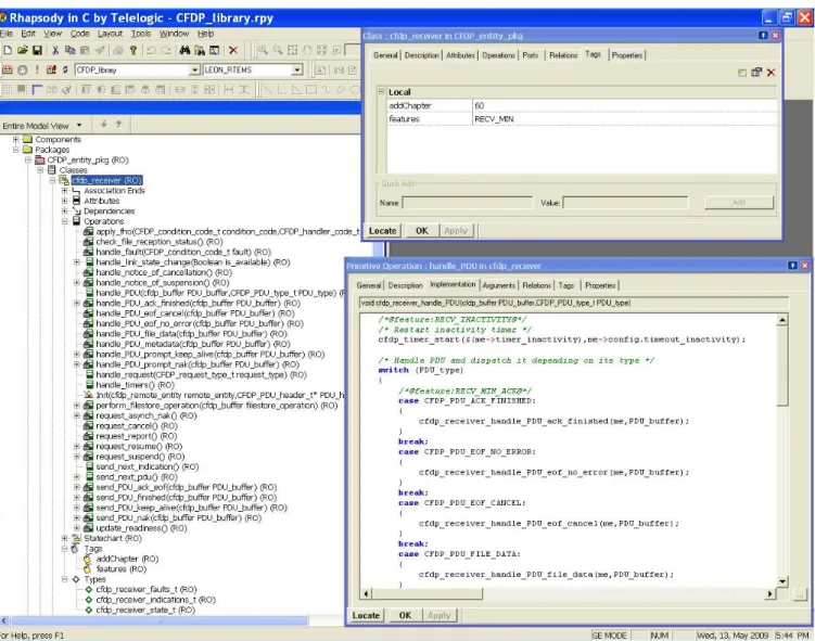
and because it meets all requirements formulated by Spacebel: one can define (complex) constraints between features, it includes a configurator, and the feature se-lection can easily be passed to our makefile. However, our approach does not depend on this tool, other tools may be used too. As mandated by company policy, a commercial UML-based model-driven engineering tool, is used to create design models. We extended the tool so that an engineer can also tag design models with fea-tures, these tags being included in the code generated by the CASE tool. More concretely, we added a tag to the Rhapsody CASE tool using the associated templates. This tag is visible in the top right window of Figure 7. Here again, the approach is general enough to accommo-date any other CASE tool.
The feature modelling step is an addition to the tra-ditional development process. The complete FD of the CFDP product line contains 75 features, several cross-tree constraints, and is up to three levels deep. The only supplemental expertise required from the engineer is knowledge about FDs, which turned out to be very intuitive to use. The main impact of our approach on the design phase is the need to take features into ac-count when defining the architecture. In practice, this means that the architecture will tend to be more mod-ular, so that level features directly map to high-level design artefacts, such as packages. Figure 7 is an excerpt of the CFDP library architecture in which the cfdp receiver class of the CFDP entity pkg package is tagged with the RECV MIN feature (see top right win-dow). As in traditional development, a good design re-duces development time; this effect is amplified since the design has to account for the features that will eventu-ally become tags in the code. Altogether, the overhead caused by our approach was, according to Spacebel en-gineers, rather low: feature modelling and design took an estimated 25% more time than the design phase in similar projects of the company. This overhead is mainly due to the FD drawing task.
5.2 Implementation and testing
The implementation activity itself does not require many changes to existing practice, one of the goals of our ap-proach. The CASE tool is used to generate code skele-tons from the design models, including skeleskele-tons already tagged with features (as described in Section 4). The remaining code is written manually and tagged with features in the process. A few new coding rules were added due to the way the code pruner works, such as the mandatory use of blocks in case statements, for in-stance. Again, the developer needs additional expertise: she has to understand the FD, and to learn the syntax and the semantics of the tagging language. The devel-opers reported that the conceptual overhead caused by feature tags is manageable. During testing and debug-ging, around 20% of the errors were caused by feature tags, and of these only 5% were actual logical errors. The other 95% were all type errors, easily found (resp. corrected) by testing (resp. enforcing) the second design rule from Section 4.3. Feature tagging thus only caused a marginal increase in the number of errors.
In order to determine the overhead caused by the tagging activity and the additional testing, we developed part of the library without feature tags, adding them as part of a second pass over the code. Tagging the code retrospectively took 20% of the time it took to develop the said code. Note that this is a cautious estimate; the developers reported that it is generally easier to tag the code directly than retrospectively.
5.3 Configuration, pruning and compilation
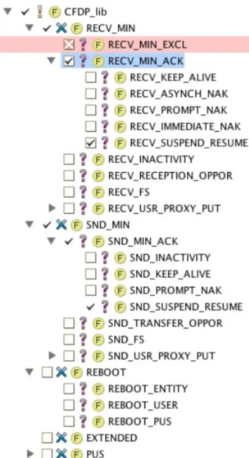
Once the development of the SPL is finished, one can configure and build various products from the SPL. Con-figuration, that is, selecting the features to be included in a product, is done again using pure::variants (reusing the FD elaborated during the design phase). The tool has a graphical interface in which users can select/deselect features in a directory-tree like interface, shown in Fig-ure 8 ; it also prevents the user from making inconsistent choices. The configuration process is thus completely tool-supported. Once a product is obtained, pruning and compilation of the source code are fully automatic. To this end, we developed a pure::variants plug-in that ex-ports a feature selection to command line syntax of the makefile. The deliverables (source code and executable) generated by the makefile constitute the end result of the tool-supported process.
The person doing the configuration needs to have a deep knowledge of the mission requirements as well as a sufficient understanding of the FD, to be able to map mission requirements to features of the library. Note that in the case of the CFDP, configuration is generally not done by the engineer responsible for the design or development of the library, and so special care has been taken to document each individual feature in the FD.
Fig. 7. Excerpt of the CFDP library annotated architecture in Rhapsody
It is during this activity that the initial investment of 20% overhead during development pays off. If this activ-ity were performed manually on untagged code, it would take around 20% of the development time to create each product. The investment thus pays off with the second product. Furthermore, manual code pruning would be error-prone.
6 Evaluation
Here we evaluate the approach and toolchain after the deployment at Spacebel. We first discuss extent to which the initial requirements, formulated in Section 1.2, were satisfied. This is followed by a broader discussion of lessons learnt.
6.1 Initial requirements
(R1) Mass-customisation and no dead code.The first requirement is the outset of the project: be able to
quickly produce a reduced version of a library on de-mand. Mass-customisation is enabled by following an SPL approach, with variability management through FDs. Dead code is avoided by pruning unnecessary code (re-lated to features irrelevant for the specific needs of a mission) before compilation. We have conducted exper-iments to measure the gains in memory and CPU foot-print that can be achieved by customising a library to specific mission requirements: products that correspond to common mission requirements were generated, com-piled, loaded and tested using company’s usual perfor-mance tools. While the full library requires 65 kB of PROM, a version restricted to sending files needs 16.2 kB, four times less. The binaries’ sizes of the numerous (over one billion3) configurations of the CFDP thus vary
between these two values. To put this into perspective, for the LISA Pathfinder (a planned ESA mission which does not use the CFDP protocol), the PROM budget for the entire data handling system, of which the CFDP
Fig. 8. CFDP feature diagram in pure::variants
would be just a small part, is 375 kB. We therefore con-sider this requirement to be met.
(R2) Minimal impact and compliance.The ap-plication domain, satellite on-board systems, comes with a number of stringent development constraints, qual-ity standards and regulations. Those impose develop-ment practices that it would be too costly or even im-possible to change, hence this second requirement. As detailed in the previous section, the transition to our SPLE approach necessitates three changes: (1) specifi-cation and design now include the FD, (2) code has to be developed with tags that trace back to features, and (3) each delivered library goes through a configuration and pruning step. These changes require additional ex-pertise from engineers and developers: FDs and the tag-ging technique. According to the practitioners involved, both are very easy to master and do not affect coding practice in a fundamental way; the development envi-ronment and paradigm are not affected. Altogether the overhead in time ranges from 20% to 25% when com-pared to traditional development. Furthermore, none of these points impacts the technologies used during the development process. Technically, the deliverable is thus indistinguishable from one that would have been devel-oped individually, which meets the compliance require-ment.
(R3) Automation. All of the additional steps are tool-supported, and pruning is fully automated. There
is room for improvement, though. Firstly, FD elabora-tion and configuraelabora-tion will always require user interven-tion and can thus never be completely automated. In previous papers, we proposed methods to further im-prove the configuration process based on the Spacebel case [20,46]. Secondly, although the tagging approach keeps the code very readable (tags minimally alter the code and can be easily recognized), readability could be enhanced by highlighting tagged code fragments (e.g. with colours [26]). Thirdly, the design rules from Sec-tion 4.3 could be checked proactively by the IDE, notify-ing the developer immediately of a type error. Fourthly, integration of the various tools in the toolchain of Fig-ure 6 is currently not very tight in that it occurs only through file exchange. Support for traceability and co-evolution of the involved artefacts is thus rudimentary. A tighter integration of all tools into an IDE would further reduce development costs and risks of errors. While the goal of our code tagging approach was to be independent of a specific IDE, nothing prevents us from developing an IDE that supports the usage of code tags. As long as the IDE is based on code tagging, it will create artefacts that can be edited in any source code editor.
6.2 Lessons learnt and discussion
Return on investment.While it is hard to cite exact numbers, the return on investment of the approach is positive. The overhead required to develop the CFDP as an SPL was an estimated 25%. The advantage gained from this upfront investment is the ability to deliver a customised version of the library very quickly and for a very low marginal cost. We estimate that the investment is redeemed with the first delivered individual product.
Granularity of tagging. Achieving a low granu-larity turned out to be less of a technical problem, and more of a challenge to find intuitive ways to implement tags at low granularity. For instance, we spent consider-able time trying to find an intuitive tag placement for nested if/else if/else structures. The current granu-larity of the tagging approach was based on an analysis of the granularity required for the CFDP implementa-tion. The only experienced limitation at present is the inability to remove individual parameters of a function. However, tagging of parameters and expressions appear to be infrequent and specific to some projects [31,32].
FD Granularity. Initial FDs had a very fine gran-ularity; hundreds of features, up to five levels deep. Ex-periments showed that the advantages gained in terms of memory and CPU footprint would not offset the higher development cost of those fine-grained features and the FD was revised.
Legibility.According to developers, the legibility of the source code is not reduced by the tagging approach (tags are C comments which are rendered in a differ-ent colour in most code editors). However, developers
found it sometimes hard to determine the feature(s) cor-responding to a specific source code fragment, especially in the presence of nested tags. We have developed a pro-totype tool that alleviates this problem with tag-based filter and visualisation techniques [18].
Error proneness and flexibility.The two design rules defined in Section 4.3 are sufficient to guarantee ab-sence of type errors in all possible variants. As mentioned in the previous section, misplaced tags mostly led to type/scope errors which were easily caught and solved. The number of more fundamental errors detected during testing was not increased significantly by the presence of tags. A drawback of the first design rule is that it makes it impossible to have mutually exclusive features declare variables or functions with the same name. This is rather restrictive but does not imply that the approach does not provide support for alternative features. Indeed, such features are not necessarily implemented with similarly-named functions. This rule was not a problem in the case of the CFDP even though it has mutually exclusive features. Evaluating our approach on other cases could lead us to adapt this first design rule.
Threats to validity.While the approach presented in this paper is applicable in a number of situations, it was currently applied to a single project only. We noticed that it is harder to add features to code that was not de-signed and written with features in mind. This confirms the intuition that it is harder to transform a legacy code base into an SPL than to develop an SPL from scratch. It remains to be seen how the approach performs for other projects. We are currently planning to use the approach for a product line of satellite hardware simulation and benchmarking tools. This will also allow us to tackle another threat which is the scalability of the approach. Applying it on the CFDP library (made of 6224 lines of code) was not a problem but we have no evidence that it is the case for larger problems. However, we are rather confident that the approach will scale since feature tags are non-invasive. Another limitation is that the approach has only been applied in a single domain, aerospace, with all its specificities, especially its strict certification rules, and space and memory consumption constraints. Apply-ing the approach in other domains might lead us to re-vise, or even relax, the design rules or propose an inte-grated IDE. Currently, the approach has been applied by two developers at Spacebel. This could be considered as a threat since this population sample is small and both developers have the same background. All those threats could be tackled by applying our approach on different projects in several application domains, so involving dif-ferent developer profiles and project sizes.
7 Related work 7.1 SPL implementation
Gacek et al. [17] discuss different approaches to han-dle variability at the code level, such as inheritance, parametrisation, conditional compilation or overloading. These techniques have several drawbacks. All of them are general-purpose programming techniques, making it im-possible to distinguish constructs that implement vari-ability from those that are part of the ‘normal’ code. As a consequence, features cannot be readily identified in the code and there is thus no straightforward way to actually reduce a codebase to a certain feature set (in order to minimise code size and memory footprint, for instance). Finally, none of those techniques is meant to, much less capable of, representing all kinds of variability found in an SPL, thus leading to an amalgamation of various techniques in the same code base.
Gacek et al. [17] as well as Anastasopoulos and Muthig [1] also investigate aspect-oriented programming (AOP) as an SPL implementation technique. AOP re-quires a paradigm shift and its granularity is generally not sufficient to allow for the insertion of individual statements in methods [26] (a critique applying to most compositional approaches, such as feature-oriented pro-gramming [4]). Even the somewhat fine-grained code in-jection techniques, such as before/after method advice code, or purposely set hooks, have the significant draw-back of not allowing the developer to see the ‘whole pic-ture’. Indeed, the purpose of AOP is to allow the in-jection of crosscutting concerns into the code, which, as shown by Anastasopoulos and Muthig [1], does not sup-port all kinds of variability. For example, if all features of the CFDP library SPL were aspects, then the remaining code would just be a skeleton, making it close to impos-sible to understand, let alone debug, it. Similarly to us, K¨astner et al. [25] evaluated the ability to implement an SPL on a case study, but using AspectJ, i.e., an AOP approach.
One advantage of compositional approaches over an-notative ones is their emphasis on modularity. However, in cases such as the CFDP library, there is no need to modularise the code more than it already is. The size of the applications in this domain as well as the experience of the developers with the modularisation mechanisms provided by C or C + + are sufficient; in fact, any fur-ther modularisation would most likely entail overhead rather than benefits.
Patzke and Muthig [35] propose frame technology, an annotative approach which aim is to explicitly rep-resent variation points in the code. The problem there is that the implementation mixes the code representing variable behaviour with information about how this be-haviour can vary, hence violating the principle of separa-tion of concerns [44]. Indeed, a variasepara-tion point exists on a much higher level than the code, since not only the code
has variability, but so have the design and the require-ments. We therefore explicitly separate variability (the FD) from implementation according to the principles of orthogonal variability modelling [38].
In response to the limitations of compositional ap-proaches, especially when reengineering a legacy code base as a product line, K¨astner et al. [26] propose CIDE. CIDE lets the developer use colours to label code frag-ments that pertain to certain features. Their approach is similar to ours in that code annotations are in fact anno-tations of the abstract syntax tree. The main limianno-tations of annotative approaches tackled by CIDE, such as un-readable code or error-prone development, are solved by our code tagging approach as well. Their approach has the advantage of being integrated with an IDE, allowing for instance, to filter the displayed code to show only one feature [24]. Similarly to our approach, CIDE sup-ports alternative features [27]. Their approach, however, also has a number of limitations. CIDE is tightly inte-grated with the Eclipse IDE, storing annotations in sep-arate files. Our code tags, on the contrary, are part of the source code itself, meaning that they can be copy/pasted, and that the resulting source code is portable (i.e. can be viewed and edited with any editor). Obviously, one could modify CIDE annotation files with any text edi-tor. However, editing and maintaining these files would be cumbersome and error-prone, since they have to be kept in sync with every edit to the source code.Finally, the choice of colour as the primary means to indicate features (as opposed to colour just being a way to visu-alise features), leads to limitations when the number of features is high (close to 80 in our case), when annota-tions are nested, or when fragments pertain to several features.
7.2 Type correctness
In [45], Thaker et al. define the notion of safe compo-sition as “the guarantee that programs composed from feature modules are type safe”. It means that no ref-erence to undefined classes, methods, variables,. . . can exist in the pruned source code. In [24], K¨astner and Apel show how the Featherweight Java calculus can be extended with feature annotations in order to guarantee that all possible configurations of a well-typed SPL are well-typed as well. The main drawback of the proposal is that it only covers a subset of a very specific pro-gramming language, and is thus not directly applicable in practice. With code tagging, we can easily guarantee safe composition by following two testable design rules explained in Section 4.3.
7.3 Pruning
A related approach with a focus on models for SPLE (rather than code) is proposed in [15]. This approach
involves annotating fragments of a UML model (such as a class diagram, for instance) with so-called ‘presence conditions’. A presence condition is a Boolean expression over the features of an FD, which for a given configura-tion of the FD is true or false. To obtain the model corre-sponding to a specific configuration, the model fragments whose expressions evaluate to false are pruned. This ap-proach is similar to code tagging, in that a code tag is actually a presence condition consisting of a disjunction of features. Incidentally, the authors mention that the higher expressivity of arbitrary Boolean expression is of-ten not needed in practice, and conof-tend that “the ma-jority of elements is annotated with single features”[15]. The advantage of code tags as disjunctions of features is that code pruning becomes monotonic, which is an im-portant requirement for safe composition in our case, as explained in Section 4.3. A similar tool is FeatureMap-per [19], which also allows to link features of FDs to design models (defined in Ecore-based languages) and so enable pruning and filtering of models based on fea-ture selections. In our case, design models and FDs had to be linked using tags in the Rhapsody CASE tool since Spacebel cannot use any other tool for certification rea-sons, as mentioned in the introduction.
7.4 Tagging
Storey et al. [42] investigate code tagging from the per-spective of asynchronous and collaborative program de-velopment. Their approach is supported by the open-source tool TagSEA, and its purpose is to enhance navi-gation and knowledge distribution in the code files them-selves. This approach is complementary to ours and partly confirms our choice of tagging as an appropriate means to annotate code. Integrating TagSEA within our toolchain would be a nice way to improve visualisation and naviga-tion. A first prototype has already been developed [18]. 8 Conclusion
To implement variation points at the code level, prod-uct line methods classically advocate usage of inheri-tance, components, frameworks, aspects or generative techniques. The problem of these techniques is that they often require unaffordable paradigm shifts from the de-velopers if the software was not thought at the outset of a product line. Furthermore, these techniques can be conflicting with a company’s coding practices or exter-nal regulations. As a consequence, we developed an ap-proach to implementing software product lines as part of a partnership between industry and university. The proposal combines previous ideas in a unique way and pursues three principal goals: (1) be able to remove all the code that belongs to non selected features, (2) have a minimal impact on current development practices, and (3) automate the solution as much as possible.
The result is an approach that spans the whole devel-opment process and is supported by a toolchain. The ap-proach uses feature diagrams to capture variability and its kernel consists of a novel technique for tagging por-tions of code with features. After configuring a product, a feature parser is run over the codebase, which creates a new codebase without the fragments that pertain to non selected features. Code tagging has several advantages over existing software product lines implementation ap-proaches. Mainly, it uses a special code style and it is a conservative extension of the programming language that entails very little overhead for the programmer.
The proposed approach has been used successfully for the development of a flight grade satellite file transfer library product line. The feature parser is implemented for C, but the principles behind code tagging are general enough for it to transpose to most imperative program-ming languages. The same conclusion applies to design models. We thus believe that the approach can be easily applied to a variety of projects.
In the future, we intend to extend this work in several ways. One is to apply the process to other projects in or-der to test its adaptability and improve it with new feed-back. Another is to strengthen communication among the different components and extend our approach with additional components, e.g., to enhance visualisation and navigation.
Acknowledgements. This work was partially funded by the Walloon Region under the European Regional Development Fund (ERDF), the Interuniversity Attraction Poles Programme, Belgian State, Belgian Science Policy, the BNB and the FNRS.
References
1. M. Anastasopoulos and D. Muthig. An evaluation of aspect-oriented programming as a product line imple-mentation technology. In Proceedings of ICSR’04, pages 141–156. Springer, 2004.
2. M. Antkiewicz and K. Czarnecki. Featureplugin: feature modeling plug-in for eclipse. In Proceedings of Eclipse’04 (OOPSLA workshop), pages 67–72. ACM, 2004. 3. S. Apel, T. Leich, and G. Saake. Aspectual feature
modules. IEEE Transactions on Software Engineering, 34(2):162–180, 2008.
4. D. S. Batory. Feature-oriented programming and the ahead tool suite. In Proceedigs of ICSE’04, pages 702– 703. IEEE, 2004.
5. D. S. Batory. Feature models, grammars, and proposi-tional formulas. In Proceedings of SPLC’05, pages 7–20. Springer, 2005.
6. D. S. Batory, J. N. Sarvela, and A. Rauschmayer. Scaling step-wise refinement. In Proceedings of ICSE’03, pages 187–197. IEEE, 2003.
7. D. Benavides, S. Segura, and A. R. Cort´es. Automated analysis of feature models 20 years later: A literature review. Inf. Syst., 35(6):615–636, 2010.
8. D. Beuche. Modeling and building software product lines with pure: :variants. In Proceedings SPLC’08, page 358. IEEE, 2008.
9. Q. Boucher, A. Classen, P. Heymans, A. Bourdoux, and L. Demonceau. Tag and prune: a pragmatic approach to software product line implementation. In Proceedings of ASE’10, pages 333–336. ACM, 2010.
10. CCSDS. CCSDS File Delivery Protocol (CFDP): Blue Book, Issue 4 and Green Book, Issue 3. Number CCSDS 727.0-B-4, CCSDS 720.1-G-3. NASA, 2007.
11. A. Classen, P. Heymans, and P.-Y. Schobbens. What’s in a feature: A requirements engineering perspective. In Proceedings of FASE’08, volume 4961 of LNCS, pages 16–30. Springer, 2008.
12. P. C. Clements and L. Northrop. Software Product Lines: Practices and Patterns. Addison-Wesley, 2001.
13. K. Czarnecki and U. W. Eisenecker. Generative Program-ming. Methods, Tools and Applications. Addison-Wesley, 2000.
14. K. Czarnecki, S. Helsen, and U. W. Eisenecker. Staged configuration through specialization and multilevel con-figuration of feature models. Software Process: Improve-ment and Practice, 10(2):143–169, 2005.
15. K. Czarnecki and K. Pietroszek. Verifying feature- based model templates against well-formedness ocl constraints. In Proceedings of GPCE’06, pages 211–220. ACM, 2006. 16. P. Ebraert, A. Classen, P. Heymans, and T. D’Hondt. Feature diagrams for change-oriented programming. In Proceedings of ICFI/FIW’09, pages 107–122. IOS Press, 2009.
17. C. Gacek and M. Anastasopoules. Implementing prod-uct line variabilities. SIGSOFT Softw. Eng. Notes, 26(3):109–117, 2001.
18. C. Gauthier, A. Classen, Q. Boucher, P. Heymans, M.-A. Storey, and M. Mendonca. XToF: A tool for tag-based product line implementation. In Proceedings of VaMoS’10, pages 163–166. University of Duisburg-Essen, 2010.
19. F. Heidenreich, J. Kopcsek, and C. Wende. Featuremap-per: mapping features to models. In Proceedings of ICSE’08, pages 943–944. ACM, 2008.
20. A. Hubaux, A. Classen, and P. Heymans. Formal mod-elling of feature configuration workflows. In Proceedings of SPLC’09, pages 221–230. ACM, 2009.
21. S. Jarzabek, P. Bassett, H. Zhang, and W. Zhang. Xvcl: Xml-based variant configuration language. In Proceed-ings of ICSE’03, pages 810–811. IEEE, 2003.
22. K. Kang, S. Cohen, J. Hess, W. Nowak, and S. Peter-son. Feature-oriented domain analysis (FODA) feasibil-ity study. Technical Report CMU/SEI- 90-TR-21, SEI, Carnegie Mellon University, Nov. 1990.
23. C. K¨astner and S. Apel. Integrating compositional and annotative approaches for product line engineering. In Proceedings of GPCE’08, pages 35–40. University of Pas-sau, 2008.
24. C. K¨astner and S. Apel. Type-checking software product lines - a formal approach. In Proceedings of ASE’08, pages 258–267. IEEE, 2008.
25. C. K¨astner, S. Apel, and D. S. Batory. A case study implementing features using aspectj. In Proceedings of SPLC’07, pages 223–232. IEEE, 2007.
26. C. K¨astner, S. Apel, and M. Kuhlemann. Granularity in software product lines. In Proceedings of ICSE’08, pages 311–320. ACM, 2008.
27. C. K¨astner, S. Apel, T. Th¨um, and G. Saake. Type checking annotation-based product lines. ACM Transactions on Software Engineering and Methodology (TOSEM), 2012. To appear.
28. C. K¨astner, S. Apel, S. Trujillo, M. Kuhlemann, and D. S. Batory. Guaranteeing syntactic correctness for all product line variants: A language-independent ap-proach. In Proceedings of TOOLS Europe’09, pages 175– 194. Springer, 2009.
29. C. K¨astner, T. Th¨um, G. Saake, J. Feigenspan, T. Leich, F. Wielgorz, and S. Apel. Featureide: A tool framework for feature-oriented software development. In Proceedings of ICSE’09, pages 611–614. IEEE, 2009.
30. C. W. Krueger. Biglever software gears and the 3-tiered spl methodology. In Proceedings of OOPSLA’07, pages 844–845. ACM, 2007.
31. J. Liebig, S. Apel, C. Lengauer, C. K¨astner, and M. Schulze. An analysis of the variability in forty preprocessor-based software product lines. In Proceed-ings of ICSE’10, pages 105–114. ACM, 2010.
32. J. Liebig, C. K¨astner, and S. Apel. Analyzing the disci-pline of preprocessor annotations in 30 million lines of c code. In Proceedings of AOSD’11, pages 191–202. ACM, 2011.
33. M. Mendonca, M. Branco, and D. Cowan. S.p.l.o.t.: Soft-ware product lines online tools. In Proceeding of OOP-SLA’09, pages 761–762. ACM, 2009.
34. MISRA. MISRA-C: Guidelines for the use of the C lan-guage in critical systems. Motor Industry Research As-sociation, UK, 2008.
35. T. Patzke and D. Muthig. Product line implementation with frame technology: A case study. Technical Report 018.03/E, Fraunhofer IESE, 2003.
36. R. Pawlak. Spoon: Compile-time annotation process-ing for middleware. IEEE Distributed Systems Online, 7(11):1, 2006.
37. K. Pohl, G. B¨ockle, and F. J. van der Linden. Software Product Line Engineering: Foundations, Principles and Techniques. Springer, Secaucus, NJ, USA, 2005. 38. K. Pohl and A. Metzger. Variability management in
software product line engineering. In Proceedings of ICSE’06, pages 1049–1050. ACM, 2006.
39. P.-Y. Schobbens, P. Heymans, and J.-C. Trigaux. Fea-ture diagrams: A survey and a formal semantics. In Pro-ceedings of RE’06, pages 136–145. IEEE, 2006.
40. Y. Smaragdakis and D. S. Batory. Mixin layers: an object-oriented implementation technique for refine-ments and collaboration-based designs. ACM Trans. Softw. Eng. Methodol., 11(2):215–255, 2002.
41. H. Spencer and G. Collyer. #ifdef considered harmful, or portability experience with c news. In Proceedings of USENIX’92, pages 185–198. USENIX Association, 1992. 42. M.-A. Storey, L.-T. Cheng, I. Bull, and P. Rigby. Shared waypoints and social tagging to support collaboration in software development. In Proceedings of CSCW’06, pages 195–198. ACM, 2006.
43. C. A. Szyperski. Component software - beyond object-oriented programming. Addison-Wesley-Longman, 1998. 44. P. Tarr, H. Ossher, W. Harrison, and S. M. J. Sutton. N degrees of separation: multi-dimensional separation of concerns. In Proceedings of ICSE’99, pages 107–119. ACM, 1999.
45. S. Thaker, D. S. Batory, D. Kitchin, and W. Cook. Safe composition of product lines. In Proceedings of GPCE’07, pages 95–104. ACM, 2007.
46. T. T. Tun, Q. Boucher, A. Classen, A. Hubaux, and P. Heymans. Relating requirements and feature con-figurations: A systematic approach. In Proceedings of SPLC’09, pages 201–210. ACM, 2009.
![Fig. 1. A CFDP scenario (adapted from [10])](https://thumb-eu.123doks.com/thumbv2/123doknet/14566161.726852/3.892.488.787.137.307/fig-a-cfdp-scenario-adapted-from.webp)