Design of an STM and EPL Control System and Linear Actuator Preload Diaphragm
by
Earl Taylor Roan
SUBMITTED TO THE DEPARTMENT OF MECHANICAL ENGINEERING IN PARTIAL FULFILLMENT OF THE REQUIREMENTS FOR THE DEGREE OF
BACHELOR OF SCIENCE AT THE
MASSACHUSETTS INSTITUTE OF TECHNOLOGY JUNE 2007
©2007 Earl Taylor Roan. All rights reserved. The author hereby grants to MIT permission to reproduce
and to distribute publicly paper and electronic copies of this thesis document in whole or in part
in any medium now known or hereafter created.
Signature of Author:_______________________________________________________ Department of Mechanical Engineering
Date
Certified by:_____________________________________________________________ Thesis Supervisor’s Name (full name)
Thesis Supervisor’s Title (full title) Thesis Supervisor Accepted by:_____________________________________________________________
John H. Lienhard V Professor of Mechanical Engineering
Design of an STM and EPL Control System and Linear Actuator Preload Diaphragm
by
Earl Taylor Roan
Submitted to the Department of Mechanical Engineering on May 11, 2007 in partial fulfillment of the
requirements for the Degree of Bachelor of Science in Engineering as recommended by the Department of Mechanical Engineering
ABSTRACT
Increasing demand for nano-scale machining processes in the semiconductor industry necessitates new mechanisms for nano-machining. A system capable of nano-scale machining of conductive material via Electronic Pen Lithography (EPL) may fit this niche. The purpose of this research is to develop a system capable of EPL based on a HexFlex six axis nano-manipulator.
The system will also be capable of Scanning Tunneling Microscopy (STM), which is will locate the surface with the precision necessary for EPL and also allow the user to confirm the machined features immediately after machining. The import of this work is the development of a low-cost and compact system for nano-machining and nano-scale imaging. The impact of this work may improve the process for manufacturing
semiconductors including circuitry, MEMS, and NEMS. The continued development of full six axis machining techniques may allow for the construction of features hitherto impossible to fabricate.
This segment of the project focuses on the integration of the HexFlex, a micron stepper motor, precision mounts, a preload diaphragm, and an advanced control system capable of automated EPL and STM verification. Steady electron tunneling is first demonstrated, followed by STM imaging functionality. However, high-speed, high-accuracy EPL machining techniques are reserved for future work.
Thesis Supervisor: Martin L. Culpepper
ACKNOWLEDGEMENTS
Many thanks to Dariusz Golda, Robert Panas, and Professor Martin L. Culpepper for their help in this work. Dariusz developed the HexFlex device and drivers along with the sample mount and kinematic coupling. He also helped troubleshoot the electronics and control systems and offered invaluable advice throughout the entire process. Robert aided with development of the functional requirements of the system, and developed wonderful dynamic models of the gap dynamics. Professor Culpepper oversaw the entire process, allocated resources to the research and provided helpful feedback all along the way.
And extra thanks to my beautiful wife, Kana, who although pregnant, has put up with me spending many late nights on this research and other academic work.
Table of Contents
Abstract ... 3 Acknowledgements... 5 Table of Contents... 7 List of Figures ... 9 List of Tables ... 11 Chapter 1: Introduction ... 13 1.1 Project History ... 13 1.2 Components ... 15 1.3 Contributions... 17 Chapter 2: Background ... 192.1 Electronic Pen Lithography ... 19
2.2 The HexFlex... 21
Chapter 3: Design ... 25
3.1 System Overview ... 26
3.2 The Mechanical Assembly... 26
3.3 The Linear Stage ... 28
3.4 The Linear Bearing ... 30
3.5 The Stepper Motor ... 32
3.6 The Probe Tip Mount... 33
3.7 The Kinematic Coupling... 35
3.8 System Electronics... 37
3.9 The Control System ... 39
3.10 System Modeling ... 41
Chapter 4: Characterization ... 45
4.1 Linear Stage Characterization... 45
4.2 System Background Noise... 46
4.3 Establihing Tunneling Current... 47
Chapter 5: Conclusions ... 52 References... 53
List of Figures
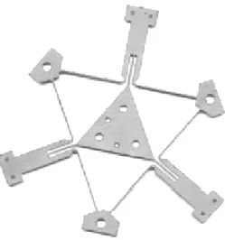
Figure 1.0: A HexFlex compliant mechanism ... 14
Figure 1.1: The original EPL device... 15
Figure 1.2: Probe tip actuation error propagation ... 17
Figure 2.1a: EPL machined sample. ... 20
Figure 2.1b: STM imaging... 21
Figure 2.2a: The meso-scale HexFlex prototype ... 22
Figure 2.2b: HexFLex actuation components... 23
Figure 2.2c: HexFlex motions... 24
Figure 3.2: The current EPL system design... 27
Figure 3.3: The linear stage ... 29
Figure 3.4a: The linear bearing... 31
Figure 3.4b: A diaphragm flexure FEA ... 32
Figure 3.5: The stepper motor... 33
Figure 3.6: The probe tip mount ... 35
Figure 3.7: The kinematic coupling ... 36
Figure 3.8a: The HexFlex driver... 37
Figure 3.8b: The 40105 chopper drive... 38
Figure 3.8c: The Keithley 6485 picoammeter ... 38
Figure 3.9a: The control system schematic... 39
Figure 3.9b: The control system GUI ... 40
Figure 3.10a: Failure mode 1: Excessive approach velocity ... 42
Figure 3.10b: Failure mode 2: Inadequate gap ... 43
Figure 3.10c: Failure mode 3: Excessive EPL pulse voltage... 44
Figure 4.1: Histogram of linear stage step size... 46
Figure 4.2: Background system electronic noise ... 47
Figure 4.3a: Initial tunneling current establishment ... 48
Figure 4.3b: Improved tunneling feedback control... 49
Figure 4.4b: Scan time dependence ... 51 Figure 4.4c: X-Y and X-Z plots... 51
List of Tables
Figure 3.1: System FR-DP... 26
Figure 3.2: Mechanical system FR-DP ... 28
Figure 3.3: Linear stage FR-DP ... 29
Figure 3.4: Linear bearing FR-DP ... 30
Figure 3.5: Stepper motor FR-DP... 32
Figure 3.6: Probe tip mount FR-DP... 34
CHAPTER 1
Introduction
Electronic Pen Lithography (EPL) is a new means of producing nano-scale features in conductive substrates. There is currently no system available that is designed specifically for EPL. EPL has been achieved through modification of existing Scanning Tunneling Microscopes (STMs). These STMs may cost thousands of dollars. In
addition, STMs may also have unfavorably low natural frequencies which can impede high-speed sensing and fabrication [1]. These problems warrant the development of an inexpensive and effective system designed specially for EPL machining.
The aforementioned problems may be solved through implementation of an electromechanically activated HexFlex style six-axis compliant mechanism. The HexFlex is a scalable precision compliant mechanism that is capable of six-axis,
nanometer-scale motion. These devices are expected to be well-suited to use in scanning tunneling microscopy (STM) and electro-pen lithography (EPL) machining due to:
• high repeatability (less than a nanometer) • high natural resonance frequencies • low cost (less than 100 USD)
• small size (meso-scale and micro-scale versions exist)
Figure 1.0: HexFlex precision compliant mechanisms can be made very inexpensively thanks to simple 2D geometry. [3].
Due to design simplicity, the HexFlex can easily be manufactured with ubiquitous 2D machining techniques like water-jetting. The HexFlex’s characteristics and
functionality are expounded in Section 2.2.
1.1 Project History
This project was initialized in the summer of 2005 to demonstrate the functional benefits of HexFlex devices and the possibility of more inexpensive and repeatable means of EPL nano-machining techniques. Dariusz Golda fabricated a simple prototype system which incorporated the HexFlex device, a probe-tip, a micrometer, and a
Figure 1.1: Dariusz Golda’s original HexFlex based EPL device. [Photo courtesy Dariusz Golda, 2006]
However, the system was unable to consistently achieve either STM or EPL functionality without feedback loop control and sufficiently precise probe-tip approach algorithms. In order to improve the first prototype, and more effectively demonstrate the potential for EPL machining, the tabletop HexFlex based precision STM/EPL system has been reconstructed with several new subsystems that are essential to consistent and automated functionality of the device. The kinematic coupling, HexFlex, drivers, sample mount, and probe-tips were inherited from the original prototype. A phenolic probe-tip mount, diaphragm flexure, automated feedback control system, and a linear actuator have been added to this second iteration. A brief overview of these components follows.
Kinematic
Coupling
Probe
Cable
HexFlex
Circuitry
Micrometer
1.2 Components
A special tip approach system is necessary to position the probe-tip within
scanning range of the HexFlex. Although the HexFlex is capable of moving the working sample with nanometer resolution, only three microns maximum travel can be attained. The tip may only be placed by hand initially at a distance of about five millimeters. Therefore, the probe-tip must be actuated separately over a range of at least five
millimeters with a resolution of less than the three micron range of the sample stage. In order to approach the sample, the probe-tip is interfaced with a stepper motor with a step size of less than three microns. This required the integration of the probe-tip and the linear actuator via a special interface. This interface will be referred to as the “linear actuator mount.”
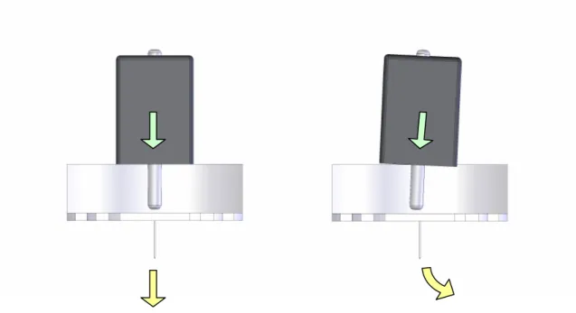
Another subsystem is needed to attenuate propagation of error and parasitic motions in actuation of the probe tip by the stepper motor. Unfortunately, noticeable parasitic motions are produced on the micro- or nano-scale with any actuation on the macro- or meso-scale due to inevitable misalignment and asymmetries in component geometry. The five millimeter overall motion of the linear actuator will surely result in some lateral motion and rotation of the tip. If the stepper motor pushes on the flexure that holds the tip at a slight angle or slightly to the left or right of the center of stiffness, the tip will not move in a purely vertical path, but rather rotate and translate to either side. An example of error propagation is shown in Figure 1.2. An angled tip or swinging actuation may result in decreased accuracy of system characterization. Attenuation of unwanted motions is achieved with a precision flexure diaphragm that attenuates all non-axial motion. This reduces the amount of error due to misalignment of the stepper motor
and component imperfections. The diaphragm also functions to improve the step size repeatability of the actuator by eliminating backlash with a preload. This parasitic motion attenuator will be referred to as the “diaphragm flexure.” This flexure attaches to the probe-tip via the “probe-tip mount.”
Figure 1.2: Ideal tip actuation is shown on the left. Even a small misalignment of the stepper motor actuation can cause the tip to swing or translate instead of approaching
vertically, as shown on the right. These unwanted motions may be reduced with a diaphragm flexure.
A closed loop feedback control system capable controlling the HexFlex motion is essential for successful STM imaging and EPL machining. STM’s operate on current changes on the order of tens of nanoamps. Background noise in the current signal is about 20 times that amount, depending on the hardware. The control must be capable of filtering the signal because of this large signal to noise ratio. At the same time, the system must retain a rise time much less than the natural frequency of the HexFlex subsystem to allow for compensation of mechanical vibrations. The control system
designed in MATLAB’s Simulink and executed in Control Desk is capable of this control.
1.3 Contributions
The integration of the STM/EPL system includes a high-precision, single-axis motion bearing (a combination of properly spaced diaphragm flexures), a dielectric probe-tip mount, an appropriate stepper motor, and integration of each of these elements with the HexFlex. This segment of the project includes the design, manufacture, and assembly of the single-axis motion bearing and the dielectric probe-tip mount, and interfacing these parts with the stepper motor and assembly as a whole. In addition, development of the control system capable of monitoring the STM and EPL processes and driving each actuator for effective STM and EPL is required.
Brief explanations of STM, EPL, and the HexFlex are located in the background section. The design section contains the functional requirements of the system and design processes. Experimental data is found in the characterization section. Lastly, conclusions drawn from the research are presented.
CHAPTER 2
Background
Understanding the functional requirements of the STM/EPL system as a whole demands explanation of the Scanning Tunneling Microscopy (STM) and Electronic Pen Lithography (EPL) processes. Each technique is briefly discussed below. Furthermore, the HexFlex deserves introduction as several design requirements stem from its range and other characteristics.
2.1 Electronic Pen Lithography
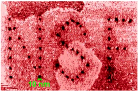
Electronic Pen Lithography (EPL) is a means of nano-fabricating features that are as small as 10 nm in diameter. EPL machining has the potential to allow for increasingly small, rapid, and inexpensive fabrication of circuit boards, sensors, and other devices. The EPL process removes material by discharging electricity between a sharp charged probe-tip and the material to be machined at a distance of about 50 nm.
Upon locating the conductive surface, the tip is retracted to the appropriate distance and the potential difference of the tip and substrate is increased until the voltage discharges. This arching electric discharge dissociates (effectively removes) almost perfectly round 10 nm diameter hemispheres of material at the surface closest to the probe-tip. The EPL machining technique was developed at the University of Arkansas by Professor Ajay Malshe, a research partner with MIT’s Precision Compliant System Lab (PCSL). The University of Arkansas has demonstrated the ability to create the features
shown in Figure 2.1a [4]. The acronym for the National Science Foundation, “NSF,” is etched into gold plate.
Figure 2.1a: EPL machining techniques have been demonstrated by researchers at the University of Arkansas who etched these letters into gold plate. (Image used by
permission and located at LifeScience.com [4], scale added)
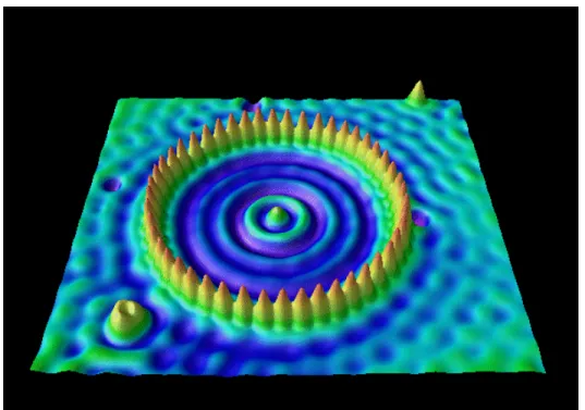
The surface of the conductive working material (such as gold plate) must first be located with nanometer resolution in order for the 50 nm gap required for EPL to be achieved. Scanning Tunneling Microscopy techniques have been the most convenient way to locate the surface because the same apparatus may be used for STM and EPL. STM is based on the measurement of electron tunneling current (electron transfer between atoms close enough that their wave functions overlap) into the material from a charged probe-tip very close to the surface. The tip is charged and approaches the
surface until a tunneling current is measurable. This usually occurs when the tip is within about two nanometers of the surface. Images such as the one shown in Figure 2.1b [5] are produced by scanning the surface parallel to the plane with tunneling current
feedback. This project is the design and construction of a system capable of both STM and EPL.
Figure 2.1b: An image captured via STM. Each mound represents the electron cloud of a single atom. (Image used by permission and located at almaden.ibm.com [5])
Any mechanism capable of nano-scale resolution, including STM and EPL devices, is sensitive to thermal drift and ambient vibrations. Natural frequencies that correspond to the ambient vibration frequencies amplify the externally induced
vibrational noise. The implemented design includes component geometries, materials, environmental control systems, electronic feedback mechanisms that attenuate and compensate for the effects of ambient vibrations and fluctuations in temperature.
2.2 The HexFlex
The original HexFlex [6] was created by Gordon Anderson and Professor Martin Culpepper of MIT’s Precision Compliant Systems Lab (PCSL). The HexFlex is capable
of sub-nanometer resolution motion in six axes. The HexFlex has over 300 times the resistance to thermal drift of other more expensive nano-manipulators and can be
manufactured less than a tenth the price at about $3,000. The high precision performance of the HexFlex style actuator is ideal for STM and EPL applications.
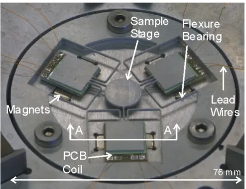
Figure 2.2a shows a bench-level prototype meso-scale (76.2 mm diameter) electromagnetically driven HexFlex developed by Dariusz Golda, MIT PhD candidate. This device is based on the original HexFlex, but is designed specifically for an
STM/EPL device [2]. A micro-scale prototype version of this device has been created for future use in smaller versions of this application. Successful implementation of these devices may decrease the size of a high-speed STM and EPL system to the size of a water bottle or soda can.
Figure 2.2a: The prototype meso-scale six-axis precision actuator. (Image extracted from “A Scalable Six-Axis Electromagnetically-Driven Nanopositioner For
The HexFlex device relies on the compliance of the device members as bearings to facilitate motion. Compliant systems are used because, when designed correctly, they may have angstrom-level resolution when actuated below 30% of the yield stress [7]. As a compliant mechanism, the HexFlex has the resolution necessary for effective STM and EPL of a conductive substrate.
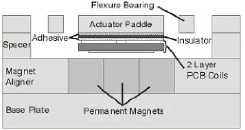
Different from most STM devices, this project’s design positions the substrate with the HexFlex rather than the probe-tip. The material to be measured or machined is attached to the round sample stage in the center of the HexFlex. The HexFlex features three actuator paddles branching from the sample stage. A pair printed circuit board coils are joined to each of the actuator paddles. These paddles are mounted directly above corresponding sets of permanent magnets. Two-axis actuation of each paddle may be obtained by controlling current through the PCB coils. A cross-sectional schematic of the device is shown in Figure 2.2b [2].
Figure 2.2b: Cross-sectional view of the actuator components of the HexFlex paddles including PCB coils and permanent magnets. (Image extracted from “A Scalable
Six-Axis Electromagnetically-Driven Nanopositioner For Nanomanufacturing” [2])
Six-axis motion of the sample stage is obtained by combined actuation of the three actuator paddles. For example, a positive z-direction actuation of one paddle
combined with a smaller and negative z-direction actuation of the other paddles results in a pure rotation of the sample stage as seen in Figure 2.2c [2]. Calibration of the device eliminates parasitic nonlinear effects in the motion of the center stage to sub-nanometer precision [2]. The conductive substrate on the sample stage may thus be moved relative to a fixed STM probe-tip.
Figure 2.2c: Various motions of the circular sample stage are obtained by actuating the square paddles of the HexFlex. (Image extracted from “A Scalable Six-Axis
Electromagnetically-Driven Nanopositioner For Nanomanufacturing” [2])
STM and EPL are possible with the six-axis angstrom-level resolution motions relative to the probe-tip provided by the HexFlex. For STM, the sample stage and substrate surface are passed parallel to the probe-tip with a nearly constant 10 nm gap maintained by a tunneling current feedback loop to scan the surface. The sample stage may also be removed to a distance of 50 nm from the probe-tip facilitate EPL machining. The HexFlex mechanism used is scalable and capable of high-speed scanning and
CHAPTER 3
Design
Design for each system, subsystem, and component is done in a three step process.
1) Assessing the dependence of functional requirements and design parameters 2) Proposing and analyzing a possible solution via calculation or modeling in
engineering software.
3) Fabricating the necessary parts and confirming anticipated performance.
The Functional Requirement vs. Design Parameter (FR-DP) correlation diagram shows whether the functional requirements of a component may be decoupled and
designed axiomatically. In the FR-DP diagrams in this paper, the functional requirements are listed in the uppermost row, and the design parameters are listed in the leftmost column. “X”s mark the dependence of a functional requirement on a given design parameter. Components capable of axiomatic design contain no dependencies above the matrix diagonal. Straightforward designs have only a diagonal of X’s.
Analysis via calculation includes simple comparisons of desired mechanical properties among alternative materials, diagrams, stiffness calculations, or differential models of temporal trajectories. Analysis via modeling has been done using FEA programs such as those bundled with SolidWorks.
Most parts were fabricated using water-jet cutting techniques while others were milled or turned on a lathe depending on the properties and geometry of the part. Other components such as the linear actuator, its driver, and the picoammeter were purchased.
3.1 System Overview
The system must be capable of locating the surface and scanning the surface. The tip actuator is primarily for closing the millimeter-scale distance between the sample and the probe tip. However, the linear actuator’s resolution is over a micron and cannot control the gap within nanometers, as required for STM and EPL. The HexFlex obtains and controls the remaining gap with subnanometer-scale resolution to achieve and maintain tunneling current. The HexFlex is also entirely responsible for scanning motions. The FR-DP diagram for this design is shown in Table 3.1.
Obtain Gap Scan Sample
Tip Actuator X
HexFlex X X
Table 3.1: FR-DP diagram of the system.
The remaining main components of the system are the electronic and computational devices. Each of the electronics components, most of which were purchased, will be introduced in section 3.8. The control system is responsible for control of the sample position, the approach algorithm, and data acquisition. A more detailed explanation the control system architecture is contained in section 3.9.
3.2 The Mechanical Assembly
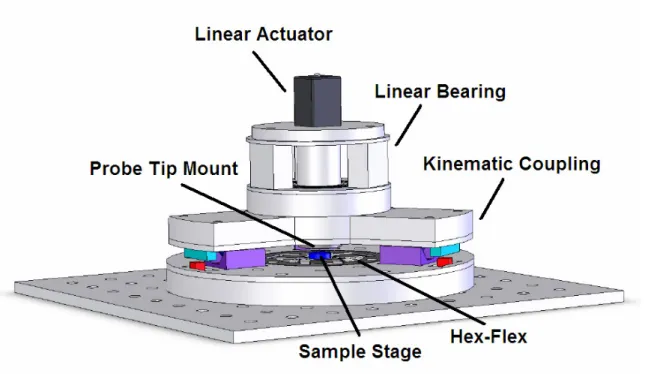
The current design for the entire assembly is shown in Figure 3.2. The linear actuator assembly that controls the motion of the probe-tip will be mounted atop a kinematic coupling. The HexFlex and sample holder will be mounted to the bottom half of the kinematic coupling.
Figure 3.2: The current design of the EPL apparatus.
The total vertical travel of the HexFlex actuated sample stage is only about three microns. The probe-tip is impossible to initially position within this distance of the sample stage repeatedly. In order to bring the probe-tip to within the range of the HexFlex, the tip must be displaced vertically after mounting. A structure must be designed and manufactured to mount the linear actuator to the assembly. Functionally, this structure must also both preload the linear actuator with 1 - 10 N of force and permit
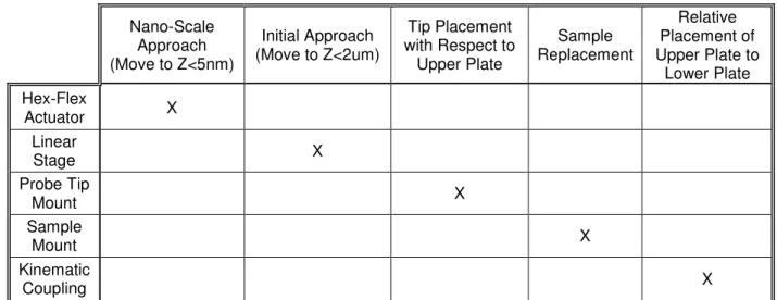
other motions. The probe-tip motion should also be repeatable to within a few nanometers. Nano-Scale Approach (Move to Z<5nm) Initial Approach (Move to Z<2um) Tip Placement with Respect to Upper Plate Sample Replacement Relative Placement of Upper Plate to Lower Plate Hex-Flex Actuator X Linear Stage X Probe Tip Mount X Sample Mount X Kinematic Coupling X
Table 3.2: FR-DP diagram of the mechanical assembly.
The mechanical assembly has five basic functional requirements – (1) The tip must be capable of a millimeter-scale initial motion toward the sample, which is
necessary for an initial rough tip approach. This rough approach travel is achieved with the linear stage sub assembly. (2) The sample must then approach the tip with a finer nanometer-scale resolution to avoid crashing the sample into the tip and to control the tunneling current. The HexFlex fulfills this requirement. (3) The tip and (4) sample must be replaceable. These functional requirements are achieved by the “Probe Tip Mount” and the “Sample Mount” respectively. (5) The top and bottom subassemblies must be repeatedly repositionable when the apparatus is opened to change either the probe tip or the sample. This requirement is fulfilled by the implementation of a kinematic coupling. The FR-DP matrix is shown in Table 3.2. The correlation between functional
as a whole, the system can be designed axiomatically because each functional requirement is met by a single design parameter.
3.3 The Linear Stage
The linear stage must be able to hold the tip and move the tip vertically toward the sample over a range of up to five millimeters. The bearing and the stepper motor are coupled in that they both must have the full five millimeter range of motion. The other functional requirements are independent. The linear bearing is solely responsible
attenuating non-vertical motions, ideally to less than half a micron. The probe tip mount holds the tip and facilitates replacement. Each of these components has more internal functional requirements and design parameters that will be discussed in their respective sections. The FR-PD diagram for the linear stage is shown in Table 3.3.
Range (5mm) 3-Axis Determinability (>500nm) Tip Replacement Stepper Motor X Linear Bearing X X Probe Tip Mount X
Table 3.3: FR-DP diagram of the linear stage.
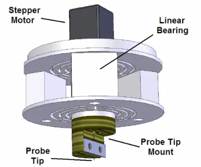
The three components of the linear stage – the stepper motor, the linear bearing, and the probe tip mount are shown in their assembled positions in Figure 3.3.
Figure 3.3: The linear stage includes the stepper motor, linear bearing, probe tip mount, and probe tip.
3.4 The Linear Bearing
Elastic Range (5mm) Axial Stiffness (Fmotorfriction/Z<k<Fmax/Range) Parastic Radial Motion (<1nm) Maximum Deflection X Axial K X Non-Axial K X
Table 3.4. The functional requirements and design parameters for the linear bearing.
The linear bearing serves three functions – (1) to attenuate parasitic motions due to inevitable activation misalignment from the stepper motor, and (2) to preload the stepper motor to prevent backlash in order to ensure a constant step size while (3) facilitating linear actuation over an appropriate range. The FR-DP correlation is shown
in Table 3.4. There are equal numbers of functional requirements and design parameters, and the correlation is 1:1. This allows for straight-forward design.
The linear bearing subassembly is made up of two diaphragm flexures separated by spacers. The linear bearing subassembly is shown in Figure 3.4a. The linear bearing must maintain relative compliance for axial displacements while providing stiffness for radial displacements and out-of-plane rotations, in order to attenuate non-linear actuation gains. Implementation of two separated diaphragm flexures specifically amplifies the out-of-plane torsional stiffness. To first order, the separation amplifies stiffness by
z r d b K r K d G ⋅ ⋅ ⋅ ⋅ = ≡ 2 3
τ
τ
(3.4)compared to a single diaphragm flexure, where G is the stiffness ratio, τband τdare defined as the out-of-plane torsional stiffnesses of the linear bearing and a single diaphragm flexure, d is the separation, r is the radius of the center stage, and Kr and Kz are respectively the radial and the axial stiffnesses.
Figure 3.4a. The linear bearing preloads the stepper motor and attenuates parasitic motions. It is composed of two diaphragm flexures separated by half inch spacer.
The flexures were water-jet from 0.032” aluminum sheet, and the spacers from 0.5” aluminum. A finite element analysis (FEA) diagram of the displacement of one flat flexure under load is shown in Figure 3.4b. This FEA predicted the axial stiffness of each flexure at 126.6 N/m, yielding 253.2 N/m. Over the estimated travel of the linear actuator of 5 mm, this configuration requires a maximum actuator force of 1.25 N. The radial stiffness per flexure is 3846.2 N/m, yielding 7692.3 N/m as an assembly. The axially, the subassembly is more than 30 times more compliant axially than it is radially. The out of plane torsional stiffness is 0.87 N*m/rad for a single flexure, yet 48.8 N*m/rad as an assembly. Using this geometry, a torsional stiffness gain of 56 is achieved.
Figure 3.4b: This diaphragm flexure is compliant in the z-direction, but stiff in the plane.
3.5 The Stepper Motor
The stepper motor must be able to have a total range of over five millimeters for the initial approach and must also step in increments smaller than the vertical scanning range of the HexFlex (about three microns), including vibrations induced by stepping. The stepper must also be rated with enough force to deflect the linear preload bearing to a
deflection of five millimeters, which corresponds to a force at least 1.25 N with the current linear bearing design. The FR-DP diagram is shown in Table 3.5.
Range (> 5mm) Step Size (Move to Z<2um) Force Output (> 1.25N) Range (>5mm) X Step (<2um) X Force (>30N) X
Table 3.5: The FR-DP matrix of the stepper motor.
The linear actuator was purchased from Haydon Switch and Instrument. It is a 21000 series size 8 captive style hybrid actuator (Part Number 21H4U-2.5-904), and it has a resolution of 1.5 microns and a travel of nine millimeters. It is also capable of outputting a continuous 44.5 N force. All of the specifications exceed the functional requirements for the stepper motor. A photograph of the linear actuator is shown in Figure 3.5. The accompanying driver is 40105 Bipolar Chopper Drive and will be introduced in section 3.8, System Electronics.
Figure 3.5: The Haydon hybrid captive shaft linear actuator is capable of a 1.5 um step size with a 9 mm stroke and thrust of 44.5 N [8].
3.6 The Probe Tip Mount
The probe-tip mount must house the 0.25 mm diameter probe-tip and provide current reliably while electrically and thermally isolating the tip from the rest of the assembly. The tip should also be easily removable. An FR-DP diagram is shown in Table 3.6. The 1:1 correlation shows that the probe tip mount can also be designed axiomatically. Electrical Connection Tip Replacement Electrical & Thermal Isolation Clamp Plate Material X Clamp Plate X Base Material Selection X
Table 3.6: The FR-DP matrix of the probe tip mount.
Phenolic resin is an ideal material because of its favorable electrical and thermal properties. Phenolics are the result of polymerization between resin and a base material that might be paper, glass or cotton [9]. Garolite XX/XXX is a paper-based phenolic and was chosen for its electrical and thermal insulation and small thermal expansion.
Garolite XX/XXX is rated with a thermal conductivity of 0.288 W/m/K, which is just less than delrin at 0.36 W/m/K. This type of Garolite also boasts a coefficient of thermal expansion of 1.4 x 10⁻⁶ per degree Celsius [10]. Most metals have a coefficient of thermal expansion of about 10 – 30 x 10-6 per degree Celsius [11]. Small thermal expansion reduces unwanted motions of the tip due to thermal strains.
Figure 3.6: The probe-tip mount is made of Garolite, a paper phenolic material resistant to thermal expansion and electrically insulating. Current will be supplied to the tip via
the aluminum clamping plate.
The probe-tip mount design is shown in Figure 3.6. This design is simple, having only two parts besides the tip and fasteners. An aluminum plate held by two bolts (not shown) presses the probe-tip shaft into a groove in the phenolic. Electrical contact is transmitted from a wire to one of the bolts, through the aluminum plate, and into the tip. Removing the tip is as easy a loosening one of the bolts and pulling on the aluminum tab shown on the right.
3.7 Kinematic Coupling
The kinematic coupling serves to reposition the tip accurately and repeatably above the sample when the top and bottom halves are separated for tip maintenance or sample placement and removal. The kinematic coupling must reposition the tip within the size of the sample which is on the order of millimeters. The kinematic coupling must also be very stiff to increase the natural resonance frequency of the device as a whole and
prevent low frequency vibration propagation throughout the device. The FR-DP diagram is shown in Table 3.7. Repeatability (<1mm) Vibrational Isolation Plate Interfaces X Material & Geometry X
Table 3.7: The FR-DP matrix of the kinematic coupling
The kinematic coupling is a Maxwellian three V-groove style mount [12]. A magnetic preload between a magnet and a steel bar is applied near each contact to ensure consistent preloading. The kinematic coupling is shown in Figure 3.7. The kinematic coupling was designed and fabricated by Dariusz Golda.
Figure 3.7: The kinematic coupling.
3.8 System Electronics
The HexFlex driver is a combination of six current controllers that supply current to each of the six coils on the actuator paddles. The amount of current is dictated by the
control system which is calibrated to intake desired positions in nanometers and rotations in degrees and output the corresponding currents. The gains for each coil with respect to each input are adjusted in the software when each device is calibrated. The HexFlex driver is shown in Figure 3.8a. The driver for the HexFlex was designed and fabricated by Dariusz Golda.
Figure 3.8a: The HexFlex driver created by Dariusz Golda. Each of these modules controls one actuator paddle on the HexFlex. Three are needed for full control.
The stepper motor runs on the 40105 Bipolar Chopper Drive distributed by
Haydon Switch and Instrument. The Chopper Drive runs on a 24 – 40 volt power supply. The two digital to the drive are step direction command and a pulsed step command. The drive sends the appropriate signal to the stepper motor to achieve the corresponding motion. The Chopper Drive is shown in Figure 3.8b.
Figure 3.8b: The stepper motor’s 40105 Chopper Drive [8].
One of the most important electronic components is the ammeter which is used for the closed loop feedback control of the HexFlex as it moves the surface relative to the tip. The ammeter chosen was the Keithley 6485 picoammeter shown in Figure 3.8.c [13]. This ammeter has a resolution of ten femtoamps and a sampling rate of one kilohertz.
3.9 The Control System
Two main software tools are used to control the system. The control system is a MATLAB SimuLink based program. The necessary user interface was created
graphically in Control Desk layout.
Figures 3.9a: This Simulink program controls the stepper motor and the HexFlex positions based on the tunneling current output in order to obtain and maintain tunneling.
The process of obtaining the appropriate gap is contained in a software approach algorithm which alternates between stepping the linear actuator and scanning the
remaining gap with the HexFlex. A diagram representation of this algorithm is presented is made explicit the Simulink diagram contained in Figure 3.9a. If the tip is not within range of the HexFlex, the linear actuator will step the tip closer. When the tip is brought to within the range of motion by the linear actuator and the HexFlex closes the remaining
control monitoring the tunneling current. Tunneling current data is measured with the Keithley picoammeter. All of the controls necessary for the user are easily accessible in the Control Desk GUI. An image of the GUI in use is shown in Figure3.9b. Tunneling current is the only needed feedback to the control system. The control system maintains a set amount of tunneling current and records the vertical output necessary as the sample is scanned horizontally in a raster-scan pattern. The raster-scan is used to create a 3D image.
Figure 3.9b: The GUI for the control system is in Control Desk
For EPL, a scan is implemented to assure that the surface is relatively flat, and then the rest of the motions are done without tunneling current feedback. The sample is lowered 50 nm from the point where tunneling current was measured, and the horizontal positioning of the sample is relative to that point. The tip-sample voltage is pulsed at each point where material removal is desired. After the EPL operations are complete, the
HexFlex raises the sample to the point where tunneling current is again detected and scans the surface as before to confirm the features.
3.10 System Modeling
Finally, after designing all of the components of the system, the system as a whole must be dynamically modeled. Differential models of the system dynamic response show that there are several failure modes of the design, even if each of the components function as specified. These failure modes reveal some sensitive parameters within the
implementation of the design.
Several failure modes were confirmed by simulation of a commanded sample trajectory relative to the probe tip and modeling the dynamic response of the sample induced by the second order mechanical dynamics of the HexFlex as well as the electrodynamic capacitance forces induced via the charge between the sample and tip. Capacitive forces and elastic forces balance to form two equilibrium planes. A steady equilibrium plane generally lies close to the commanded position of the sample. Another unsteady equilibrium, however, exists between the steady equilibrium plane and the tip. The main factors that determine position of these equilibrium planes is are the bias voltage and the bluntness of the tip. The higher the voltage and the blunter the probe tip, the closer these equilibriums lie. If the sample penetrates the unsteady equilibrium plane, it will crash into the tip.
The first possible failure mode confirmed in simulation is illustrated in Figure 3.10a. An approach that brings the sample too close to the tip too quickly will overshoot both steady and unsteady equilibriums and crash the sample into the tip. This failure mode is sensitive to the damping of the HexFlex and the approach speed.
Figure 3.10a: If the sample is commanded to approach the tip too rapidly, the overshoot will pass the unsteady equilibrium plane and crash the sample into the probe tip [Image
courtesy of Robert Panas, 2006].
A second failure mode occurs if the sample is brought too close to the unsteady equilibrium plane. Even if approaching slowly, remaining vibration may drive the sample past the unsteady equilibrium plane and crash the sample into the surface. This failure mode is sensitive to the proximity of the steady and unsteady equilibrium planes. This failure mode can be avoided by reducing the capacitive forces by lowering the voltage, using a sharper tip, or maintaining a more conservative gap. The second failure mode is shown in Figure 3.10b.
0 0.02 0.04 0.06 0.08 0.1 0.12 0.14 0.16 0.18 0.2 0 10 20 30 40 0 5 10 Location Command Steady Equib Unsteady Equib Voltage Location Command Steady Equib Unsteady Equib Voltage Time (seconds) T ip t o S u rf ac e se p ar at io n ( n m ) V o lt ag e (V )
Figure 3.10b: Another failure mode is bringing the sample too close to the tip, even gradually. Residual vibrations may cause the sample to cross the unsteady equilibrium
plane and crash the sample into the tip [Image courtesy of Robert Panas, 2006].
EPL operation also imposes risks. A third possible failure mode may present itself when pulsing the voltage for EPL. An increase in voltage draws the unsteady and steady equilibrium planes together. If they become too close, then the sample can crash into the probe tip. This failure mode is sensitive to the speed and magnitude of the pulsed voltage, and the EPL gap distance as well as the tip bluntness. Figure 3.10c shows a successful EPL simulation, but also the increase in risk when pulsing the voltage.
0 0.02 0.04 0.06 0.08 0.1 0.12 0.14 0.16 0.18 0.2 0 5 10 15 0 5 10 Location Command Steady Equib Unsteady Equib Voltage Location Command Steady Equib Unsteady Equib Voltage Time (seconds) T ip t o S u rf ac e se p ar at io n ( n m ) V o lt ag e (V )
Figure 3.10c: When pulsing the voltage for EPL, the unsteady equilibrium plane can extend much closer to the steady equilibrium plane [Image courtesy of Robert Panas,
2006].
Properly avoiding these three failure modes among others is necessary in successful implementation of the device.
CHAPTER 4
Characterization
After design, manufacture, and assembly, each new subassembly and the system as a whole were tested and characterized.
4.1 Linear Stage Characterization
The major characteristic necessary for characterization with regards to the tip linear actuation assembly is the resolution and the consistency of actuation. The assembly was characterized via repeatedly stepping the flat stage face toward a capacitance probe over several hundred steps. The assembly was found to have an
average step size of 1.39 microns with a standard deviation of 0.19 microns. A histogram of the step sizes is shown in Figure 4.1. The linear actuator was shown to function within specifications. The preload bearing effectively increased step size repeatability.
0.9 1.0 1.1 1.2 1.3 1.4 1.5 1.6 1.7 1.8 1.9 2.0 0 2 4 6 8 10 12 14 N u m b e r o f S te p s
Step Size (microns)
Step Size Histogram
Figure 4.1: A histogram of the linear stage step size
4.2 System Background Noise
Good understanding of electronic system noise is essential when dealing with closed loop feedback based on current signals on the order of nano and picoamps. System electronic noise data was gathered and characterized in order to assess the large contributors of the noise and develop an attenuation strategy if necessary. The resultant noise decomposition is shown in Figure 4.2. The largest contributor to the noise when the stepper motor driver is not powered up is a signal at roughly 60 hz which corresponds to lights in the room and other neighboring devices that utilize building power supply. However, another larger peak of noise appears when the stepper motor driver is powered. The new peak is at 440 hz. Since this peak is well above the natural frequency of the HexFlex of 120 hz, this noise can be filtered out with a low pass filter with little effect on the speed of the device.
Figure 4.2: The electronic system noise decomposition with all components on except the stepper motor driver is shown in the top noise spectrum. The noise of the system will
all electronic components on is shown below.
4.3 Establishing Tunneling Current
With the linear actuation stage functioning as specified, the approach algorithm may be tested. Several tests were initially run with a bias voltage of two volts and PID closed loop control gains of 1e-6, 5e-4, 1e-7. A few of these test resulted in semi-stable tunneling current which implies that constant gap of less than five microns is being maintained. The most successful initial test with this configuration is shown in Figure 4.3a. Although tunneling seems to be somewhat maintained over about ten seconds, the tunneling current is very unsteady and the sample eventually crashed into the tip and the tunneling current was saturated. This necessitated more experimentation with the system.
Figure 4.3a: The most successful initial tunneling experiment showed semi-sustained tunneling over about ten seconds, but lost control shortly thereafter.
Reconstruction of the device over several months and replacement of the former picoammeter with the Keithley 6485 picoammeter reduced the system noise significantly and adjustment of the tunneling current voltage and PID controller gains aided tunneling stability. A subsequent sample of maintained tunneling is shown in Figure 4.3b.
Tunneling could be repeatedly achieved and maintained for long periods of time.
Although the figure only shows a 20 second time interval, tunneling could be maintained for several minutes. The limiting factor became overheating of the HexFlex driving current amplifiers rather than control issues. 1e-2, 1e-1, and 1e-7 worked well as the respective PID controller gains.
Despite steady tunneling however, noticeable drift was present. The experiment shown in Figure 4.3b is among one of the experiments with the least drift. The drift is thought to be thermal because of its large time scale. This is very difficult to control
because the HexFlex actuator paddles dissipate heat when currents ore run through them. The amount o current that each paddle draws varies with commanded position of the actuator. Therefore, as the HexFlex maintains steady tunneling current via actuation, it dissipates varying amounts of heat impeding the establishment of a thermal equilibrium. This problem cannot be easily solved in this design, but since the time scales of the thermal drift are so large, it may be possible to do a STM scan of the surface very quickly before temperatures gains can be propagated throughout the device.
Figure 4.3b: Subsequent experiments showed stable tunneling current maintained for over 20 seconds. There still remains notable drift.
4.4 STM Scanning
Over short timescales it may be possible to obtain useful STM scans of a surface with the current configuration despite thermal drift. This was attempted with limited
success. One example of a surface scan is shown in Figure 4.4a. The commanded Z output over time is shown in Figure 4.4b. It appears that there is a small valley with a large rolling knoll that forms as the scan progresses in the X direction.
Figure 4.4a: A raster scan of the surface or the sample.
However, closer examination of the data collected suggests that the contours visible in the raster scan are little more than thermal drift. The measured tunneling current and the commanded Z output for this scan are shown in Figure 4.4b. Note that the drift in the commanded Z over time is very similar to the characteristics shown in Figure 4.3b over time and seems independent of motion in the Y direction. Also looking at the scan from other angles reveals interesting characteristics. Two plots are shown in Figure 4.3c. The first is an X-Y plot of the scan for reference. The second is and X-Z view of the scan. This effectively hides all most of the features in Y. The scan
progresses in time as the X coordinate increases. The fact that this bears almost exactly the same shape as the commanded Z vs. time plot shown in Figure 4.3b and X increases
with time insinuates that the change over X is actually thermal drift rather than surface contour.
Figure 4.4b: The measured tunneling current (above) and commanded Z (below) over time
Figure 4.3c: The X-Y plot (left) shows the commanded raster scan trajectory. The X-Z plot suggests that the change in Z to needed to maintain constant tunneling current is independent of the Y coordinate.
CHAPTER 5
Conclusions
Under the current configuration, the system is capable of scanning a surface and maintaining tunneling current. However, thermal drift induced by the environment and HexFlex actuator paddles impedes STM scanning over time scales larger than a second. It may be possible to attenuated the effects of this drift through several methods:
(1) Performing surface scans over shorter time scales (2) Filtering the drift with a high-pass filter
(3) Accounting for drift with an extra sensor such as a capacitance probe (4) Developing more robust current amplifiers capable of driving the HexFlex
long enough to allow the system to equilibrate thermodynamically while maintaining tunneling.
Even so, with an estimate of the surface position within even ten nanometers of thermal drift uncertainty, it may be possible to perform EPL with the current system. Yet without STM functionality, the machined features would be difficult to locate, and thus EPL has not been attempted. Further development of the thermodynamic stability of this device is recommended.
References
[1] Golda, Dariusz. “Electromagnetically-Actuated Meso-Scale Nanopositioners”. Doctorate Thesis Proposal. 2005.
[2] Culpepper, Martin L. and Golda, Dariusz. “A Scalable Six-Axis
Electromagnetically-Driven Nanopositioner For Nanomanufacturing”. 2006. [3] Labuz, James. “Design. Fabrication, and Testing of a Three-Dimensional
Monolithic Compliant Six-Axis Nanopositioner”. MIT ME BS Thesis. June, 2006.
[4] Than, Ker. “Nano-Pen Writes in Tiny Letters”. LifeScience.com. 2006.8.25.
http://www.livescience.com/imageoftheday/siod_050824.html#text accessed 2006.9.25.
[5] IBM Almaden Research Center Visualization Lab. “Scanning Tunneling Microscopy”. www.almaden.ibm.com/vis/stm/images/stm.gif accessed 2006.10.28.
[6] Anderson, Gordon. “A six-degree of freedom flexural positioning stage”. MIT ME MS Thesis. February, 2003.
[7] Culpepper, Martin L. “Kinematics and Elastomechanics of Flexure-based Machines”. 2.672 Lecture 9. Fall, 2006. Pages 6 and 18.
[8] Haydon Switch and Instrument. “40105 Chopper Drive Manual”.
www.haydoneurope.com/drives/chopper/40105/Chopper.pdf, and
www.haydoneurope.com/drives/chopper/40105/HaydHybridDrivers.pdf accessed 2007.4.27.
[9] Wikipedia. “Phenolic Resin”. http://en.wikipedia.org/wiki/Phenolic_resin accessed 2006.10.28.
[10] K-mac Plastics. “LaminatesTechnical Data”.
phenolic-sheets-rods-tubes.com/data%20sheets/technical-data.htm accessed 2007.4.30.
[11] MatWeb: Material Property Data. “Online Material Datasheet”.
www.matweb.com accessed 2007.4.30.
[13] Keithley Instruments. “Model 6485 5-1/2 digit Picoammeter with 10fA Resolution”. www.keithley.com/applications/computer/?mn=6485 accessed 2007.5.10.
[14] MIT News Room. “MIT's HexFlex manipulates the nanoscopic”.
September 30, 2003. web.mit.edu/newsoffice/2003/hexflex.html accessed 2007.2.25.
![Figure 1.1: Dariusz Golda’s original HexFlex based EPL device. [Photo courtesy Dariusz Golda, 2006]](https://thumb-eu.123doks.com/thumbv2/123doknet/14686292.560339/15.918.199.721.107.452/figure-dariusz-golda-original-hexflex-device-courtesy-dariusz.webp)