Deep Sea Research Submarine
LCDR Jeff Woertz
LT Erik Oller
LT Erek Withee
February 1, 2002
Massachusetts Institute of Technology
Cambridge, MA
Executive Summary
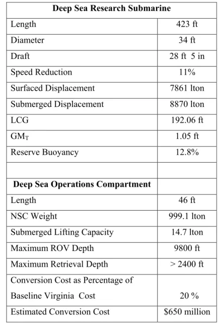
The Deep Sea Research Submarine (Figure 1) is a modified VIRGINIA Class
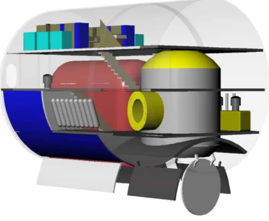
Submarine that incorporates a permanently installed Deep Sea Operations Compartment (Figure 2). Table 1 summarizes the characteristics of the Deep Sea Research Submarine and the Deep Sea Operations Compartment. The compartment, inserted as a 46-ft parallel midbody section, carries a heavy lift system capable of retrieving a 15-ton object (submerged weight) from depths greater than 2400 ft. A 26-ft L x 22-ft H x 12-ft W payload bay external to the pressure hull is used to house the object for transport. This payload bay also serves as a fully functioning mid-ship Main Ballast Tank. The compartment is supported by a combination of ship service and compartment-specific auxiliary systems.
Figure 1. Deep Sea Research Submarine
The compartment also contains a 16 ft diameter x 17 ft high Remotely Operated Vehicle (ROV) Chamber outfitted with a Triton ZX ROV capable of excursions to depths of 9800 ft. The ROV Chamber permits dry access to the ROV for maintenance and mission-related tasks. The control center for the lift system and the ROV and a "mission flexible" space are located on the compartment's upper deck
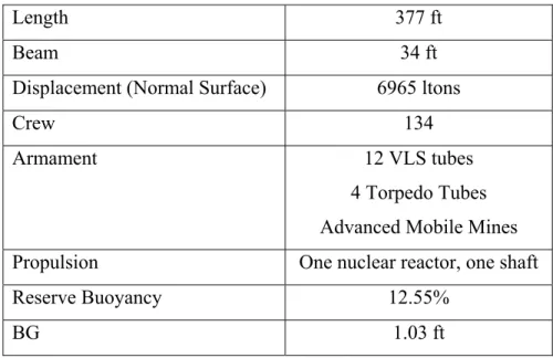
Table 1. Deep Sea Research Submarine and Deep Sea Operations Compartment Principle Characteristics
Deep Sea Research Submarine
Length 423 ft
Diameter 34 ft
Draft 28 ft 5 in
Speed Reduction 11%
Surfaced Displacement 7861 lton Submerged Displacement 8870 lton
LCG 192.06 ft
GMT 1.05 ft
Reserve Buoyancy 12.8%
Deep Sea Operations Compartment
Length 46 ft
NSC Weight 999.1 lton
Submerged Lifting Capacity 14.7 lton
Maximum ROV Depth 9800 ft
Maximum Retrieval Depth > 2400 ft Conversion Cost as Percentage of
Baseline Virginia Cost 20 % Estimated Conversion Cost $650 million
Table of Contents
Deep Sea Research Submarine
... iExecutive Summary ... ii
Table of Contents... iv
List of Tables ... vi
List of Figures ... vii
1.0 Mission Need ... 1
1.1 Defense Guidance and Policy. ... 1
1.2 Adversary Capabilities Analysis... 1
1.3 Current United States Capability Assessment ... 2
1.4 Mission Need ... 3
1.5 Recommended Alternatives... 4
2.0 Design Requirements and Plan ... 4
2.1 Required Operational Capability ... 4
2.2 Concept of Operations/Operational Scenarios/Performance Assessment Models ... 5
2.2.1 Scenario 1: Locate, Identify and Recover an Object of Interest ... 5
2.2.2 Scenario 2: Conduct Scientific Research... 6
2.3 Goals, Constraints and Standards ... 6
2.4 Design Philosophy and Decision Process... 8
3.0 Concept Exploration ... 9
3.1 Baseline Concept Design ... 9
3.2 Concept Ship Variants ... 9
3.2.1 Addition of a Parallel Mid-Body (PMB) ... 10
3.2.2 Addition of Module Forward of the Sail... 10
3.2.3 Bow Reconfiguration ... 10
3.2.4 Use of Appendages ... 11
3.3 Variant Assessment and Trade-off Studies... 11
3.4 Final Baseline Concept Design... 12
4.0 Feasibility Study and Assessment... 14
4.1 Design Definition... 14
4.1.1 Ship Geometry ... 14
4.1.2 ROV and Equipment... 15
4.1.3 Lift Mechanism and Equipment... 18
4.1.4 Combat Systems/C4ISR... 19
4.1.5 Propulsion, Electrical and Auxiliary Systems... 20
4.1.6 Survivability and Signatures ... 20
4.1.7 Manning ... 21
4.1.8 Arrangement ... 22
4.1.9 Structural Design ... 29
4.1.10 Weights and Stability... 37
4.2 Performance Analysis ... 43
5.0 Design Conclusions ... 46
5.1 Summary of Final Concept Design... 46
5.1.1 ROV Operations... 47
5.1.2 Heavy Lift Capability ... 47
5.2 Final Conversion Design Assessment... 47
5.3 Areas for Further Study ... 48
Acknowledgments... 49
References... 50
Appendices... 51
A. Mission Need Statement ... 2
1. Defense Planning Guidance Element ... 2
2. Adversary Capabilities Analysis... 2
3. Mission Analysis... 3
4. Potential Non-Materiel Alternatives... 5
5. Potential Materiel Alternatives ... 5
6. Constraint... 6
B. MIT XIII MathCAD Submarine Model... 1
C. TRITON ZX Parameters... 2
D. Structural Design ... 1
ROV Chamber Shell Analysis ... 2
Payload Bay Shell Analysis... 11
Payload Bay Lateral Wall Analysis ... 20
Payload Bay End Wall Analysis... 28
Forward Watertight Bulkhead Design ... 36
E. POSSE Section Calculations... 45
F. Bending Moment Calculation for Asymmetric Hull Section ... 46
G. Detailed Weight and Moment Data ... 1
List of Tables
Table 1. Deep Sea Research Submarine and Deep Sea Operations Compartment
Principle Characteristics ... iii
Table 2. DSRS Goals ... 6
Table 3. Design Requirements... 8
Table 4. VIRGINIA Class Submarine Characteristics ... 9
Table 5. DSRS Design Summary... 12
Table 6. Deep Sea Operations Compartment Characteristics... 15
Table 7. TRITON ZX Characteristics... 16
Table 8. ROV Control Equipment Data... 18
Table 9. Characteristics of a Representative Heavy Lift Cable ... 19
Table 10. Estimated DSOC Power Requirements ... 20
Table 11. Bending Moment Due to Hydrostatic Pressure ... 31
Table 12. Moments of Inertia about the Neutral Axis ... 31
Table 13. ROV Chamber Failure Mode Stress Ratio Summary... 33
Table 14. Payload Bay Shell Head Failure Mode Stress Ratio Summary ... 34
Table 15. Payload Bay Lateral Wall Failure Mode Stress Ratio Summary... 35
Table 16. Payload Bay End Wall Failure Mode Stress Ratio Summary ... 35
Table 17. DSOC Weight Summary ... 37
Table 18. Seawater Density Assumptions ... 41
Table 19. Lead Solution Summary ... 41
Table 20. Ship Weights and Centers... 42
Table 21. Extreme Load Case Stability Parameters... 43
Table 22. Normal Surface Condition Stability Parameters... 43
Table 23. Cost Estimating Parameters ... 45
Table 24. ROV and Support Equipment Cost... 45
Table 25. Deep Sea Research Submarine and Deep Sea Operations Compartment Characteristics... 46
List of Figures
Figure 1. Deep Sea Research Submarine... ii
Figure 2. Deep Sea Operations Compartment ... ii
Figure 3. Final Baseline Concept Design ... 13
Figure 4. Parallel Mid-Body Addition Showing Internal Arrangements and Doors. ... 14
Figure 5. TRITON ZX ROV... 16
Figure 6. ROV Control Consoles in a Typical Arrangement... 17
Figure 7. High Voltage Transformer Unit and High Voltage Junction Box... 18
Figure 8. Power Distribution Unit ... 18
Figure 9. Lift Frame... 19
Figure 10. A Submarine Torpedo Room Berthing Pod being loaded into a Dutch submarine... 21
Figure 11. Payload Bay Internals... 22
Figure 12. ROV Chamber Internals ... 23
Figure 13. Plug Length Tradeoff Space... 24
Figure 14. DSRS Profile ... 25
Figure 15. DSOC Upper Level ... 26
Figure 16. DSOC Middle Level... 27
Figure 17. DSOC Lower Level... 28
Figure 18. DSOC Tankage Level... 29
Figure 19. DSOC Cross-Section... 30
Figure 20. ROV Chamber Scantlings ... 33
Figure 21. Payload Bay Scantlings ... 36
Figure 22. Longitudinal Balance Corrections... 38
Figure 23. Equilibrium Polygon ... 40
Figure 24. Percentage Change in Baseline VIRGINIA Submarine Cost due to DSRS Conversion ... 45
1.0 Mission Need
1.1 Defense Guidance and Policy.
This Mission Need Statement (MNS) provides requirements for a multi-mission submarine with deep-sea research capability for the 21st Century battle force vision. Through technology investment and insertion, the Deep Sea Research Submarine (DSRS) will be able to perform deep-sea research missions in addition to all the missions of a fast attack submarine. This submarine must operate wherever required to enable joint
maritime expeditionary force operations, project precise strike power ashore, and conduct scientific and military research missions. The mission capabilities must be fully
interoperable with other naval, interagency, joint and allied forces.
This unclassified MNS in part addresses Joint Vision 2020, published in June 2000. This documentoutlines the vision for creation of a force that “is dominant across the full spectrum of military operations – persuasive in peace, decisive in war, preeminent in any form of conflict.” Additionally, the document addresses “the need to prepare now for an uncertain future”.1
The deep-sea research functions described in this MNS address the requirements set forth in Joint Vision 2020 to have “access to and freedom to operate in all domains”2 as well as to support the information superiority which has been regarded as a key enabler of victory.3
This MNS should guide 21st century DSRS design, research, development and acquisition program decisions, service and joint doctrine, and cooperative efforts with U.S. allies.
1.2 Adversary Capabilities Analysis
As a result of the 2001 Quadrennial Defense Review, the basis of defense planning has been shifted from a threat-based model to a capabilities-based model. The
1. Chairman of the Joint Chiefs of Staff, Joint Vision 2020 (Washington, D.C.: US
capabilities-based model focuses on how an adversary might fight instead of who that adversary might be. This model recognizes that planning for large wars in distant theaters is not sufficient. The United States must also plan for adversaries who will rely on surprise, deception and asymmetric warfare to meet their objectives.4 Adversary capabilities will include asymmetric approaches to warfare that include terrorism and weapons of mass destruction.
In the past, the large distances between adversaries and the United States have
provided a significant level of protection. As the events of September 11, 2001 illustrate, the U.S. can no longer rely upon this geographic protection. The rise of international travel and trade has made even the United States homeland vulnerable to hostile attack.5 Makers of national strategy will need to consider the rise and decline of regional powers. Some of these states are vulnerable to overthrow by radical or extremist internal forces. Many of these states have large armies and the capability to possess weapons of mass destruction. 6 In some states, the governments are unable to prevent their territories from serving as sanctuaries for terrorists and criminals which may pose threats to the safety of the United States. In these cases, “threats can grow out of weakness of governments as much as out of their strength.”7
Asymmetric warfare, reduced protection from geographical distances, and
vulnerabilities of foreign governments result in the need for the United States to maintain the ability to gather intelligence in all forms and in all areas of the globe. A key element in intelligence gathering is the ability to recover objects from the sea floor.
1.3 Current United States Capability Assessment
The purpose of the deep-sea research submarine is to augment the fleet by providing an autonomous deep-sea research platform with long-term station-keeping ability. The principal deep-sea research submarine of today’s Navy is the NR-1. This vessel was launched in 1969 and is among the oldest submarines in the Navy. NR-1’s missions have
4. Department of Defense, Quadrennial Defense Review Report (Washington, D.C.: US
Government Printing Office, 2001). iv
5. Ibid., 4 6. Ibid. 7. Ibid., 5
included search, object recovery, geological survey, oceanographic research, and installation and maintenance of underwater equipment.8 NR-1 continues to provide a valuable service to the Navy and many research and educational institutions, but a replacement must be obtained in order to perform these missions after the end of NR-1’s design life.
1.4 Mission Need
The roles of a future DSRS will include the following principal areas of naval warfare and research:
A. Intelligence, Surveillance, and Reconnaissance (ISR). A submarine’s stealth makes it an ideal platform because the submarine can slip undetected into areas that are denied to surface and air platforms. To enhance its ability to accomplish this mission, the submarine must have the appropriate sensors, possibly including unmanned underwater vehicles (UUV’s) and unmanned air vehicles (UAV’s).9
B. Sea Control. A submarine’s stealth again makes it a good platform for being the first to enter hostile areas. The future submarine should have the ability to locate and possibly neutralize diesel electric or air-independent propulsion submarines and mines. 10
C. Land Attack. Submarines have already proven their ability to carry out strike operations. The importance of this mission will continue to increase because the submarine allows much more flexibility in the selection of the launch point. Launching missiles close to the enemy coastline, perhaps inside the defensive air umbrella, results in shorter flight times, greater surprise, and increased accuracy.11
D. Special Operations Forces (SOF) Support. SOF mission support includes transit to and from the launch site, launch and recovery of SOF, and shore and surface fire support.
8. United States Navy Fact File: NR-1 Deep Submergence Craft. 1999.
www.chinfo.navy.mil/navpalib/factfile/ships/ship-nr1.html
9. Edward C. Whitman “ Submarines in Network Centric Warfare.” Seapower (July,
E. Oceanographic Sciences. The submarine will provide support for research in a variety of fields including Physical Oceanography, Ice Science, Geology/Geophysics, Marine Biology, Atmospheric Science, Ocean Engineering, Chemical Oceanography, Maritime Archeology, and Environmental Science.
F. Object Manipulation and Recovery. The submarine will be able to locate, manipulate, and recover objects of military or scientific interest from the ocean floor. The submarine may utilize remotely operated vehicles (ROV’s) to perform these missions.
Appendix A contains more detailed information regarding the mission need.
1.5 Recommended Alternatives
Potential alternatives for meeting the need described above include: A. Design of an entirely new class of submarine.
B. Modification of an Improved Los Angeles Class Design to meet the mission requirements.
C. Modification of an Ohio Class Design to meet the mission requirements. D. Modification of a Seawolf Class Design to meet the mission requirements. E. Modification of a VIRGINIA Class Design to meet the mission requirements. The VIRGINIA Class Design Modification is selected for further investigation.
2.0 Design Requirements and Plan
2.1 Required Operational Capability
The DSRS must be capable of supporting all VIRGINIA Class Submarine combat missions and a variety of military and scientific research missions. These missions require the launch and recovery of an ROV, the ability to perform heavy lifts, and possibly the ability to launch expendable UUV’s. These missions also require analysis and berthing facilities for embarked research mission personnel.
2.2 Concept of Operations/Operational Scenarios/Performance Assessment
Models
The concept of operations for the DSRS includes combat missions and a variety of military and scientific research missions. Combat missions will not be affected by this study and will not be discussed here. The research missions of the DSRS are related to those currently performed by other research submarines such as NR-1 and principally include object recovery and data acquisition. Two potential scenarios for these missions follow.
2.2.1 Scenario 1: Locate, Identify and Recover an Object of Interest
The first scenario includes the location, identification, and recovery of an object of interest from the ocean floor. The DSRS will stealthily proceed to the search area and commence searching for the object. The search will use a variety of sensors including side scan sonar and visual. These sensors will be located on the DSRS, UUV’s, and/or an ROV. Once the object has been located the identity of the object will be confirmed and the recovery process will begin.
The ROV will be used to inspect the object for connection points, physical integrity and potential risk to the DSRS. The ROV may need to manipulate the object to render it safe for transport or to disable any threat to the DSRS. The ROV may need to reposition the object to enable attachment to the lifting frame. The ROV will install four lift points on the object. The ROV may use a specialized lifting harness for the object or existing features on the object. Once the object is ready for lift the ROV will return to the submarine.
The DSRS will lower the lift frame to the object. The lift frame will be remotely controlled from the submarine. The lift frame will have thrusters, cameras and lights for proper positioning. The lift frame arms will attach the lift points on the object to the lift points on the lift frame. The lift mechanism will lift the object into the DSRS for transportation to its ultimate destination.
2.2.2 Scenario 2: Conduct Scientific Research
The variety of possible scenarios for scientific research is infinite. This discussion is a simplified approach to meeting the needs presented in those scenarios. The DSRS will stealthily proceed to the region of interest. The ROV will be deployed to obtain samples or make observations at deep depths and on the sea bottom. Scientific sensors attached to the lifting frame will be lowered into the water to make other measurements and
observations.
2.3 Goals, Constraints and Standards
Table 2 shows the goals for the DSRS.Table 2. DSRS Goals
Goals
Science and Research Mission Depth 2400 ft Maximum Lift Capability 33,000 lb VIRGINIA Class Speed Reduction 15% The MNS provides the following constraints.
A. Architecture - The ship design must employ a total ship
architectural/engineering approach that optimizes life cycle cost and performance, minimizes operating conflicts, permits rapid upgrade and change in response to evolving operational requirements, and allows computational and communication resources to keep technological pace with commercial capabilities. More specifically, this implies physical element modularity; functional sharing of hardware; open systems information architecture; ship wide resource management; automation of Command, Control, Communications, and Computers (C4I), and navigation functions; integrated ship wide data management; automation and minimization of maintenance and administrative functions; and embedded training.
B. Design - Consideration should be given to the maximum use of modular designs in the research vessel’s infrastructure. Emerging technologies must be accounted for during the developmental phase. Since communication and data systems hold the greatest potential for growth, and therefore obsolescence, their installations must be
modularized as much as possible to allow for future upgrades. Systems onboard must use standard man-to–machine interfaces. The man-to-machine interfaces should be
consistent with existing user-friendly systems.
C. Personnel - The ship must be automated to a sufficient degree to realize significant manpower reductions in engineering, ship support and watchstanding requirements. Preventive maintenance manpower requirements must be reduced by incorporating self-analysis features in equipment designs and by selecting materials and preservatives that minimize corrosion.
A. Operational Constraints.
1. The DSRS must remain fully functional and operational in all
environments, whether conducting independent or force operations; in heavy weather; or in the presence of electromagnetic, nuclear, biological and chemical contamination.
2. The DSRS must provide ROV launching and recovery facilities. 3. The DSRS must be able to operate in U.S., foreign, and international
waters in full compliance with existing U.S. and international pollution control laws and regulations.
4. All ship system elements must use standard subsystems and meet required development practices.
5. The DSRS must be able to embark Special Operations Forces (SOF) when required for selected missions.
6. The DSRS must be able to transit through the Panama Canal.
The ship must also meet the design requirements listed in
Table 3. Design Requirements
Requirement Description
Schedule Initial Operational Capability 2015. Reserve Buoyancy 12% Minimum.
Margin Lead No less than current amount. BG No less than 1.0 ft.
Propulsion Maintain Current Configuration. Speed No more than 15% reduction in speed.
Stealth Maintain current level of stealth during transit.
2.4 Design Philosophy and Decision Process
The purpose of this study is to examine the ability of a submarine to operate with ROV’s and conduct heavy lifts up to 33,000 lb. The design philosophy consists of several principles:
A. In order to minimize unnecessary rework, use the results of previous studies as baseline information for this one.
B. Focus on accomplishing the mission before attempting modularity. C. Maintain the combat capabilities of the VIRGINIA Class Submarine.
D. Minimize the amount of modification necessary to the systems on the VIRGINIA Class Submarine.
E. Look at cost only after obtaining a baseline design.
F. Once the basic structure is determined, carefully explore how the ROV will be used.
The decision process involves the comparison of possible variants to determine which variant or combination of variants best meets the mission requirements. The combat
systems and research payload for all acceptable variants will be identical. Each variant will have different effects on ship characteristics including speed, stability and access to ports. The variants were compared qualitatively to determine the one most suitable for our study.
3.0 Concept Exploration
3.1 Baseline Concept Design
The current design of the VIRGINIA Class Submarine provides the baseline concept design for this study. This design is summarized in Table 4.
Table 4. VIRGINIA Class Submarine Characteristics
Length 377 ft
Beam 34 ft
Displacement (Normal Surface) 6965 ltons
Crew 134
Armament 12 VLS tubes
4 Torpedo Tubes Advanced Mobile Mines Propulsion One nuclear reactor, one shaft
Reserve Buoyancy 12.55%
BG 1.03 ft
3.2 Concept Ship Variants
The DSRS is required to perform scientific and research missions as well as all of the combat missions of the VIRGINIA Class Submarine. Any modification of existing arrangements would detract from the combat abilities. Therefore, additional volume must be added to contain the equipment related to the scientific and research missions. The volume must be added to the ship in such a way as to minimize the modifications
equipment, and maintain stability of the DSRS. Additionally, the requirement to transport the recovered object provides difficulties of arrangement exterior to the hull. 3.2.1 Addition of a Parallel Mid-Body (PMB)
Addition of a PMB would provide significant room near the center of gravity of the ship. This space could be used to meet all mission needs including ROV launch and recovery, heavy lift, and control and analysis. The PMB could be sized to transport the recovered object either internally or externally. The streamlined nature of the submarine would be preserved, stealth would be preserved, and all combat capabilities of the submarine would be preserved.12
A PMB adds considerable buoyancy to the ship that must be compensated for using variable ballast and additional main ballast tank capacity. This capacity can be obtained by altering the VIRGINIA Class Submarine design or by including those capacities in the plug.
3.2.2 Addition of Module Forward of the Sail
Addition of a module forward of the sail would have advantages similar to those of the PMB addition, but would also provide significant complications. The torpedo tube and shutter doors would have to be considered in the arrangement to prevent possible
interference with weapon launch. The trim system of the ship would have to be modified to compensate for the heavy weight added forward of the ship’s center of gravity.
Additionally, this section of the ship has a tapering cross-section and would be less simple to construct than a PMB section.
3.2.3 Bow Reconfiguration
Reconfiguration of the bow to accommodate the ROV and the lifting mechanism would require the removal of the VLS tubes and the replacement of the sonar sphere and access trunk with a bow conformal array. The speed and maneuvering characteristics of the submarine would be preserved, the cost of modification would be minimal, and the
12. Mark Galvin, Chris Hanson, Joe Harbour and David Hunt. VIRGINIA Class Payload
Improvement Concept: Mission Flexibility by Modularity MIT Conversion Design Project (Cambridge, MA: Massachusetts Institute of Technology, 2000).
pressure hull would require minimal modification. However, the removal of the VLS tubes would seriously degrade the ship’s combat capabilities. The reconfigured bow would require modification of the torpedo tube shutter doors. The added weight from the additional equipment at the front of the submarine would result in stability problems. Additionally, the necessary analysis and control equipment would not fit in the reconfigured space so the interior of the pressure hull would have to be modified. 3.2.4 Use of Appendages
Appendages could be added to the exterior of the hull to transport the ROV and the carry the lifting mechanism. A pod similar to the dry deck shelter used for special operations forces could be used to transport and launch the ROV. This would also provide additional flexibility for special operations deployment from the vessel.
Heavy lift capability could be installed using appendages at the sides or bottom of the ship. These appendages would not require modification of the pressure hull other than small penetrations for hydraulic and electrical services.
Appendages cause significant additional drag on the submarine and result in reduced speed capability. Also, appendages that alter the draft would restrict maneuverability in coastal waters. Just as in the case of bow reconfiguration, the interior of the pressure hull would need to be altered to make room for control equipment.
3.3 Variant Assessment and Trade-off Studies
The first step in the variant assessment process was to eliminate those variants that would reduce the combat capabilities of the submarine. The reconfiguration of the bow is eliminated. Next, we eliminated those variants that require scientific and research mission equipment to be stored within the pressure hull without adding additional space within the pressure hull. The use of appendages is eliminated. Finally, the relative merits of adding to the pressure hull forward of the sail and at the mid-body were examined. The addition of a PMB was selected because it required the least modification of the existing ship while meeting all mission needs.
3.4 Final Baseline Concept Design
The Baseline Concept Design, summarized in Table 5 and shown in
Figure 3, is the VIRGINIA Class Submarine hull with a 46 ft long PMB added aft of the Operations Compartment. The forward section of the PMB contains a lockout chamber that will launch and recover ROV’s (Figure 4). The lockout chamber also allows access to the ROV for recovery of samples and maintenance. The aft section of the PMB contains a cargo bay and heavy lift mechanism for recovery of objects from the ocean bottom. The upper deck of the PMB contains mission control and analysis equipment.
Table 5. DSRS Design Summary
DSRS Length DSOC Length Speed Reduction Displacement Submerged BG GMT Conversion Cost Reserve Buoyancy Max. Retrieval Depth
Figure 4. Parallel Mid-Body Addition Showing Internal Arrangements and Doors.
4.0 Feasibility Study and Assessment
The Final Baseline Concept Design was analyzed to evaluate its feasibility. The principle tool for analysis was the Massachusetts Institute of Technology XIII-A Submarine Math Model.13 This model is included as Appendix B.
4.1 Design Definition
4.1.1 Ship Geometry
The VIRGINIA Class Submarine design has been modified by adding a 46-ft PMB, labeled the Deep Sea Operations Compartment (DSOC), aft of the Operations
13 Jeffrey Reed and Mark Welsh. “Massachusetts Institute of Technology XIII-A
Compartment. Table 6 summarizes the geometry and characteristics of the DSOC and its principle components. The length and the location of the DSOC are based upon the results of VIRGINIA Class Payload Improvement Concept: Mission Flexibility by Modularity, by Mark Galvin, Chris Hanson, Joe Harbour and David Hunt.14 The PMB selected is six feet longer than that of the study to allow volume for the payload bay.
Table 6. Deep Sea Operations Compartment Characteristics
DSOC Length 46 ft
DSOC Diameter 34 ft
DSOC Displacement 1193.3 lton Subm 1033.7 lton Surf ROV Chamber Dimensions 15.2 ft High x 15.0 ft Diameter
ROV Chamber Volume 3897 ft3
Payload Bay Dimensions 21.3 ft High x 25.7 ft Long x 12 ft Wide
Payload Bay Volume 76010 ft3
4.1.2 ROV and Equipment
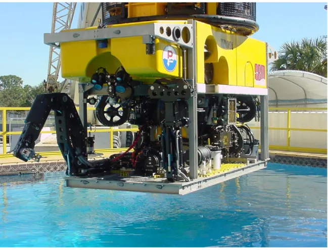
The DSOC was designed to utilize the TRITON ZX Heavy Duty Work Class ROV manufactured by Perry Slingsby Systems. The MNS specified the TRITON ROV. Model ZX was selected because it is the most capable of TRITON ROV’s. Table 7 summarizes the ROV’s characteristics. More detailed information is included as Appendix 0.
Figure 5. TRITON ZX ROV Table 7. TRITON ZX Characteristics
ROV Dimensions 8.1 ft Long x 5.0 ft Wide x 6.2 ft High
Depth Rating 9800 ft
Payload Capacity 441 lb
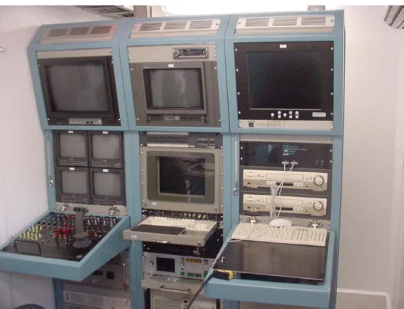
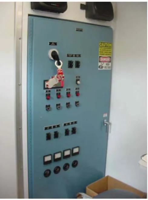
The ROV and its auxiliary equipment are controlled by a set of three consoles in the DSOC. Figure 6 shows a typical arrangement. One console is required for control of the ROV itself and two others are required for control of the auxiliary equipment. Power is provided to the ROV through a high voltage transformer unit (HVTU), a high voltage junction box (HVJB), and a power distribution unit (PDU) (Figure 7 and
Figure 8). Table 8 contains equipment characteristics. All of this equipment is installed on the upper level of the DSOC.
Figure 7. High Voltage Transformer Unit and High Voltage Junction Box
Figure 8. Power Distribution Unit
Table 8. ROV Control Equipment Data
Consoles (Combined) HVTU HVJB PDU
Weight 1300 lb 2300 lb 500 lb 800 lb Height 73.63 in 36.5 in 28.75 in 72 in Depth 26.31 in 21.38 in 24 in 17 in
Width 67.68 in 43 in 36 in 36 in
4.1.3 Lift Mechanism and Equipment
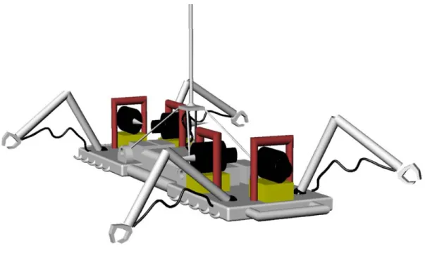
The lift mechanism consists of a maneuverable lift frame, a lift cable, a cable handling system, and associated controls. Figure 9 shows a drawing of the lift frame. For the purposes of this study, the lift mechanism controls and associated equipment are assumed to be identical to those of the ROV.
The cable handling system lowers the lift frame to the object. Once the lift frame is directly above the object, the operator uses manipulator/camera pairs on each corner of the lift frame to attach the frame to the object. The cable handling system lifts the lift
frame and the object into the payload bay. During descent and ascent, the operator controls the horizontal position of the lift frame using thrusters.
Figure 9. Lift Frame
Power and control signals are passed to the lift frame via the lift cable. Table 9 shows the characteristics of a representative heavy lift cable.
Table 9. Characteristics of a Representative Heavy Lift Cable
Theoretical Breaking Load 114,000 lb
Diameter 1.5 in
Weight in Water 2.0 lb/ft Weight out of Water 2.8 lb/ft
4.1.4 Combat Systems/C4ISR
The DSRS contains all combat systems and C4ISR systems of the VIRGINIA Class Submarine.
4.1.5 Propulsion, Electrical and Auxiliary Systems
The VIRGINIA Class Submarine propulsion and electrical generation plants remain unchanged. The ship’s auxiliary systems are modified to:
A. Provide heating, ventilation, and air conditioning to the DSOC. B. Cross-connect to the DSOC hydraulic plant in the event of casualties. C. Cross-connect to the DSOC variable ballast system in the event of
casualties.
D. Connect Ventilation, High Pressure Air and Emergency Main Ballast Tank Systems to the Cargo Bay for Main Ballast Tank functions.
The ship’s electrical distribution system has been modified to provide power to the ROV and lift mechanism controls as well as research and analysis equipment. Table 10 provides a list of the estimated electrical loads on the ships systems. These systems are compatible with 450 V, 60 Hz, 3 phase AC.
Table 10. Estimated DSOC Power Requirements
ROV and Control Equipment 200 kVA Lifting Frame and Control Equipment 200 kVA
DSOC Trim Pumps 50 kVA
Total 450 kVA
4.1.6 Survivability and Signatures
The DSOC utilizes the same hull structure as the VIRGINIA Class Submarine with the exceptions of the apertures for the payload bay and the ROV chamber. The DSRS is expected to have the same level of survivability as the VIRGINIA Class Submarine. More detailed analysis is necessary to verify survivability.
The addition of the DSOC and the scientific and military research missions will affect the stealth of the DSRS in transit and on station. The doors for the payload bay and ROV chamber will affect the stealth of the DSRS in transit by generating additional flow-related noise. The operation of the doors, the ROV, and the lifting mechanism will cause sound transients when on station conducting missions. Further analysis and study is
required to determine the severity of these generated noises and their effects on the ship’s mission.
4.1.7 Manning
The scientific and research functions require four personnel in addition to the ship’s regular complement. Two will be scientists or mission specialists. The other two will be required for ROV and lift mechanism control. The DSOC does not have berthing space, so berthing will be provided in the submarine’s berthing spaces.
Berthing can be obtained by leaving some non-essential personnel ashore for the mission, increased hot racking, or using alternatives such as the Submarine Torpedo Room Berthing Pod (Figure 10), developed by the Dutch company Polymarin. The berthing pod is the size of a MK-48 torpedo and has three berths with individual lighting, forced air ventilation, and storage space. They are loaded onto the submarine and
handled just like a torpedo is handled. The berthing pod is scheduled to be evaluated for use on United States submarines as part of the Office of the Secretary of Defense Foreign Comparative Testing Program.
Figure 10. A Submarine Torpedo Room Berthing Pod being loaded into a Dutch submarine.
4.1.8 Arrangement 4.1.8.1 Stack Length
A previous feasibility study found that the best longitudinal location at which to make a plug insertion is aft of frame 39. The same study used 40-ft plug length, which is insufficient for this modification.15
Equipment stack length drove the compartments 46-ft overall length. The design payload is 23 ft long, 10.5 ft wide, and 6 ft tall. The payload bay requires: 1 ft of object clearance on all sides, 9 in. of space at the fore and aft ends for bay door hydraulic motors and gearing, and 1ft additional side space for the rotating door hinges. This brought the payload bay's overall outer dimensions to 26 ft long and 12 ft wide. Similarly, the bay's 22-ft height was driven by the stacked dimensions of the payload item, lift frame, 3000-ft cable reel, hydraulic motors, and overhead supports (Figure 11).
Figure 11. Payload Bay Internals
The ROV Chamber requires an 11-ft hatch for vehicle egress, as well as 36-in. internal clearances on all sides of the ROV to permit maintenance. As Figure 12 shows, stacked equipment dimensions drove the required height of the chamber.
Figure 12. ROV Chamber Internals
The remaining 4 ft of DSOC length (46 ft, less the 26 ft and 16 ft already allocated) allows sufficient room for personnel to move between the structures on the two lower levels.
4.1.8.2 Reserve Buoyancy
The ship’s safety requires that the Reserve Buoyancy (ROB) be greater than 12.5%. In order to maintain this level of ROB several modifications to the ship’s hull were necessary. The most significant reason for this is the heavy weight of the DSOC. In fact, the DSOC weighs 40% more per foot than the VIRGINIA Class Submarine.
ROB that the ship would have for each plug length with no other modification. The length of the plug was selected as 46 ft to allow for both the ROV Chamber and the Payload Bay. This resulted in a ROB of 11.1%.
10.0% 10.5% 11.0% 11.5% 12.0% 12.5% 13.0% 13.5% 14.0% 20.0 25.0 30.0 35.0 40.0 45.0 50.0 55.0 60.0 65.0 70.0 LPlug (ft) ROB 0 200 400 600 800 1000 1200 1400 1600 Wplug (lton) Required ROB
Add DSOC with No MBT Adjustment Replace Spherical
Array with IBC IBC + Lengthen MBT 4& 5 IBC + Payload Bay MBT + Foam
Actual ROB
WEIGHT
DESIGN
SPACE
IBC + Payload Bay MBT
Figure 13. Plug Length Tradeoff Space
Several options were explored to maintain the required 12.5 % ROB. First, the
existing spherical array was replaced with a conformal array (IBC) to expand the forward ballast tank capacity by 48 lton. This modification raised ROB to 12.1%. Figure 14 shows the variant dimensions after the plug insertion and installation of a bow conformal array.
Figure 14. DSRS Profile
To achieve the required level of ROB, the aft MBT's would require enlargement, or the plug itself would have to incorporate an additional MBT. Calculations showed that lengthening the stern an additional four feet would increase the capacity of MBT 4 and 5 by 92 tons, providing 12.6% ROB. Lengthening the stern would involve significant structural modification to the original VIRGINIA Class design and is contrary to the group’s design philosophy for this project.
Additional calculations showed that the Payload Bay contains 159 lton of seawater. Using the Payload Bay as an MBT and replacing the spherical array with an IBC Array results in a ROB of 13.8%. The longitudinal balance of the ship required reducing the volume of MBT 5. Syntactic foam was added to MBT 5 to achieve the proper
longitudinal balance. The Weights and Stability section provides a more detailed
discussion of the longitudinal balance. After all modifications, the final ROB was 12.8%. 4.1.8.3 Plug Internal Arrangements
In order to minimize impact on the Virginia class, no major alterations were made to the baseline ship arrangement other than the mid-body insertion. DSOC passageway locations correspond to the existing watertight door locations. Some minor changes in
piping, ventilation, and electric cabling runs are required for the modification, but the overall effect on the ship's existing layout is small.
The DSOC is arranged in four levels. Figure 15 shows the upper level. The aft area of the upper level (24 ft ABL) is the Operations Center where ROV and Crane evolutions are monitored and controlled. The forward section of the space is designated as a
"mission flexibility" space. This space is 21 ft long and could be used as a mission stowage space, general stores location, or portable temporary berthing area (though the DSOC contains no sanitary facilities). Figure 15 shows a plan view of the upper level.
Figure 15. DSOC Upper Level
The middle level at 16.5 ft ABL (Figure 16) provides access to the fore/aft tunnel passageway. This level is connected by ladders to the decks above and below. A majority of the space on this level is consumed by the crane bay and ROV Chamber shells, however there remains a significant amount of area for mission related or general stores. This level also houses two dedicated compensation pumps, which can be cross-connected to the ship's trim and drain system.
Figure 16. DSOC Middle Level
The lower level at 7.7 ft ABL (Figure 17) is connected by two ladders to the level above. The space contains the DSOC's 3000 psi external hydraulic plant, ROV Chamber access, and the dedicated EMBT Air Flasks. Eighteen vertically-stored EMBT Air Flasks each hold 7 ft3 at 4500 psi.
Though not analyzed in this design, Figure 17 shows a notional access into the
Figure 17. DSOC Lower Level
The lowest level, is merely a piping and tank space between the lower-level deck and the pressure hull. Payload Bay and ROV pressure hull penetrations occur on this level. Additionally, this deck houses the majority of the compensation tank volume. Figure 18 shows a plan view of the area.
Figure 18. DSOC Tankage Level
4.1.9 Structural Design
The structural feasibility of the PMB concept has been examined in the past. 16It is well known that any departure from a traditional cylindrical pressure hull will most likely require extensive structural reinforcement. The decision to house payload internally drove the requirement for a large, heavy enclosed bay that is part of the pressure hull. Figure 19 shows the resultant pressure hull geometry.
As expected, the DSOC's asymmetric pressure hull results in substantial structural and weight concerns. One concern is the presence of two significant stress concentrators at the bottom of the pressure hull. Conservative structural weight allowances were factored into the initial calculations in anticipation of these concerns. Analyses showed the design to be feasible based upon very conservative structural selections.
All static load safety margins were satisfied, but detailed dynamic calculations are necessary to show that dynamic safety margins are met. Future design iterations will probably show that the DSOC's structural weight can be greatly reduced.
Figure 19. DSOC Cross-Section
4.1.9.1 Main Shell and Framing
The DSOC pressure hull and framing scantlings are based on the current Virginia parallel mid-body design. Reanalysis was considered unnecessary. Use of the existing scantlings also serves to minimize impact on the baseline design and reduce conversion cost.
The payload bay doors introduce a discontinuity into the existing shell form. An elementary moment calculation reveals that bending moment due to hydrostatic pressure at the lower discontinuities will be roughly five times greater than at the top of the
cylinder (Table 11). This result suggests that significant reinforcement will be required at the payload bay doors.
Table 11. Bending Moment Due to Hydrostatic Pressure Location Bending Moment Due to Hydrostatic Pressure
Top Center 1.77 x 10⁸ lb-ft Bay Door Hinge 1.09 x 10⁹ lb-ft
The DSOC design could be vulnerable to UNDEX, shock, and torsion loads.
Although a complete dynamic analysis was beyond the scope of the feasibility study, the group recognized the issue by installing 3 deep frames: at the forward bulkhead (182'), at the aft bulkhead (220'), and just aft of the ROV Chamber (199'). Additionally, when the bay doors are shut they are hydraulically locked and mechanically secured to provide increased sectional rigidity.
Table 12 shows that the overall sectional modulus is only slightly reduced from the baseline model. (These calculations can be found in Appendix A.C.) Consequently, no difficulties are expected to arise from shear and bending.
Table 12. Moments of Inertia about the Neutral Axis Sectional Design Moment of Inertia about Neutral Axis
Baseline Cylinder 2.521 x 104 ft4 DSOC Section 2.433 x 104 ft4
4.1.9.2 Decking and Bulkheads
The DSOC contains three continuous decks supported as shock mounted rafts. For this reason, the decks are not credited as structural reinforcement. The second deck, mounted at 16'4" ABL, is intended to provide only limited longitudinal and lateral
stability for the ROV Lockout Chamber. Additional stiffeners are routed through the third deck that rigidly attach the upper portion of the ROV Chamber to the hull.
Watertight bulkheads enclose the DSOC fore and aft. The aft bulkhead is the existing RC bulkhead from the VIRGINIA Class Submarine design moved 46 ft further aft. The forward bulkhead design is based on a structural model developed in the 2001 design study, The Next Generation Nuclear Attack Submarine.17 The forward bulkhead
incorporates 1.25" HY-80 plating with two 8" transverse beams and seven 3.5" Vertical Stiffeners. Details of this design can be reviewed in Appendix A.C.
4.1.9.3 ROV Chamber
The ROV Chamber is a cylinder 15' 6" in diameter and 22' 6" high with hemispherical upper and lower heads (Figure 20). The chamber was analyzed using an MIT MathCAD Structural Model.18 This model was used to calculate five hull limit states for the
chamber based upon the assumptions that the chamber was a right circular cylinder with a ring-stiffened shell. The shell thickness is 2.00 inches. External 5"-deep ring frames surround the shell at 18" spacing. Table 13 shows the results of the analysis. The
scantling selections provide adequacy for the five failure modes to depths far beyond 800 ft.
This model does not consider the effects of shock or UNDEX. Consequently, the scantling design reflects a great deal of conservatism. Future revisions in the chamber design would likely result in a beneficial weight reduction.
17. Ibid
18. Dave Johnson. “Program to Compute Suitability of Submarine Design Parameters,”
Figure 20. ROV Chamber Scantlings
Table 13. ROV Chamber Failure Mode Stress Ratio Summary Failure Mode σmode/σworking
Lobar Buckling .056 Shell Yield .025 General Instability .219 Frame Yield .033 Frame Instability .476 4.1.9.4 Payload Bay
Due to the unique geometry, the payload bay was the most critical and complex portion of the analysis (Figure 21). The side walls of the bay were modeled as a large
derived in Ship Structural Design that predict the behavior of stiffened panels under hydrostatic load.19
The Payload Bay cap was modeled as a ring stiffened cylinder using Johnson’s MIT MathCAD Structural Model. The final design required HY-80 side and end walls 3 in. thick. Vertical stiffeners 6 in. deep are spaced at 21 in. intervals on the bay ends and at 24 in. intervals on the lateral walls. Transverse frames 8 in. deep are spaced at 4 ft intervals around the circumference of the bay. The bay's shell head uses a 2 in. HY-80 thickness with 3.25 in. ring stiffeners spaced at 14 in. intervals. The 2 in. cylindrical shell plating was selected in order to limit the difference in thickness between the bay wall and the shell head. This set of scantlings also provides structural adequacy to depths well beyond 800 ft.
Table 14. Payload Bay Shell Head Failure Mode Stress Ratio Summary Failure Mode σmode/σworking
Lobar Buckling .020 Shell Yield .026 General Instability .384 Frame Yield .041 Frame Instability .474
19. Owen F. Hughes. Ship Structural Design (Jersey City, New Jersey: The Society of
Table 15. Payload Bay Lateral Wall Failure Mode Stress Ratio Summary
Failure Mode
σ
mode/
σ
workingPanel Serviceability Plate Transverse Bending .750 Panel Serviceability Plate Longitudinal Bending .776 Panel Collapse Membrane Yield .750
Plate Failure Local Buckling .030
Panel Yield Tension Flange .203
Panel Yield Compression Flange .203 Panel Collapse Stiffener Buckling .203 Panel Collapse Stiffener Buckling .804 Panel Collapse Stiffener Buckling 2 (eccentric load) .653
Table 16. Payload Bay End Wall Failure Mode Stress Ratio Summary
Failure Mode
σ
mode/
σ
workingPanel Serviceability Plate Transverse Bending .750 Panel Serviceability Plate Longitudinal Bending .725 Panel Collapse Membrane Yield .741
Plate Failure Local Buckling .023
Panel Yield Tension Flange ..996
Panel Yield Compression Flange .254 Panel Collapse Stiffener Buckling .031 Panel Collapse Stiffener Buckling .798 Panel Collapse Stiffener Buckling 2 (eccentric load) .652
4.1.10 Weights and Stability 4.1.10.1 Baseline Ship Balance
The MIT Submarine MathCAD Model of the balanced VIRGINIA Class Submarine was used in the analysis.20 This model was based upon parametrically derived data. 4.1.10.2 DSOC Balance
The DSOC weight was calculated on an item-by-item basis that required detailed, evolved drawings. Weight estimates for specific pieces of equipment or structure were based on known data from existing platforms. Parametric weight group calculations were used as a second check, but due to its unique function and arrangement, the DSOC was not expected to fall within historical design lanes. In fact, the DSOC weighs
approximately 40% more than predicted by historical parameters.
Vertical and longitudinal locations and moments were also estimated and tracked with assistance of the drawing. The A-1 vertical center of gravity (VCG) is 16.63 ft and the longitudinal center of gravity (LCG) is 18.62 ft aft of the DSOC's forward bulkhead. Table 17 shows the DSOC Weight and Stability characteristics. Detailed weight and moment data is included as Appendix E.
Table 17. DSOC Weight Summary
Weight Condition PLUG Weight (lton) VCG (ft) LCG (ft)
A-1 881.20 16.63 200.62 Lead 25.32 4.00 203.00 A 906.52 16.28 200.69 Variable Load 32.53 12.69 201.71 Variable Ballast 60.00 9.45 217.61 NSC 999.05 15.75 201.74 MBT 159.61 10.70 213.50 SUBMERGED 1158.66 15.15 209.07
4.1.10.3 Modified Ship Balance
The addition of the DSOC plug and its additional Main Ballast Tank (MBT) had a significant impact on the ship's overall longitudinal balance. The section's submerged center of gravity is 16.7 ft aft of the ship's submerged longitudinal center of buoyancy (LCB). MBT modifications were necessary in order to both balance the ship and to preserve the required 12.5% Reserve Buoyancy (ROB).
An Integrated Bow Conformal Array (IBC) sonar was selected to replace the spherical array, since this modification is already planned for future platforms. This allows the forward bulkhead of MBT 1 to be moved forward by 2.9 ft. This alteration, combined with the removal of the sonar sphere access tunnel results in a 48-ton increase in the ship's MBT capacity centered at 19.58 ft aft of the forward perpendicular (FP). The IBC modification was not sufficient to correct the ship's submerged trim condition.
Syntactic foam was inserted into the after-most MBT (formerly MBT 5). The 3643 ft3 (77.8 lton) foam volume permanently displaces 103.8 tons of MBT capacity, bringing the ship's new ROB to 12.8%. Additionally, the foam provides a net buoyancy of 26 lton centered at 374.63 ft. Figure 22 summarizes the modifications. Trim lead and the ship’s variable ballast brought the ship to a final longitudinal balance.
4.1.10.4 Equilibrium Polygon
The group analyzed for worst-case variable load conditions according to standard design practice as specified in NSTM 9290. Since this platform carries a particularly large payload item, two 65-ton DSOC compensation tanks were necessary in order for the ship to conduct retrieval operations in all environments and load conditions, including arctic conditions. Figure 23 shows the Equilibrium Polygon with the addition of payload compensation tanks. In the Heavy 2 condition, the ship maintains a 70-lton margin. The extreme Light Condition remains close to the trim system limits (5-lton margin). It is important to note however, that the Light Condition design water density (64.3 lb/ft3) is
normally encountered at deeper depths, which implies that the Light Condition will migrate downward on the Equilibrium Polygon due to hull and SHT compression. In short, the small Light Condition margin was viewed as an acceptable compromise in preserving the ship’s arctic capabilities. Table 18 shows the seawater densities assumed for the various load conditions. Detailed variable load calculations can be found in Appendix E.
L HA Arctic H2 N HF1 AUX 7 AUX 5/6 AUX 3/4 AUX 1/2 PLUG COMP ATT AUX 1/2 AUX 3/4 AUX 7 AUX 5/6 ATT PLUG COMP 0.00 50.00 100.00 150.00 200.00 250.00 300.00 350.00 400.00 450.00 -15000.00 -10000.00 -5000.00 0.00 5000.00 10000.00 15000.00 20000.00 Moment (ft-Lton)
Variable Ballast (Lton)
Table 18. Seawater Density Assumptions
Condition Density (lb/ft3)
Normal (N) 64.0
Heavy aft (HA) 63.6 Heavy Forward (HF1) 63.6 Heavy Overall (H2) 63.6
Arctic 63.0
Light (L) 64.3
4.1.10.5 Lead Solution
The lead solution requires 209.7 lton of Stability Lead centered at 221.56 Ft and 290.5 lton of Margin Lead centered at 192.06 ft (for an overall total of 500.27 lton centered at 204.43 ft). The modified design increases the baseline ship's overall lead weight by 145.9 lton. This lead addition is offsets the DSOC's excess buoyancy and fine-tunes the longitudinal balance. If the need arose, stability lead could easily be replaced by
permanent weight additions to the DSOC Module. Table 19 summarizes the complete lead solution. Final Ship Weights and Centers of Gravity are shown in Table 20.
Table 19. Lead Solution Summary
Lead Weight (lton) LCG (ft) VCG (ft)
Stability 209.76 221.56 3.00
Margin 290.51 192.06 17.00
Table 20. Ship Weights and Centers Weight (lton) L. Arm (ft) V. Arm (ft) Weight (lton) L. Arm (ft) V. Arm (ft)
Group / Condition Baseline DSRS
100 2778.5 3454.69 200 1348.6 1348.55 300 246.6 268.22 400 167.3 199.05 500 741.8 893.58 600 505.4 504.45 700 260.3 260.35 Condition A-1: 6048.4 182.9 16.2 6903.93 197.88 16.63 Lead: 354.4 158.6 14.2 500.27 204.43 9.90 Condition A: 6402.8 181.5 16.1 7404.20 198.32 16.18 VL 562.2 121.4 13.2 456.97 195.44 11.39 NSC: 6965.1 176.7 15.9 7861.17 198.15 15.98 MBT: 875.8 148 16.8 1009.55 144.63 16.19 Submerged: 7840.8 173.4 16.0 8870.72 192.06 16.00
4.1.10.6 Surfaced Stability During Extreme Load Cases
Trim and stability were analyzed in the surfaced condition in various ballasted and un-ballasted load conditions. The arrangement of the DSOC raises several issues regarding surface stability. On the surface the ship must compensate for the full dry weight of the retrieved payload (56 lton), rather than the waterborn weight of 14.7 ltons. The ship must also compensate for the free surface effect in the mid-ship MBT. The free surface
correction (FSC) due to the additional MBT was calculated to be quite small, 0.01 ft, because the tank is long and narrow in its dimensions. Since the DSOC section is located close to the ship's LCB, extreme load cases in the DSOC plug have very little effect on
the ship's trim. Table 21 and Table 22 show the results of the stability analyses. The ship is stable under all load conditions.
Table 21. Extreme Load Case Stability Parameters Payload (lton) Midship Ballast (lton) Draft (ft) Trim by Stern (ft) GMT (ft)
56 220 (ROV Tank Full) 29.4 7.7 1.80
56 130 29.0 7.0 1.50
56 0 28.4 6.2 1.00
0 0 28.1 5.9 .93
Table 22. Normal Surface Condition Stability Parameters Baseline Variant
(With Payload)
Variant (Without Payload)
Normal
∆
Surf (lton) 6965 8003 7961Mean Draft (ft) 28.18 28.55 28.30
Trim (ft) 5.52 6.40 6.00
KMT (ft) 17.01 17.00 17.00
KG (ft) 15.85 15.86 15.98
GMT (ft) 1.16 1.12 1.05
Roll Period (sec) 11.1 12.3 13.9
4.2 Performance Analysis
The addition of the DSOC will affect the performance of the submarine primarily by making it more stable and slower. The DSRS will be expected to turn slower and have a larger turning radius than the VIRGINIA Class Submarine. The DSRS will also be 11% slower than the VIRGINIA Class Submarine. The speed reduction is based upon the increased friction drag due to more wetted surface area. The complete calculations
regarding speed are contained in the Submarine MathCAD model contained in Appendix B.21
4.3 Operation and Support
The DSRS will require additional support to unload the recovered object at its
destination. This process will be complicated because the only way to unload the object is out the bottom of the ship. This can be performed by having the lift frame lower the object beneath the ship and carefully transfer the load to a crane. This can also be
accomplished by lowering the object onto the sea floor in a safe, shallow area and having a crane lift it directly from the bottom.
The DSRS will also require additional support in the form of parts and technicians to maintain the added equipment.
4.4 Cost
The DSRS estimated to cost $650 Million above the cost of the Baseline VIRGINIA Class Submarine. Cost was estimated using the Very Simplified Cost Model portion of the MIT Submarine Math Model. Table 23 shows the parameters used.
Labor rate is the key parameter is determining the total cost of the ship. However, the DSRS conversion represents only a 20% increase over the cost of the Baseline
VIRGINIA Class Submarine regardless of the labor cost selected (Figure 24). This team looked at labor costs ranging from $50 to $150 per man-hour. The lower rate comes from a study performed in 1991 and does not reflect inflation or other variables such as changes in the labor market. The higher rate comes from a new construction design performed recently and includes significantly more of the expensive new design labor than the DSRS conversion will require.
50 75 100 125 150 15 17.5 20 22.5 25 ($/Man-hour) C onversion C ost 25 15 Percent∆ 150 50 Labor_Rate
Figure 24. Percentage Change in Baseline VIRGINIA Submarine Cost due to DSRS Conversion
Table 23. Cost Estimating Parameters
Labor Rate $50 - $150 per man-hour Overhead Factor 1.5
Profit Rate .11
The cost of the ROV and lift equipment will not be significant in the overall cost of the ship. Table 24 shows the cost of the various portions of the ROV System. The Lift System is expected to cost a similar amount.
Table 24. ROV and Support Equipment Cost
Item Cost
TRITON ZX ROV $775,000
ROV Optional Equipment $250,000 Control Consoles $300,000 Tether Management System $350,000
Power System $60,000
5.0 Design Conclusions
5.1 Summary of Final Concept Design
The Deep Sea Research Submarine final concept design consists of VIRGINIA Class Submarine design modified by the insertion of a 46-ft Deep Sea Operations
Compartment. Table 25 gives the principle characteristics. The DSRS is capable of supporting ROV operations and heavy lift operations in addition to performing all the combat missions of a standard VIRGINIA Class Submarine. The DSRS meets the requirements of the study.
Table 25. Deep Sea Research Submarine and Deep Sea Operations Compartment Characteristics
Deep Sea Research Submarine
Length 423 ft
Diameter 34 ft
Speed Reduction 11%
Surfaced Displacement 7861 lton Submerged Displacement 8870 lton
LCG 192.06 ft
VCG 15.98 ft
GMT 1.05 ft
Reserve Buoyancy 12.8%
Deep Sea Operations Compartment
Length 46 ft
NSC Weight 999.1 lton
Submerged Lifting Capacity 14.7 lton
Maximum ROV Depth 9800 ft
Maximum Retrieval Depth > 2400 ft Conversion Cost $650 million
5.1.1 ROV Operations
The capability to perform ROV operations allows the submarine to perform missions far deeper than warships have been able to go before. These deep-sea missions include:
• Object inspection • Object manipulation • Small object retrieval • Water sample retrieval • Biological observation • Geological sampling.
All of these missions can be performed at depths up to 9800 ft using the TRITON ZX ROV.
5.1.2 Heavy Lift Capability
The ship's heavy lift system permits it to perform missions of interest to both the military and scientific communities. The DSRS’s specific capabilities include:
• Submerged lifting capacity of 14.7 tons from depths greater than 2400 ft • Storage within the submarine’s envelope for retrieved objects up to 23.5 ft
L x 10.5 ft H x 6 ft W
• Remote operation of the lifting frame.
5.2 Final Conversion Design Assessment
This study responds to the need for a multi-mission submarine capable of performing deep-sea scientific and military missions. Based on the results of this study, the design group concludes that the U.S. Navy should expand research and funding in support of the Deep Sea Research Submarine. The group recommends reinforcing relationships with commercial ROV builders and oceanographic research institutions and including experienced deep sea salvors in the design process.
The proposed VIRGINIA modification incorporates very little high-risk technology. The departure from use of the traditional cylindrical hull section represents a design challenge, but the skills and analytical tools exist to overcome these basic engineering
uncertainty, the technology required to successfully carry out the proposed DSRS mission is mature.
5.3 Areas for Further Study
This study examines the deep-sea concept for preliminary feasibility. Many areas still require additional attention. Specific items for further study and analysis, including detailed engineering studies, include:
• In depth structural analysis (including dynamic loading) of the Payload Bay and ROV Chamber, specifically in the region of the hull-bay unions. • Detailed survey of ROV manufacturers to determine existing and future
ROV capabilities as well as the suitability of those ROV’s for the missions of interest.
• Detailed cost model formulation for installation of heavy lift and ROV equipment.
• Survey of deep sea salvage experts to fully assess the current state of technology and the current and projected needs of the salvage community • Comprehensive assessment of ROV maneuvering and control problems
from a submerged platform
• Comprehensive study of precise submarine stationkeeping when operating with an ROV or performing a heavy lift.
• Hydrodynamic and maneuvering analyses of the modified ship • Analysis of flow and transient noise
Acknowledgments
The authors wish to express their appreciation to Mr. J. T. Arcano and Mr. S. F. Burkeen of NAVSEA 05U6. Their guidance and support have made this report possible. Captain R. S. McCord, USN provided invaluable assistance dealing with current issues in deep-sea salvage and diving as well as instruction and guidance for the project. Captain Harry Jackson, USN, RET, provided expert technical advice and the benefit of over fifty years of work in submarine design and construction.
Mr. Peter MacInnes and Mr. Bruce Lokay of Perry Slingsby Systems, Inc. provided assistance regarding ROV’s and associated systems. Mr. Richard Voight of JDR Cable Systems provided information regarding deep-sea heavy lift cables. Mr. Arthur Griffin of Griffin Technical Associates, Inc., provided information regarding the Submarine
References
Burke, David V. “Ship Structural Analysis and Design.” Massachusetts Institute of Technology Class Notes, Cambridge, MA, Spring 2001.
Chairman of the Joint Chiefs of Staff, Joint Vision 2020. Washington, D.C.: US Government Printing Office, 2000.
Department of Defense, Quadrennial Defense Review Report. Washington, D.C.: US Government Printing Office, 2001.
Faltinsen, O.M. Sea Loads on Ships and Offshore Structures. Cambridge, UK: Cambridge University Press, 1990.
Galvin, Mark, Chris Hanson, Joe Harbour and David Hunt. VIRGINIA Class Payload Improvement Concept: Mission Flexibility by Modularity. MIT Conversion Design Project, Cambridge, MA: Massachusetts Institute of Technology, 2000.
Gillmer, Thomas C. and Bruce Johnson. Introduction to Naval Architecture. Annapolis, Maryland: Naval Institute Press, 1982.
Hughes, Owen F. Ship Structural Design. Jersey City, New Jersey: The Society of Naval Architects and Engineers, 1988.
Jackson, Harry A. Jackson, CAPT, USN, Ret. “Submarine Design Trends.” Massachusetts Institute of Technology Professional Summer Class Notes, Cambridge, MA, June 2001.
Johnson, Dave. “Program to Compute Suitability of Submarine Design Parameters.” May 2001.
Lewis, Edward V., ed., Principles of Naval Architecture. Jersey City, New Jersey: The Society of Naval Architects and Marine Engineers, 1988.
Reed, Jeffrey and Mark Walsh. “Massachusetts Institute of Technology XIII-A Submarine Math Model.” July 2001.
United States Navy Fact File: NR-1 Deep Submergence Craft. Updated May 24,
1999. www.chinfo.navy.mil/navpalib/factfile/ships/ship-nr1.html (November 30, 2001) Whitman, Edward C., “Submarines in Network Centric Warfare.” Seapower (July, 1999): 33-36.
A. Mission Need Statement
For
Deep Sea Research Submarine
1. Defense Planning Guidance Element
A. This Mission Need Statement (MNS) provides requirements for a multi-mission submarine with deep-sea research capability for the 21st century battle force vision. Through technology investment and insertion, the Deep Sea Research Submarine (DSRS) will be able to perform deep-sea research missions in addition to all the missions of a fast attack submarine. This submarine must operate wherever required to enable joint
maritime expeditionary force operations, project precise strike power ashore, and conduct scientific and military research missions. The mission capabilities must be fully
interoperable with other naval, interagency, joint and allied forces.
B. This unclassified MNS in part addresses Joint Vision 2020 published in June 2000. This document outlines the vision for creation of a force that “is dominant across the spectrum full spectrum of military operations – persuasive in peace, decisive in war, preeminent in any form of conflict”. Additionally, the document addresses “the need to prepare now for an uncertain future”.[22]
C. The deep sea research functions described in this MNS address the requirements set forth in Joint Vision 2020 to have “access to and freedom to operate in all
domains”[23] as well as support the information superiority that has been regarded as a key enabler of victory.[24]
D. This MNS should guide 21st century DSRS design, research, development and acquisition program decisions, service and joint doctrine, and cooperative efforts with U.S. allies.
22. Chairman of the Joint Chiefs of Staff, Joint Vision 2020 (Washington, D.C.: US
Government Printing Office, 2000). 1
23. Ibid., 8 24. Ibid., 10