Design and Analysis of a
Non-Pressurized Manned Submersible
ARCHIVES
A R~$CHt)rVESA UT by rS IT T TUTE OF TECHNOLOr :yv Paul Holzer B.S. Mechanical Engineering University of Florida, 2003 8
SUBMITTED TO THE DEPARTMENT OF MECHANICAL ENGINEERING IN PARTIAL FULFILLMENT OF THE REQUIREMENTS FOR THE DEGREE OF
MASTER OF SCIENCE IN NAVAL ARCHITECTURE AND MARINE ENGINEERING
AT THE
MASSACHUSETTS INSTITUTE OF TECHNOLOGY JUNE 2011
© 2011 Paul W. Holzer, All Rights Reserved
@ 2011 The Charles Stark Draper Laboratory, Inc., 2011, All Rights Reserved The author hereby grants to MIT and Draper permission to reproduce and to distribute publicly copies and electronic copies of this thesis document in whole or in part,
in any medium now known or hereafter ed.
Signature of A uthor: ... . .
epartment of Mechanic Engineering
May 6, 2011
C e rtified by : ...
John J. Leonard, Ph.D. Professor of Mechanical Engin/ering and Oqean Fngineering
C e rtified by : ... ..
Mark S. Welsh Professor of the Practice of Naval ConstructioTpandjnjneering D raper A dviso r: ... ....
Pary
arles ory
A cce pted by : ...
David E. Hardt, Ph.D. Professor of Mechanical Engineering Chairman, Department Committee on Graduate Studies
Design and Analysis of a
Non-Pressurized Manned Submersible
by
Paul Holzer
Submitted to the Department of Mechanical Engineering
on May 6th, 2011, in partial fulfillment of the requirements for the degree of Master of Science in Naval Architecture and Marine Engineering
Abstract
Non-Pressurized Manned Submersibles (NPMS) have proven their utility in warfare for centuries, demonstrating an unmatched combination of simplicity and versatility in both declared conflicts and undeclared, covert operations. Today, the SEAL Delivery Vehicle (SDV) Mk8 Mod1 remains the United States military's most reliable and clandestine method for deploying special operations forces (SOF) to and from the maritime environment. However, the undersea missions of tomorrow are of increased duration, difficulty, and complexity. In their existing configurations, many current NPMS are unable to meet these growing demands, and leaders are forced to seek alternatives which close the gap between current capabilities and future requirements. This thesis is strictly an academic effort intended to demonstrate that through deliberate, cost-effective modifications and a systematic reorganization within their existing hull form, NPMS of today can meet the mission criteria of tomorrow. Moreover, performance objectives such as increased payload, combat radius, and enhanced mission scope can not only be achieved, but in a timely manner and at a reasonable price. To best illustrate the effectiveness of this approach, this document follows the methodology and final results of a thirteen month "optimization" study of the SDV Mk8 Mod1, and will offer a comprehensive analysis and comparison of non-dimensional design parameters between the final product and her predecessor.
Thesis Supervisor: John Leonard, Ph.D., MIT Mechanical Engineering Title: Professor of Mechanical Engineering and Ocean Engineering Thesis Reader: Mark S. Welsh
Title: Professor of the Practice of Naval Construction and Engineering
Acknowledgements
This document is the result of countless hours and collaborative efforts by many individuals and institutions. Foremost, recognition should be given to the spirit and often unnoticed sacrifices of the undersea warriors of the past, present, and to come. I am grateful to both the Massachusetts Institute of Technology and the Charles Stark Draper Laboratory for providing the opportunity to earn an exceptional education and fulfill a lifelong goal.
Sincere gratitude is extended to the following people and groups for their efforts throughout this project, from the initial "napkin" conceptual sketches to the final design:
Senior Chief Paul A. Robinson and the Operators of ALFA Platoon, SEAL Delivery Vehicle Team One, Hawaii
Mr. Joel Parry, Mr. Glenn Ogrodnik, and the members of the SDV Optimization Study at the Charles Stark Draper Laboratory
Dr. John Leonard, Ph.D., and Mark Welsh, Captain USN, Professors, Department of Mechanical Engineering, Massachusetts Institute of Technology
Mr. John Green and the Naval Special Warfare Command
Mr. Pat Broderick and Mr. David Fonzi, NSA Panama City, Florida
Finally, it was my sincere privilege to collaborate with Ken Shepard during this project. Without his truly brilliant work and common-sense approach, this success would not have been possible; my most genuine thanks.
Table of Contents
Abstract ... 3 Acknowledgem ents... 5 Figure Index ... 9 1. Introduction... 10 1.1 Background ... 10 1.2 Description ... 101.3 Lim itations and Constraints... 11
2. Project Goals and Requirem ents... 12
2.1 Design Philosophy - "Do No Harm "... 12
2.2 Design Scope ... 12 2.3 Design Approach... 14 3. Mechanical Subsystem s ... 19 3.1 Hull Subsystem ... 20 3.1.1 Buoyancy PODs ... 20 3.2 Air Subsystem ... 22
3.3 Ballast and Trim (B&T) Subsystem ... 22
3.4 Control, M ast, and Drain Subsystem s... 25
3.5 Propulsion Subsystem ... 25
3.6 Battery Subsystem ... 25
4. Electronic Subsystem s ... 27
4.1 Navigation Subsystem ... 27
4.2 Power and Signal Distribution Subsystem ... 27
4.3 Control/Display Subsystem ... 27
4.4 Docking Sonar Subsystem ... 27
4.5 Obstacle Avoidance Sonar Subsystem ... 27
4.6 Com m unications Subsystem ... 28
4.7 Recording Subsystem (SOM SC)... 28
5. Naval Architecture Assessm ent and Stability Analysis... 29
5.1 Assum ptions and Fundam entals... 29
5.2 Subm erged Stability... 33 Page 7 of 70
5.3 Surface Stability... 33
5.3.1 Approach ... 34
5.3.2 Stability Param eters... 37
5.3.3 Curves of Form ... 42
5.3.4 Surface Stability Conclusions... 43
5.4 Equilibrium Polygon and M ission Loading Conditions... 44
5.5 Hydrodynam ic Effects ... 46
5.5.1 Friction Drag... 46
5.5.2 Form Drag... 48
5.5.3 Hydrodynam ic Conclusions... 52
5.6 Prototype Developm ent and Testing ... 53
5.6.1 Purpose... 53
5.6.2 Initial Construction... 53
5.6.3 Concept Testing - Massachusetts Institute of Technology - SEP 2010... 54
5.6.4 Operational Testing - Panama City Florida - DEC 20 10 ... 54
6. Conclusion ... 56
6.1 Sum m ary ... 56
6.2 Future Recom m endations ... 56
6.3 Bibliography... 57
APPENDIX A... Sum m ary of Design Param eters ... 59
APPENDIX B ... Equilibrium Polygons and Loading Configurations ... 62
APPENDIX C ... Hydrostatic Curves of Form ... 68
Figure Index
Figure 1 - D esign Spiral ... 14
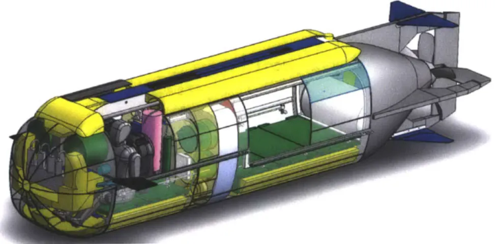
Figure 2 - The Proposed Non-Pressurized Manned Submersible (NPMS)... 16
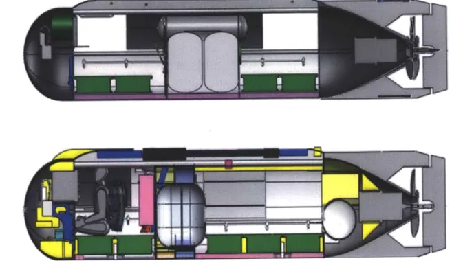
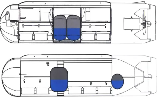
Figure 3 - Comparison of Usable Crew Space (SDV, Top) (NPMS, Bottom) ... 17
Figure 4 - Comparison of Internal Arrangements - (SDV, Top) (NPMS, Bottom) ... 18
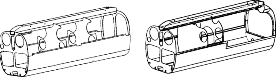
Figure 5 - Hull and Structural Arrangements -Mk8 Mod1 VS NPMS... 20
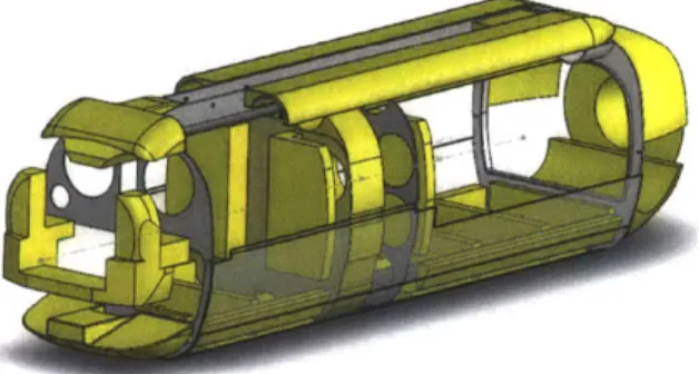
Figure 6 - Location of Buoyancy PODs in Proposed Design... 22
Figure 7 - CBT Locations - Current (Top) Versus Proposed (Bottom) ... 23
Figure 8 - Proposed FBT ... 23
Figure 9 - Proposed ABT... 24
Figure 10 - Conceptual "Toroidal" ABT ... 24
Figure 11 - Proposed O BT ... 25
Figure 12 -Axial Convention for Analysis... 30
Figure 13 -Archimedes' Principle - Force Balance in the Z-direction... 30
Figure 14 -Transverse Stability (Submerged and Surfaced) ... 31
Figure 15 - Longitudinal Stability... 32
Figure 16 - Contributing Internal Pieces... 34
Figure 17 - One of the Numerous, Incremental "Slices" (Mid-Z Axis)... 35
Figure 18 - Draft versus Displacement (Non-Dimensional) ... 36
Figure 19 - Proposed NPMS, Surfaced at DWL... 36
Figure 20 - NPMS Cross and Planar Section... 42
Figure 21 - Locations of K, B, G, and M (Surfaced)... 43
Figure 22 - Righting Arm Curve for the Surfaced NPMS ... 44
Figure 23 - Equilibrium Polygon for Extreme Environmental and Loading Conditions45 Figure 24 - Ideal Hydrodynamic Shape Versus Mk8 Mod1 ... 46
Figure 25 -Boundary Layer Diagram ... 47
Figure 26 - Form Drag - Broad Versus Narrow Pressure Wakes ... 48
Figure 27 -Varying Form Drag Coefficients for Various Geometries ... 49
Figure 28 -The SDV is a Bluff Body, Form Drag Predominates ... 49
Figure 29 -Drag Coefficients and Reynolds Number versus Speed... 51
Figure 30 -Wetted Surface Area Comparison (SDV vs. NPMS)... 52
Figure 31 -Prototype Construction and Completion, MIT, September 2010 ... 53
Figure 32 -Proof of Concept - Six Divers in Aft Compartment (MIT)... 54
Figure 33 -Proof of Concept - Six Divers in Aft Compartment (Panama City) ... 55
1. Introduction
1.1 Background
The SDV Mk8 Mod1 represents years of advances and adaptations in undersea special operations. The concept of employing submerged combatants for the purposes of executing highly specialized tasks has proven its utility in modern warfare. Examples can be traced back to the American Revolution, the Civil War, and World Wars I & II, as well as current operations. The use of a non-pressurized, fully "flooded" submersible offers both simplicity and versatility in its application, often at a significant reduction in cost and number of personnel required than its pressurized counterpart.
1.2 Description
The SDV is a combat system of the United States Naval Special Warfare Command designed to carry combatant swimmers (typically SEALs) and their required mission payloads to and from a prescribed target, submerged and undetected. The craft is fully flooded leaving the passengers within exposed to ambient water temperatures and pressures, and when underway, reliant on various underwater breathing apparatuses (UBAs). A minimum crew consists of a pilot and navigator seated in the forward section. Depending on the specific mission undertaken, the current SDV may carry up to four mission specialists in the rear compartment for a total of six operators at any one time. An SDV and crew may perform missions of a completely subsea nature (such as a harbor penetration) or act as a clandestine vehicle for launching SEALs within range of a beachhead for missions across the hinterland (OTB). The SDV may be launched or recovered from a variety of platforms, including surface ships, submarines, or pier side, and can be transported by land, air, or sea. It employs silver zinc rechargeable batteries and an electric motor for propulsion, and typically cruises at about 20 feet below the surface of the water. The SDV is highly regarded for both its versatility and overall performance across many categories.
1.3 Limitations and Constraints
The undersea special operations of tomorrow demand a platform with increased submerged duration, combat radius, power capacity, advanced technological systems, and the ability to put more combatants on target. The SDV Mk8 Mod1 does not accomplish this. The question then becomes a matter of how best can these specific mission requirements be achieved? At first there seem to be many possible choices, of which the design of a newer, larger craft that incorporates all these needs seems to be the natural pick. Unfortunately, this solution comes with complications all its own. First, those familiar with the SDV know that usable space is always at a premium, but the desire to build "outward" is primarily handicapped by the dimensions of the SDV's principle launch platform, a submarine configured Dry Deck Shelter (DDS). Without modification to the DDS, it would be nearly impossible to attain these improvements in the few inches of remaining space. This course of action, however, is highly unlikely. Next, on top of the sheer complexity of modifying the DDS, budgetary constraints present a significant hurdle. One could hypothesize that to build an SDV would cost millions of dollars, but altering one single DDS would surely cost magnitudes higher. Lastly, any change to the very conduit that links a submerged nuclear submarine with the outside ocean is a very precarious undertaking, requiring numerous certifications and thorough engineering analysis.
Thus, the limitations of the current DDS combined with the typical detractors of new system development, i.e. higher cost, lengthy timeline, numerous testing, and extensive retraining (to name a few), causes another, more appealing solution to emerge from the field of alternatives.
The purpose of this thesis is two-fold. First, describe the methods and decisions required to design a non-pressurized manned submersible (NPMS) that addresses these new requirements. Second, present the final design and demonstrate its capability to the fleet. Chapter Two focuses on the design process and the overall evolution of the NPMS. Chapters Three and Four divide her into two main categories, outlining individual mechanical and electrical systems, followed by specific proposed modifications. Chapter Five subsequently applies a fundamental naval architectural analysis to the NPMS design and examines surface stability, submerged stability, and hydrodynamic effects. In the latter half, Chapter Five then describes how the design was taken from the drawing board and built into a full scale mock-up, in order to
effectively demonstrate the design's feasibility. Lastly, Chapter Six summarizes the whole effort and provides specific reasons why this approach not only makes sense, but is a preferable solution.
2. Project Goals and Requirements
2.1 Design Philosophy - "Do No Harm"
It is unlikely that the current configurations of the SDV Mk8 Mod-1 will be able to meet new mission requirements, such as increased submerged duration, combat radius, and power capacity. However, operators, past and present, have long felt that the existing SDV platform can be modified to meet these challenges. Many of the ideas within this report reflect years of input from SDV operators, experts, and technicians as to how such a modification would be accomplished.
Before delving into the scope and approach of the proposed NPMS, it is important to enumerate the specific principles that guided critical design decisions. They are as followed:
1. Do no harm - every change to the craft should only improve or maintain capability, not degrade, diminish, or eliminate current performance
2. Regard the needs of the operator as paramount, remember lessons learned from the past, and continually seek input from the end user
3. Modifications should accomplish numerous objectives, minimize cost and have "the most bang for the buck"
4. Recommendations should emphasize simplicity and provide solutions for near term implementation
5. The final design should minimize impact to existing host platforms, personnel, and other ancillary systems
6. Cooperation and compliance with on-going or future re-design efforts should be integrated whenever possible
2.2 Design Scope
It was paramount to early on define the scope of this project and identify specific capability improvements from the numerous systems within the SDV Mk8 Mod1 which would benefit from analysis and upgrade. Tackling all or most of them in a single effort would quickly exceed the budget and timeline of this project. Therefore, it
became our goal to get an "initial win" that could be expanded upon later and would be synergistic with on-going efforts.
Thus, potential improvements were separated into three distinct areas: 1) Electronic Systems Upgrades
2) Propulsion System Design and Upgrade 3) Hull and Structural Modifications
At the beginning of the project there were already numerous initiatives underway addressing the electronic systems, and propulsion upgrades alone would not address how to put more combatants on target. However, the third option, hull and structural modifications, accomplished the largest number performance goals with the smallest expenditure of cost and time. Thus, it was decided that this project would focus solely on offering creative solutions within the existing structure.
Once this approach was confirmed, the overall task was divided into specific performance categories by which at the end of the project it would be possible to clearly measure the effectiveness of the end design. These subcategories include:
1) Passenger and Crew 2) Cargo Payload
3) Minimum Water Depth 4) Combat Radius 5) DDS Interoperability 6) NET Ready 7) Survivability/Threat Detection 8) Signature 9) Life Support 10) Navigation Accuracy 11) Tactical Transportability 12) Ballast System 13) Water Temperature 14) Maximum Water Depth 15) Administrative Transport 16) Cruise/Max Speed Submerged
2.3 Design Approach
During the course of the project, the evolution of our design closely mirrored the "design spiral" as illustrated in Figure 1 (Mark Welsh, 2010):
Owner Requirements_ Payload
(cargo, mission systems) Hull Geometry
(form and size)
5-Space and angements Weights and Centersj n" 2 3
Cost R&D, Construction, and Operations and Support
Survivability Seakeeping Manning Propulsion Plant I M&E FreeboardStability and Trim (intact, damaged)
Figure 1 - Design Spiral
The following discussion will address these individual design considerations in detail. 1) OWNER'S REQUIREMENTS:
Of the many (presumed) "owner" requirements, we chose to accomplish the following goals through modification and internal reorganization within the existing hull:
1. ADD ADDITIONAL OPERATORS
In order to put more operators on target, our goal was to modify the aft compartment allowing for the inclusion of two additional mission specialists. During future missions requiring six mission specialists, it is assumed that they would utilize the smaller, closed-circuit, Mk-25 Draeger UBA. If the larger Mk- 16s UBAs were required, the design would only accommodate four personnel. Both configurations, however, would offer an identical level of comfort, or "packing density," that operators experience in the SDV today.
2. INCREASE PAYLOAD CAPACITY
To address the need for larger payloads, we sought to design a craft that could accommodate significant negative, "wet" weight while underway. However, the ability to strictly carry such a payload is not enough, as often the SDV will be tasked to drop
9
P
off or retrieve items and must be designed to accommodate the drastic shift in buoyancy following the loss of this load. This phenomenon would be experienced in over-the-beach (OTB) missions as well as subsea device emplacement; the ability to both carry and compensate for the new load is essential. Our goal was an increase in payload of at least 80 percent over the current SDV.
3. INCREASE "ON-DEMAND" BUOYANT LIFT
In an emergency, any NPMS must have the ability to surface (and remain there) until conditions are resolved. Our design sought to include a more robust, conformable Open Ballast Tank, which would provide additional "on-demand" surfacing capability of more than 40 percent over the current system in the SDV.
4. INCREASE BATTERY CAPACITY
NPMS operations are a delicate balance between diver physiology, environmental conditions, and power consumption. Operating at deeper depths offers improved stealth, but introduces colder temperatures and reduced submergence times. Likewise faster cruise speeds decrease overall transit times, but may increase signature and deplete power stores. Recent use of energy "hungry" technology causes battery capacity to be a principal limitation; thus we included an additional identical battery box in the aft compartment, which provides mission planners with an extra 25% battery capacity over the Mk8 Mod1. While specific combat radius and mission duration values are classified, it is not hard to imagine how additional power would be quite advantageous.
2) PAYLOAD:
Next, the design was tailored to the execution of specific types of missions, and incorporation of their respective payloads. Depending on the individual NPMS in question, many of the operations listed may not be possible. Our optimized NPMS design sought to include the following:
- 6 man, 24-hour Over-The-Beach Mission (OTB) - 6 man, Combat Swimmer Mission
- Combat Swimmer with Diver Propulsion Device
- Heavy Payload, Deep Profile, Bottom Out - Multiple Payload, Deep Profile
3) HULL GEOMETRY:
As previously stated, changes to the external hull were disadvantageous in terms of cost, time, and future integration; significant alterations to the exterior of the craft were avoided.
4 & 5) SPACE and ARRANGEMENTS/WEIGHTS and CENTERS:
Continuing with the design spiral, the next two steps were closely interconnected. Internal arrangements and accurate record keeping would be very complex. The three dimensional computer model became ideally suited and an indispensable tool, allowing for instant and quantitative "trial by error" problem solving. It cannot be overstated how useful this tool was during the design and subsequent analysis.
The next items of the design spiral, from freeboard and trim to stability and sea keeping, constitute most of the subsequent discussion of this report and will be
discussed in detail later.
Several iterations of the spiral ensued as feedback was received from program managers, engineers, and operators. Issues such as diver safety, payload size, door accessibility, future operations, and emergency procedures were raised and addressed over a period of several months.
Lastly, once the design was near completion, an independent cost analysis was performed, providing potential end users with a budget, timeline, and proposed method to implement the suggested modifications. If these values were deemed acceptable, this would constitute the single, largest advantage to the optimization design approach over new system development.
After several months, we arrived at an acceptable design that met our stated intent. Below are illustrations of the proposed, optimized NPMS:
Figure 2 - The Proposed Non-Pressurized Manned Submersible (NPMS)
Appendix A compares key design features of the NPMS with its predecessor and highlights the achievement of our initial project objectives from the previous section.
Additionally, two other categories reflect potential improvements:
* A newer-model Doppler-velocity log (DVL), obtained from the original vendor (Teledyne), may offer improved navigational accuracy; only in water testing will validate this assumption. (Teledyne, 2011)
e An additional foam configuration, outfitted with H- 100, could allow for
operations requiring increased payload, but in greater water depths than the H-80 configuration. (DIAB, 2010)
The most valuable result is the increase in "usable" volume; that is, any space where personnel or gear can be stowed and accessed while underway. Through efficient internal arrangement, the optimized NPMS boasts 30% additional space, as illustrated in Figure 3 and Figure 4
Figure 3 - Comparison of Usable Crew Space (SDV, Top) (NPMS, Bottom)
3. Mechanical Subsystems
The existing SDV is a combination of several systems, some of which would be impacted by an internal redesign or configuration, as outlined in Table 1. These
components are critical and will be discussed individually in the sections that follow.
Hull Mid-body/Frame Modify
Bow None
After-section None
Canopies Redesign
Top-skins Redesign
Buoyancy Pods Redesign
Air Air flasks Redesign
Hoses Modify
Valves/ Fittings/X-ducer None
Mounting Brackets Redesign
Ballast& Trim Close Ballast Tanks Redesign
Open Ballast Tank Redesign
Valves/Fittings/Relief Valve None
Hoses Modify
Control Control Stick None
Torque Tube None
Bow/Rudder/Stern Planes None
Cables Modify
Mast Mast None
Air Cylinders Redesign
Brackets Modify
Hoses and Fittings Modify
Drain Drain Cylinder, valves, fittings None
Drain Plate, Bracket None
Hoses None
Propulsion Motor/Controller Assembly None
Propeller None
Battery Battery Box/Lid None (Additional box)
Battery Tray None
Internal Hardware None
U/W Cables Modify
Table 1 - Required Modifications by Subsystem
3.1 Hull Subsystem
The hull subsystem consists of an aluminum mid-body that is covered with fiberglass and aluminum skins, a fiberglass after-body, and an ABS bow. The hull defines the personnel and cargo compartments and provides a structural surface for the attachment of components and assemblies that make up the other subsystems. Built into the hull subsystem are buoyancy pods that provide fixed buoyancy. The hull subsystem also allows for a lifting sling as a means to launch and recover the SDV with a hoist or crane. The original hull subsystem and proposed configuration are juxtaposed below in Figure 5:
Figure 5 - Hull and Structural Arrangements -Mk8 Mod1 VS NPMS
As a result of the internal hull modifications, the usable space in aft cargo area was increased by more than 30%. This effort included relocating the ALSS air flasks, ballast tanks, bulkheads numbers 2, 3 and 4, and electronic canisters. Physical modifications were performed to the bottom skins (to allow for larger payloads), top skins, canopies, doors, and buoyancy pods.
3.1.1 Buoyancy PODs
A traditional submarine, because of its enclosed envelope and significant displacement, experiences a buoyant force greater than its total weight, and thus is inherently buoyant and floats when on the surface. In order to submerge, the vessel must overcome this imbalance; designers employ a combination of lead weights and a variable "ballast" system to allow the vessel to submerge on demand.
With the SDV MK8 Mod1, however, the experience is quite different. Due to its many free-flooded spaces, its displacement is less than its total weight and is inherently negative. Without the numerous buoyant inserts, referred to as PODs, the craft would sink. The SDV requires these PODs distributed internally in such a manner that when on the surface, it will remain both afloat and upright.
As upgrades and installation of commercial technologies were incorporated into the SDV over time, additional PODs were required to offset the additional weight. Unfortunately, while necessary, these supplements would often encroach on the limited operational space. After several iterations of this ad-hoc approach, the SDV is effectively "out of room" and would benefit from a focused overhaul to relocate or combine the existing PODs, described below.
A buoyancy POD is comprised of a Divinycell foam core, coated with a protective layer of fiberglass and resilient paint. It is molded and shaped to form and can be outfitted with fasteners or threads to aid in installation. In the current SDV, Divinycell grade H-80 is the standard, but the optimized design will employ either H-H-80 or H-100, depending on specific mission requirements. Specific properties for the Divinycell foam (DIAB, 2010) are provided below in Table 2.
Technical Data for Divinycell H Grade
IN. 11 N. 11...
y1) IS845 kg/rn3 38 48 60 80 100 130 160 200 250
Nominal Density lb/ft3 2.4 3.0 3.8 5.0 6.3 8.1 10.0 12.5 15.6
Compressive ASTM D MPa 0.45 0.6 0.9 1.4 2.0 3.0 3.4 '4.8 6.2
Strength 2 AM 1 psi 65 87 130 203 290 435 493 696 899
Compressive ASIM D1621 MPa 40 50 70 90 135 170 200 240 300
Modulus psi 5,800 7,250 10,150 13,050 19,575 24,650 29,000 34,800 43,500
MPa 1.0 1.4 1.8 2.5 3.5 4.8 5.4 7.1 9.2 Tensile Strength ) ASTM 0 1623 psi 145 203 261 363 508 696 783 1,030 1,334
MPa 49 55 75 95 130 175 205 250 320
Tensile Modulus 2 ASTM D 1623 psi 7,105 7,975 10,875 13,775 18,850 25,375 29,730 36,250 46,400
MPa 0.4 0.56 0.76 1.15 1.6 2.2 2.6 3.5 4.5
Shear Strength ASTM C 273 psi 58 81 110 167 232 319 377 508 653
MPa 12 15 20 27 35 50 73 85 104
Shear Modulus ASTM C 273 psi 1,740 2,175 2,900 3,915 5,075 7,250 10,590 12,325 15,080
Shear Strain ASTM C 273 % 9 12 20 30 40 40 40 40 40
1) Typical density variation ± 10%.
2) Perpendicular to the plane. All values measured at +23*C (73.40F).
Table 2 - Divinycell Technical Data (H-80 and H-100)
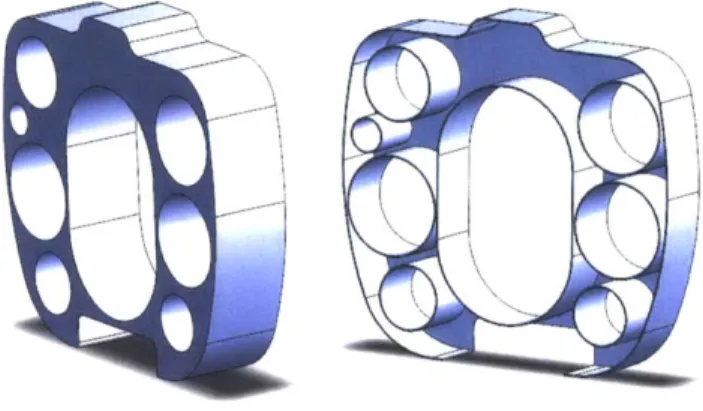
The proposed design, with the ability to carry greater payloads and an additional battery box, required several additional buoyancy inserts. Combined, the PODs constitute nearly 50% more volume than in the current SDV, but their effective and creative placement, seen in Figure 6, provides 30% additional room to the crew.
Page 21 of 70
Figure 6 - Location of Buoyancy PODs in Proposed Design
3.2 Air Subsystem
The current SDV air subsystem consists of two high pressure composite air flasks, a manifold, several valves, fittings, hoses, and a pressure transducer. The new system will replace the existing air flask with two new composite air flasks of a similar design. The new air flasks will be located above the aft compartment and run parallel to the strong-back. The redesigned air flasks will have the same pressure and volume ratings as the existing system. This new air system provides two additional valve stations to support diver quality air. The hoses must be modified and the manifold, valves, and pressure transducer will have to be relocated.
3.3 Ballast and Trim (B&T) Subsystem
The Ballast and Trim (B&T) subsystem allows the SDV to submerge, achieve neutral buoyancy, and maintain a desired attitude under varying load conditions. It is a closed pneumatic system which utilizes high pressure air to move water between two closed, rigid ballast tanks (CBTs), one forward of amidships (FBT) and one aft of amidships (ABT). The new B&T subsystem design focused on increasing both the capacity of the CBTs and their respective moment-arms. This was accomplished by designing new, larger CBTs and increasing their respective distances from the center of gravity (CG). The B&T system retains most of the existing hardware used in the baseline SDV.
Figure 7 - CBT Locations - Current (Top) Versus Proposed (Bottom)
The FBT is constructed of the same 5086 H 116 aluminum alloy as the original tank, but increased in size. The width of the tank was constrained by the electronic canisters now located on both sides of the tank. The length was minimized to allow the most room for the crew in the adjacent compartments. As can be seen in Figure 8, the
FBT is no longer a simple cylinder (Shepard, 2011):
Figure 8 - Proposed FBT
Likewise, the ABT is constructed of the same 5086 H 116 aluminum alloy. It is larger than its predecessor, but smaller than the proposed FBT. The ABT sits low in the vehicle, aft of bulkhead four where an amplifier canister was previously located. The new position provides clearance for overhead gear and allows for adequate fluid flow
over the electric motor. The "standard" shape, seen in Figure 9 (Shepard, 2011), was intended to minimize cost when acquiring it from a vendor. Efforts are currently in progress to find a tank form that both uses the open space around the motor canister and allows for adequate cooling (Figure 10), thus providing even more "usable" space to the crew.
Figure 9 - Proposed ABT
Figure 10 - Conceptual "Toroidal" ABT
The subsystem also provides a means for rapid surfacing by displacing water from an Open Ballast Tank (OBT). This tank is open on the bottom and is flooded during submerged operations; when needed, operators can force high pressure air into the space, forcing water out and creating a buoyant "lift" force on demand. This serves primarily as a safety feature. When fully activated, it causes several inches of the SDV
strong back to remain out of the water creating a stable, usable platform.
The current OBT is located between the CBTs, and is formed by a welded shroud over their exteriors. In the proposed design, the overall capacity of the OBT was increased, while its location moved slightly forward, allowing for an additional battery box. The proposed OBT (Figure 11) would be fabricated from a composite material for ease of
manufacturing,
2011).
weight constraints, and improved corrosion resistance (Shepard,
Figure 11 -Proposed OBT
The majority of the ballast system will remain unchanged and use the same parts and components as the original, with a few exceptions. First, the two liquid level indicators will need to be replaced due to change in the probe length. Second, minor software modifications to the control and display subsystem may be required to account for the new tank capacities. Lastly, some hose assemblies must be modified to account for the relocation of the tanks.
3.4 Control, Mast, and Drain Subsystems
Minimal changes to these systems are required. Relocation of the mast cylinder and various cables comprise the bulk of the effort required to integrate these three subsystems.
3.5 Propulsion Subsystem
In an effort to reduce overall cost and risk to the program, the proposed design will utilize the same motor-controller assembly and propeller as the existing SDV. Since the hull form, wetted surface area, and drag of the new design is comparable to that of the current SDV (see section 5.5 Hydrodynamic Effects), the current subsystem, including control surfaces, may be reused.
3.6 Battery Subsystem
The current SDV Battery system consists of four battery housings, interconnecting cables, battery trays and individual battery cells. The proposed design will incorporate
an addition battery housing, or "box," located in the aft compartment. The increased battery capacity will offer improved combat radius, maximum speed, and additional power capacity for new electronic systems.
4. Electronic Subsystems
As stated earlier, this study intentionally did not incorporate any modifications or technical upgrades to the electronic subsystems in an effort to reduce overall cost and risk to the program. However, various electronic components were relocated and are discussed in the following section.
4.1 Navigation Subsystem
The current SDV navigation subsystem namely consists of a Doppler velocity log (DVL), GPS, compass, and sound velocity sensor. The components will be utilized in the new design but will require a smaller, equally capable, DVL (Teledyne, 2011) and re-routing of the various associated cables.
4.2 Power and Signal Distribution Subsystem
The current power and signal distribution subsystem consists of the 1553 bus unit, power distribution unit, tracking light and associated underwater cables. The proposed design will utilize the same subsystem as the original but will require relocating various components and cables.
4.3 Control/Display Subsystem
The current control and display subsystem consists of the two display units, mouse assembly, and associated underwater cables. Only software modifications to the operating system are anticipated.
4.4 Docking Sonar Subsystem
The current docking sonar subsystem consists of the docking sonar interrogator unit and Hydroid transponder. Identical components will be used, but minor relocation of some components and cables may be required.
4.5 Obstacle Avoidance Sonar Subsystem
The current obstacle avoidance subsystem consists of a commercial sound head, processor electronics, and associated underwater cables. While our proposed design has minor impact to this system, efforts to upgrade or replace this system, already in progress, will undoubtedly affect this subsystem in the future.
4.6 Communications Subsystem
The current communications subsystem will not be affected.
4.7 Recording Subsystem (SOMSC)
The current Recording Subsystem consists of the On-Board Mission Support Computer (SOMSC), Plug-n-Play Unit, and associated underwater cables. Similar to the OAS subsystem, efforts to upgrade or replace this system, already in progress, will undoubtedly have an effect this subsystem in the future and should be considered.
5.
Naval Architecture Assessment and Stability Analysis
5.1 Assumptions and Fundamentals
In this section, the proposed NPMS will be analyzed for its application at sea, both on the surface and submerged, in varying environments, and under specific mission loading requirements. Topics of discussion will include: determination of critical parametric values, development and examination of the Curves of Form, a cursory hydrodynamic analysis focusing on form and viscous drag forces, and the development and testing of a full scale prototype used to illustrate the "proof of concept."
Consistent with this entire document, classification and security concerns have been mitigated through the use of "non-dimensional" values; proposed design parameters are presented as fractions of "baseline" values from the SDV Mk8 Mod 1.
Throughout the course of this analysis, several initial assumptions were necessary. First, the sea state in which the vessel will be operating is assumed to be sufficiently calm and void of any extreme currents, exempt from any conditions that would exceed those required for the safety of the crew. Unless otherwise stated, the vessel is in its light or "slick" configuration which includes the standard electronic and propulsion components, two full air flasks, buoyancy pods of Divinycell H-80 foam, and only two divers with the minimum operational gear. Unless otherwise specified, the Open Ballast Tank will be full of ambient sea water. Additionally, it is assumed that the vessel has a defined maximum operating speed that it cannot exceed and a transit speed at which it predominately operates. The design incorporates a "margin" which equals 5% of the total weight of SDV Mk8 Mod 1. This standard practice helps mitigate possible discrepancies within the weight report or last-minute changes, and provides room for intrinsic errors. In contrast to conventional submarines, the SDV is assumed to operate only at relatively shallow depths, as submerged operations are principally constrained by diver's physiology and UBA capabilities. Unless otherwise stated, the standard values for the density of saltwater (64 pounds/ft3) and freshwater (62.4
pounds/ft) were used. Lastly, as a convention, the axis diagram in Figure 12 is provided and will be referenced extensively in the subsequent discussion (arrow heads indicate positive, increasing direction):
X
Y
Figure 12 - Axial Convention for Analysis
To begin the analysis, a balancing of forces is required to understand the underlying constraints placed upon the design. In order to be initially stable, either submerged or on the surface, the NPMS will have to satisfy the same criteria as any other vessel or body immersed in a fluid.
First, for the NPMS to float the entire weight of the craft must be equal to and supported by the buoyant force exactly equal to the weight of the fluid volume displaced when it is immersed (Equation 1). This phenomenon is commonly known as Archimedes' principle (illustrated in Figure 13) and requires the sum of forces in z-direction to be balanced:
WOBJECT = (p(FLUID))*g* VUW
Equation 1
F.,
W
Figure 13 - Archimedes' Principle -Force Balance in the Z-direction
where p is the density of the fluid, g is the standard gravitational constant, and 7UW is the underwater volume of the object that is physically immersed. If you were able to capture and measure the amount of the fluid actually displaced by the object, this quantity is the defined as the displacement, A, a critical parametric required in ship design. It is in units of force: long tons (LT) in the English-unit system or tonnes (T) in the metric-unit system.
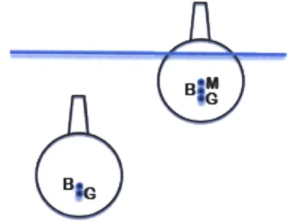
Next, for the static object to float upright and resist the tendency to roll or capsize, the NPMS is said to have achieved transverse stability when the moments about the longitudinal x-axis have been balanced. In the submerged state, this condition occurs when the center of gravity of the submarine is located below, and in a vertical line with, the center of buoyancy. The distance between these two points is quantified as the BG (Figure 14). On the surface, however, the submarine will behave just as a surface ship where transverse stability is dependent upon the center of gravity being located below the metacenter. This imaginary point represents the intersection of vertical lines through the center of buoyancy as it moves laterally, tracing an arc in response to "tilting" of the vessel. The distance between the metacenter and center of gravity is referred to as the GM. Both of these quantitative indicators of stability will be discussed in detail shortly, but in summary, these values indicate the NPMS's ability to remain upright. The larger the values, the "more" stable or difficult to overturn and smaller values are indicative of a vessel more likely to roll over.
Figure 14 - Transverse Stability (Submerged and Surfaced)
Lastly, to have a submarine achieve longitudinal stability it is necessary to balance the resulting moments in the y-z plane, causing the vessel to be in "trim". For this to occur, the longitudinal center of gravity (LCG) must fall vertically in-line with the longitudinal center of buoyancy (LCB). Initially, this is often achieved through an accurate estimate of internal weights and the intentional placement of static lead ballast. During operations, this "see-saw" (Figure 15) must be continually maintained by the flooding or emptying of the forward and aft ballast tanks, either separately or in tandem.
Figure 15 - Longitudinal Stability
In summary, just like conventional submarines, the NPMS too must simultaneously satisfy all of these conditions in order to achieve initial static stability. However, this case represents a unique problem. First, due to its many free-flooded compartments, the NPMS is inherently negative, whereas an enclosed volume of similar size and weight would float. Without numerous buoyancy PODs, the NPMS would be unable to satisfy Archimedes' principle and would promptly sink. Second, transverse stability requires precise record keeping and the creative placement of the numerous essential electronic systems and batteries. However, the optimized NPMS does not require additional, consumable materials for extended patrol, does not have any berthing considerations, or carry ordnance. By comparison, the change in variable load is extremely small. Lastly, the NPMS was intentionally design without lead or purely fixed ballast and incorporates a single forward and aft ballast system to both submerge and induce proper trim. These considerations both act to simplify and complicate the design and create an interesting analysis problem.
5.2 Submerged Stability
In order to ensure that the center of gravity remains below the center of buoyancy, accurate and comprehensive knowledge of the locations, weights, and volumes of all components within the craft was necessary. By accounting for all of the original weights and centers, this data was modified accordingly to reflect new and relocated items. This required the development of an extensive spreadsheet to organize and calculate critical design factors.
One principle value of stability is the craft's BG, or the vertical distance from the center of gravity to the center of buoyancy. With the NPMS in the defined light configuration, the BG was determined to be only 5.84% less than the reported baseline SDV value, a completely acceptable value in terms of stability. If mission constraints required the installation of the more dense H-100 Divinycell foam, the BG changed slightly: 6.60% less than the reported baseline SDV value. Both of these values for BG adequately satisfy the submerged stability requirement and represent a transversely stable craft despite the robust enhancement in capability and loading capacity.
Finally, in the submerged state, trim can be achieved when the forward tank is filled to 60% of capacity and the aft tank at 82% capacity.
In emergency situations, complete activation of the OBT would cause the proposed NPMS to proceed rapidly to the surface with a positive bow angle of 6.58 degrees. This
"nose up" orientation is extremely desirable for both operational and safety concerns.
5.3 Surface Stability
Imagine that the NPMS of the previous section has emerged from below and is now resting on the surface. The tanks possess the same trim settings and the OBT has been fully activated and is now void of ambient seawater. Many important questions must now be answered to determine the practicality of the design: At what draft will it sit and at what attitude? Will it remain upright or roll over? What angle of inclination could cause it to roll over? What is the corresponding roll period? The purpose of this section is to specifically address these important unknowns.
To best answer these questions and illustrate the performance and stability of the proposed NPMS over a range of draft values and loads, naval architects developed a system of complex, superimposed graphs known as the Curves of Form (COF). This helpful tool allows the viewer to observe changes or trends of specific parameters as a function of draft and then extract specific hydrostatic values such as displacement, area of water-plane, and changes in the location of the center of buoyancy. The generation of the Curves of Form for the optimized NPMS and illustration of overall surface stability will be the goal of Section 5.3.
5.3.1 Approach
In order to determine the fundamental design parameters, it was first necessary to choose an overall methodology which would best account for the size, many free-flooded spaces, and irregular internal arrangement of the NPMS. This began by efficiently utilizing the detailed, three dimensional computer model developed over several months. With this critical tool, an overall approach was then decided. Instead of tackling the problem from the outside, analyzing the vessel's envelope and then subtracting "non-contributing" free flooded spaces, this analysis would progress best from the inside-out. By carefully organizing the known quantities (weight, volume, and location) of each significant, "contributing" part, we created a framework which mathematically combines pieces such as battery boxes, ballast tanks, electronic canisters, and other large internal structures into one body (Figure 16). This product omits the prevalent free flooding spaces and efficiently handles the irregular, internal geometry.
Figure 16 -Contributing Internal Pieces
Next, it was time to attack the overall analysis. Two traditional methods were at our disposal: dividing the vessel longitudinally, known as the sectional approach, or dividing it along the vertical axis, known as the water-plane method. In the end, the latter choice, in concert with the three dimensional model, offered a desirable combination of simplicity and accuracy, although both would have provided the same end results. The water-plane method causes the observer to look at incremental "slices" of the vessel in the x-y plane, as illustrated in Figure 17. This approach was used to determine values such as area, volume, centroids, and moments of inertia for the vessel, as function of draft. Finally, these quantities were then used to develop the Curves of Form.
Figure 17 - One of the Numerous, Incremental "Slices" (Mid-Z Axis)
Using the trapezoidal integration method, the areas of the individual "slices", or water-planes, were summed. This equation provided the entire volume of our framework body, minus free flooded space:
V <uw =
S
(!Awpi + ZW- Awpi + !Awpn)Equation 2
where Fuw is the underwater volume of the craft, S is the "slice" thickness, conveniently set to 1", and AwP is the computer generated value for the water-plane area for every "n" slices along the z-axis. As a check, this approximation was later compared to the exact one reported by the computer. The values differed by less than one percent. This initial congruence provides credibility to future calculations determined by this overall approach.
Having the underwater volume, Vuw, as a function of the water-plane, the displacement, A, in both salt and fresh water was then calculated.
A(FLUID) =
VUW
* Pa(FLUID)Equation 3
Creating the first of many graphs to come, the draft was then plotted against the displacement of the NPMS, resulting in Figure 18:
Percent of Maximum Vehicle Height 100% -98% 96%-94% 92% 9096 88% 86% 84% 105%
Draft Versus Displacement
110% 115% 120% 125% ----) SP %W ( bs NW) - DISP FW (lbs FW) Displacement as a Percentage of Baseline 130% Vehicle Displacement
Figure 18 - Draft versus Displacement (Non-Dimensional)
Using Archimedes' principle, it was at the intersection of this displacement curve and the vessel's mission weight which provided the draft at which the NPMS would ultimately float. Thus, the NPMS in the light condition, weighing 116% the baseline SDV Mk8 Mod1 value, will float at a draft equal to 89% of her total height. This draft value is referred to as the design waterline, or DWL. An illustration, as seen from the perspective of an observer on the surface, is provided in Figure 19. Utilizing this graph, future mission planners could determine the DWL of the NPMS under various mission loads.
Figure 19 -Proposed NPMS, Surfaced at DWL
PPF'
5.3.2 Stability Parameters
Similarly, other values were needed Specifically, values such as KB, KM, Immersion, BML, and Moment to Trim graphs found in Appendix C.
to develop the GM, BG, LCB, 1" were included
complete Curves of Form. Awp, LCF, Pounds Per Inch in the NPMS Curves of Form
Traditionally, as a precursor to these quantities, Awp, the centroids, the Moments of Area and the Moments of Inertia must be determined for each individual water-plane. These values are produced mathematically if given a formula is known, which approximates the curve of the vessel's hull. Often being an irregular shape, measured points along the hull are organized into a table of offsets, allowing a "best fit" or spline curve to be generated, which serves to approximate its shape.
By this method, the first value to find would be the Awp, which is determined by integrating below the curve, along the x-axis, from the bow to the stern. Symmetry about this axis, typical of most ships, allows this hull-curve integration to be doubled and will provide the area of the water-plane via the following (Edward V. Lewis, 1988):
ST ERN
Awp = 2 fSow
Equation 4
The centroids, referenced from the y Lewis, 1988):
and x axis, respectively, are found by (Edward V.
STERN
xydx
fSoERNyd Equation 5 STERN 2dx
STERN Equation 6where, if the vessel is symmetric about the x-axis, Y = 0.
Next, the Moments of Area about a prescribed axis may be found by the following equations (Edward V. Lewis, 1988):
f
STERN M(Y-As) = fBOW Equation 7 -STERNy
2dx M(x-AMS) = fBOw Equation 8Lastly, the Moments of Inertia are given by the following (Edward V. Lewis, 1988):
I(Y-AXJS) = SERN x2
ydx
Equation 9
STERN2
I(X-AXS) = fBoE
y
2dydx
Equation 10Fortunately, this tedious process was not required for each of the numerous water-planes. These seven critical quantities were provided directly from the computer model. This method was highly advantageous for its speed and level of accuracy. Using these values, important surface stability parameters for the NPMS were calculated. In order to find KB, the vertical center of buoyancy, the following equation was used (Edward V. Lewis, 1988): AT
K
0
TAwpdT
KB = V(uw) Equation 11Conveniently, the computer generated values for Ix and Iy were centered about the centroids of the water-plane, instead of the customary orientation about the x and y reference axis, respectively. Had the latter been the case, the parallel axis theorem would have been required to convert those parameters to IT and IL. This this was not required, direct substation of these values allowed BMT and BML to be computed at the DWL by the following (Mark Welsh, 2010):
BMT= IT/ | 7
(UW)
Equation 12
BML = IL / V(UW)
Equation 13
KM, the distance from the keel to the metacentric height, could be determined (Mark Welsh, 2010):
KM = KB +BMT
Equation 14
KG was determined from the extensive weight balance spreadsheet created for the proposed design. Since the center of gravity was based on internal arrangement and location of masses, it is constant for a given geometry and does not change as a function of draft. Considering the framework consisting of the "significant" individual parts described earlier, the vertical center of gravity, KG was computed at 34.42% of the total vessels height. The longitudinal center of gravity, LCG, was found to be 45.42% of the total vessel's length. Both values are acceptable results.
Finally, we can compute the last of our fundamental parameters, GM and BG (Mark Welsh, 2010): GM = KM - KG Equation 15 BG = KG - BG Equation 16 Page 39 of 70
Knowing these values, the last of our parameters can be computed (Mark Welsh, 2010): STERN LCF = 8 y Awp Equation 17 STERN
SNOW
xAwpdx LCB = Equation 18By convention, LCF and LCB are both normally referenced aft of amidships. The next quantity is the amount of weight necessary to cause the ship to sink one-inch, and is typically given by (Mark Welsh, 2010):
TPI = AwP
/
420Equation 19
Due to the size of NPMS units of pounds per inch was more appropriate for an
application of this magnitude. TPI was converted to PPI by multiplying by 2240. The final parameter, the moment required to cause a change in trim by one-inch, is given by (Mark Welsh, 2010):
MT1" = (GML *
A) /
12LThese preceding equations and methodology provide the following parameters for the optimized NPMS:
Stability
Parameters Summary
Surfaced (@ DWL)
DWL Location
GM
KM
KG
LCG
KB
LCB
BM
T
BM L
Roll Coefficient
Roll
Period
Surface Pitch Angle
Submerged
BG
KB
LCB
Ascent
Angle
Ballast Trim Values
(Light Configuration)
88% of Maximum Vehicle Height
2.51 inches
22.36 inches
19.85 inches
115-82 inches
20.78 inches
115.85 inches
1.58 inches
26.58 inches
0.40 secIft
12
2.75 seconds
-1.66 degrees (bow down)
(Light Configuration)
3.71 inches (H-80) 3.68 (H-100)
25.27 inches
115.20 inches
6.58 degrees (bow up)
FWD: 60% Full AFT 80% Full
Table 3 - Stability Parameters (Surfaced and Submerged)
5.3.3 Curves of Form
The goal of the previous two sections was to determine those performance and stability parameters required for the Curves of Form. Appendix C will present them in both layout and format analogous to those of larger naval vessels. Typically, the Curves of Form appear as a single chart of numerous superimposed curves, but to improve clarity and viewing ease, it was divided into two distinct sections. On both graphs, the units on the horizontal axis are displacement in pounds, as a percentage of the original baseline displacement of the SDV Mk8 Mod-1. The vertical axis is the proposed vessel's draft in inches, as a percentage of the total height.
At first glance, the shape and erratic nature of the second graph may be alarming. However, after considering the cross section of the NPMS in Figure 20, it is logical given the arrangement of the significant, "contributing" interior components.
Figure 20 - NPMS Cross and Planar Section
This complicated arrangement explains why at lower draft values, the value for Awp, for example, is considerably larger than at the medium draft levels. Typically, this would not be the case. It then increases again considerably in magnitude higher on z-axis values, closer to the design waterline. The parameters in the second graph are highly dependent on Awp, and closely follow this trend accounting for the dynamic appearance.
5.3.4 Surface Stability Conclusions
Static surface stability has been met by complying with our initial three requirements. The first requirement allowed us to determine the design waterline, or DWL, for various loads and show that the proposed design would float. Initial transverse stability was illustrated having the vertical center of gravity, KG, always below the metacentric height, always possessing a positive GM value.
DWL
Relative Locations (Not to Scale) X
Figure 21 - Locations of K, B, G, and M (Surfaced)
Additionally, the righting arm curve in Figure 22 was developed for transverse angles of inclination. The first line (in blue) indicates that the righting arm, GZ, will be sufficient for small angle disturbances (Edward V. Lewis, 1988), recalling the initial calm water assumption. The second curve (in red) is the wall sided approximation (Moore, 2010) which is may be applied given the "square" cross section of the NPMS. Using this approximation illustrates further transverse stability at even larger angles. Due to both the orientation and capacity of the two ballast tanks, the free surface effect was determined to be negligible.
GZ
=
GM
sin(O)
3 2.5 2 --GZ 1.5 00 G 1.5 -GZ (Wall-Sided Approx) 1 GM(Max) 0.5 0 0 10 20 30 40 50 60 0 (degrees)Figure 22 - Righting Arm Curve for the Surfaced NPMS
Finally, the third stability requirement allows us to determine the surface attitude of the NPMS. With the OBT completely activated and ballast tanks filled as in the submerged trim condition, she will sit on the surface at the DWL with a downward bow angle of 1.66 degrees, an acceptable value for both operational and safety concerns. Although the majority of time underway is spent beneath the surface, routine surface operations are also extremely important and necessitate the ability to perform on the surface. These include swimmer deployment, reconnaissance missions,
and various emergency procedures.
5.4 Equilibrium Polygon and Mission Loading Conditions
Due to the small size and configuration of the current SDV, mission loading becomes a fine art, balancing operational desires with hydrostatic fundamentals. Every item placed within the craft, including divers, affects the balance of moments and forces
necessary for stability.
To visually depict this balance, naval architects employ an aid known as the equilibrium polygon. The lines of the resulting shape represent the boundaries of the vessel's ability to shift variable ballast and compensate for the magnitude and location
of various internal loads.
Figure 23 is the equilibrium polygon for our proposed design, depicting the most extreme cases for both payload and environmental ranges that can be accommodated. The blue border illustrates the limitations of the SDV Mk8 Mod1 to compensate for internal shifts in weight; the red is indicative of the improved capability of the propose