HAL Id: hal-00168519
https://hal.archives-ouvertes.fr/hal-00168519
Submitted on 29 Aug 2007
HAL is a multi-disciplinary open access
archive for the deposit and dissemination of
sci-entific research documents, whether they are
pub-lished or not. The documents may come from
teaching and research institutions in France or
abroad, or from public or private research centers.
L’archive ouverte pluridisciplinaire HAL, est
destinée au dépôt et à la diffusion de documents
scientifiques de niveau recherche, publiés ou non,
émanant des établissements d’enseignement et de
recherche français ou étrangers, des laboratoires
publics ou privés.
Working and Assembly Modes of the Agile Eye
Ilian Bonev, Damien Chablat, Philippe Wenger
To cite this version:
Ilian Bonev, Damien Chablat, Philippe Wenger. Working and Assembly Modes of the Agile Eye.
IEEE International Conference On Robotics And Automation, May 2006, Orlando, United States.
pp.2317-2322. �hal-00168519�
hal-00168519, version 1 - 29 Aug 2007
Working and Assembly Modes of the Agile Eye
Ilian A. Bonev
Damien Chablat and Philippe Wenger
D´epartement de g´enie de la production automatis´ee
Institut de Recherche en Communications
´
Ecole de Technologie Sup´erieure
et Cybern´etique de Nantes,
1100 Notre-Dame St. West, Montr´eal, QC, Canada H3C 1K3
1 rue de la No¨e, 44321 Nantes, France
[email protected] {Damien.Chablat, Philippe.Wenger}@irccyn.ec-nantes.fr
ABSTRACT
This paper deals with the in-depth kinematic analysis of a special spherical parallel wrist, called the Agile Eye. The Agile
Eye is a three-legged spherical parallel robot with revolute
joints in which all pairs of adjacent joint axes are orthogonal. Its most peculiar feature, demonstrated in this paper for the first time, is that its (orientation) workspace is unlimited and flawed only by six singularity curves (rather than surfaces). Furthermore, these curves correspond to self-motions of the mobile platform. This paper also demonstrates that, unlike for any other such complex spatial robots, the four solutions to the direct kinematics of the Agile Eye (assembly modes) have a simple geometric relationship with the eight solutions to the inverse kinematics (working modes).
I. INTRODUCTION
Most of the active research work carried out in the field of parallel robots has been focused on a particularly challenging problem, namely, solving the direct kinematics, that is to say, finding each possible position and orientation of the mobile platform (assembly mode) as a function of the active-joint variables. A second popular problem has been the evaluation and optimization of the workspace of parallel robots [1], [2]. Unfortunately, the direct kinematic problem and the workspace analysis have most often been treated independently, although they are closely related to each other.
It is well known that most parallel robots have singularities in their workspace where stiffness is lost [3]. These singu-larities (called parallel singusingu-larities in [4] and Type 2 in [3]) coincide with the set of configurations in the workspace where the finite number of different direct kinematic solutions (assembly modes) changes. For parallel manipulators with several solutions to the inverse kinematic problem (working
modes), another type of singularity exist and defines what may
be generalized as the workspace boundary. These singularities (called serial singularities in [4] and Type 1 in [3]) coincide with the set of configurations in the workspace where the finite number of different inverse kinematic solutions (working modes) changes. While ensuring that a parallel robot stays with the same working mode along a discrete trajectory is straightforward, the notion of “same assembly mode” is not even clear in the general case. Indeed, the direct kinematic solutions are most often obtained by solving a univariate polynomial of degree n > 3, which means that there is no
way to designate each solution to a particular assembly mode.
Then, how does one choose a direct kinematic solution for a parallel robot for each different set of active-joint variables?
A natural sorting criterion is that the direct kinematic solution could be reached through continuous motion from the initial assembly mode, i.e., the reference configuration of the robot when it was first assembled, without crossing a singular-ity. Before [5], it was commonly thought that such a criterion was sufficient to determine a unique solution. Unfortunately, as for serial robots [5], [6], a non-singular configuration changing trajectory may exist between two assembly modes for robots that are called cuspidal. This result later gave rise to a theoretical work on the concepts of characteristic surfaces and uniqueness domains in the workspace [7]. However, it still remains unknown what design parameters make a given parallel robot cuspidal, and it is still unclear how to make a given parallel robot work in the same assembly mode. It will be shown in this paper, that there is a spherical parallel robot (quite possibly the only one), for which there are clear answers to these complex questions.
From the family of parallel wrists [8], the Agile Eye provides high stiffness and is quite probably the only one to provide a theoretically unlimited and undivided orientation workspace. The Agile Eye is a 3-RRR spherical parallel mechanism in which the axes of all pairs of adjacent joints are orthogonal. Based on the Agile Eye design, a camera-orienting device was constructed at Laval University a decade ago [9], an orientable machine worktable was manufactured at Tianjin University, and a wrist for a 6-DOF robot was built at McGill University. The Agile Eye has been extensively analyzed in literature, but surprisingly some of its most interesting features have not been noticed. One of the key references in this paper is [10], where the simple solution to the direct kinematics of the Agile
Eye is presented. Namely, it is shown that the Agile Eye has
always four trivial solutions (at which all three legs are at singularity and can freely rotate) and four nontrivial solutions obtained in cascade. A second key reference is [11], where the singularities of the Agile Eye are studied. Unfortunately, in [11], it was mistakenly assumed that the only singular configurations are the four trivial solutions (orientations) to the direct kinematics. Basically, the fact that at each of these four orientations, a special arrangement of the legs can let the mobile platform freely rotate about an axis was overlooked. Indeed, as this paper shows, the singularities of the Agile Eye are six curves in the orientation workspace corresponding to self motions of the mobile platform or lockup configurations.
x y z u 2 u 3 u 1 v 1 w2 w 3 v 2 w 1v3 O
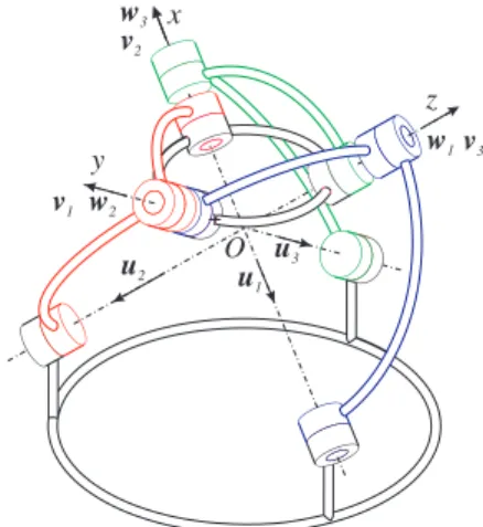
Fig. 1. The Agile Eye at its reference configuration.
When it was realized that the unlimited workspace of the
Agile Eye is not divided by singularity surfaces (as is the case
for all other spherical parallel robots), yet accommodating four unique assembly modes, it first seemed that the Agile Eye is a cuspidal robot. In this paper, it is shows not only that the Agile
Eye is not cuspidal, but that it is straightforward to identify its
four assembly modes via a simple relationship to its working modes. The results of this paper provide more insight into the kinematics of the Agile Eye and shed some light to the open problem of assembly mode designation.
The rest of the paper is organized as follows. In the next two sections, the kinematic model of the Agile Eye and its inverse kinematics are presented briefly. Then, the direct kinematics and the singularity analysis of the Agile Eye are addressed by partially reproducing, reformulating, and augmenting the results of [10] and [11]. Finally, it is shown that for each working mode there is a single corresponding assembly mode from among the four nontrivial ones.
II. KINEMATICMODEL OF THEAGILEEYE
Figure 1 depicts the Agile Eye at its reference configuration, where the mobile platform is at its reference orientation and all active-joint variables are zero. At the reference configuration, the axes of the first base joint, the second intermediate joint, and the third platform joint coincide, and so on for the other joints (the figure is self-explanatory).
A base reference frame Oxyz is chosen in such a way
that its x axis is along the axis of the first base joint, its y axis is along the axis of the second base joint, and its z
axis is along the axis of the third base joint, as shown in Fig. 1. A mobile reference frame (not shown) is fixed at the mobile platform so that it coincides with the base frame at the reference orientation. With these settings, the axes of the base joints are defined by the following unit vectors expressed in the base reference frame:
u1= 1 0 0 , u2= 0 1 0 , u3= 0 0 1 . (1)
Similarly, the axes of the platform joints are defined by the following unit vectors expressed in the mobile reference frame:
v′ 1= 0 −1 0 , v′ 2= 0 0 −1 , v′ 3= −1 0 0 . (2)
The rotation matrix R describes the orientation of the mobile frame with respect to the base frame. The ZYX Euler-angle convention is used here because it simplifies greatly the kinematic analysis. In the base frame, the axes of the platform joints are defined as follows
vi= Rv′
i = Rz(φ)Ry(θ)Rx(ψ)v′i, (3)
wherei = 1, 2, 3, which yields
v1 =
sin φ cos ψ − cos φ sin θ sin ψ − cos φ cos ψ − sin φ sin θ sin ψ
− cos θ sin ψ , v2 =
− sin φ sin ψ − cos φ sin θ cos ψ cos φ sin ψ − sin φ sin θ cos ψ
− cos θ cos ψ , v3 = − cos φ cos θ − sin φ cos θ sin θ . (4)
Finally, the axes of the intermediate joints are defined by the following unit vectors expressed in the base reference frame:
w1= 0 − sin θ1 cos θ1 , w2= cos θ2 0 − sin θ2 , w3= − sin θ3 cos θ3 0 , (5)
where θi is the active-joint variable for leg i (in this paper
i = 1, 2, 3).
III. INVERSEKINEMATICS ANDWORKINGMODES
Although very simple, the solutions to the inverse kinemat-ics of the Agile Eye will be presented for completeness [10]. For a given orientation of the mobile platform, each leg admits two solutions forθi in(−π, π] obtained from
tan θ1 =
cos θ sin ψ
cos φ cos ψ + sin φ sin θ sin ψ, (6) tan θ2 =
sin φ sin ψ + cos φ sin θ cos ψ
cos θ cos ψ , (7)
tan θ3 = tan φ. (8)
Thus, the inverse kinematic problem usually admits eight real solutions or working modes for any (non-singular) orien-tation of the mobile platform. It is very important to note that for both solutions forθi, vector wiis along the same axis but
with opposite directions. When a leg is fully extended or fully folded, the corresponding equation from the above three ones does no hold true and the corresponding active-joint variable
IV. DIRECT KINEMATICS ANDASSEMBLYMODES
The Agile Eye was optimized to have maximum workspace and global dexterity [9]. Incidentally, such properties also yield great simplification in the direct kinematic problem because the eight solutions for a general 3-RRR parallel wrists degenerate to four trivial and four nontrivial ones. The direct kinematics of the Agile Eye was solved in [10] and will be reformulated and further analyzed here.
The following constraint equations are written:
wTi vi= 0, (9a) thus
sin ψ(sin θ1sin θ sin φ − cos θ cos θ1) +
cos ψ sin θ1cos φ = 0, (9b)
cos ψ(cos θ2sin θ cos φ − cos θ sin θ2) +
sin ψ cos θ2sin φ = 0, (9c)
sin(θ3− φ) cos θ = 0. (9d)
From Eq. (9d), the direct kinematic problem is found to admit two sets of solutions, defined by
cos θ = 0, and (10a)
sin(θ3− φ) = 0. (10b)
In the next two subsections, these two equations will be solved.
A. First Set of Solutions — Trivial Solutions
Equation (10a) gives two solutions for the angleθ, θ = π/2 and θ = −π/2, (11) which both correspond to a representation singularity in the
XY Z Euler angles. From the first solution and after
sim-plification of Eq. (9b), the following condition is found for arbitrary active-joint variables,
cos(φ − ψ) = 0, (12) and from the second solution,
cos(φ + ψ) = 0. (13) In both cases, each of these two equations lead to two solutions. Thus, because of the representation singularity, only four rotation matrices describe the corresponding orientations of the mobile platform:
RT O1= 0 −1 0 0 0 1 −1 0 0 , RT O2= 0 1 0 0 0 −1 −1 0 0 , RT O3= 0 −1 0 0 0 −1 1 0 0 , RT O4= 0 1 0 0 0 1 1 0 0 .
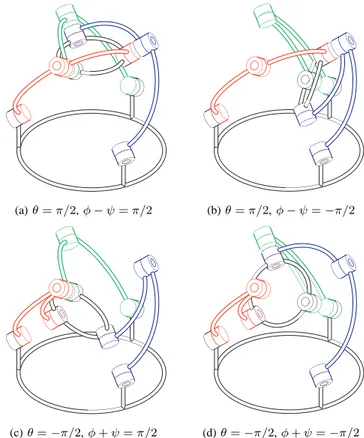
Figure 2 depicts the four trivial solutions (orientations) to the direct kinematic problem. It may be seen geometrically, as well as from Eqs. (9b-d), that when the platform is at one of these four orientations, all three legs are at a singularity (fully extended or folded) and can freely rotate about their base joint
(a)θ = π/2, φ − ψ = π/2 (b)θ = π/2, φ − ψ = −π/2
(c)θ = −π/2, φ + ψ = π/2 (d)θ = −π/2, φ + ψ = −π/2
Fig. 2. The four trivial solutions to the direct kinematic problem valid for any set of active-joint variables but shown withθ1= 0, θ2= 0 and θ3= 0. axes. Thus, these four orientations are trivial solutions to the direct kinematic problem of the Agile Eye and exist for any set of active-joint variables. These four families of configurations will be discussed further in the section on singularity analysis.
B. Second Set of Solutions — Nontrivial Solutions
Equation (10b) gives two solutions for the angleφ: φ = θ3 and φ = θ3± π. (14)
However, in the ZYX Euler-angle convention, the triplets
{φ, θ, ψ} and {φ ± π, −θ ± π, ψ ± π} both correspond to the
same orientation. This means that the above two solutions will lead to the same orientation of the mobile platform. Hence, only the first solution will be used in this paper.
Substituting φ = θ3 in Eqs. (9b-c), a new system of two
equations is obtained:
p1cos ψ + p2sin ψ = 0, (15a)
p3cos ψ + p4sin ψ = 0, (15b)
where
p1 = sin θ1cos θ3, (15c)
p2 = sin θ1sin θ sin θ3− cos θ cos θ1, (15d)
p3 = cos θ2sin θ cos θ3− cos θ sin θ2, (15e)
p4 = cos θ2sin θ3. (15f)
Since the termscos ψ and sin ψ cannot vanish simultaneously,
Eqs. (15a-b) lead to
Solution 1 φ θ ψ
Solution 2 φ θ ψ + π
Solution 3 φ θ + π −ψ
Solution 4 φ θ + π −ψ + π
TABLE I
THE FOUR NONTRIVIAL SOLUTIONS TO THE DIRECT KINEMATIC PROBLEM
Hence, substituting Eqs. (15c-f) into the above equation gives
cos θ(q1cos θ + q2sin θ) = 0, (17a)
where
q1 = sin θ1cos θ2cos θ3sin θ3− cos θ1sin θ2, (17b)
q2 = sin θ1sin θ2sin θ3+ cos θ1cos θ2cos θ3. (17c)
Equation (17a) leads to two possibilities:
cos θ = 0 and (18a)
q1cos θ + q2sin θ = 0. (18b)
Equation (18a) is the same as Eq. (10a) and will therefore be discarded. Equation (18b) gives two solutions in (−π, π]:
θ = tan−1(−q1/q2) + kπ with k = 0, 1. (19)
Equations (15a-b) can now be used to findψ: ψ = tan−1(−p1/p2) + kπ with k = 0, 1, or
ψ = tan−1(−p
3/p4) + kπ with k = 0, 1,
which gives two values for ψ in (−π, π] for each θ.
Table I summarizes the solutions to the direct kinematic problem, where a number to each solution is arbitrarily as-signed. An example of four nontrivial solutions to the direct kinematic problem of the Agile Eye is given in Fig. 3 for the active-joint variablesθ1= −0.3, θ2= −0.7 and θ3= 0.1.
Later, a method will be presented to identify these nontrivial solutions based on the working mode. For now, note by solely observing Fig. 3 that these four nontrivial solutions are obtained from each other by rotating the mobile platform about a platform joint axis at 180 degrees (in fact, the same is true for the four trivial solutions). Thus, if for a given set of active-joint variables, there is one nontrivial solution, then there are (at least) three other nontrivial solutions. The important question whether there are always four nontrivial solutions was not answered in [11] and will be given special attention now.
C. Degenerate Cases
The second set of solutions will become the same as the first set of solutions when Eq. (18b) degenerates andq2= q1= 0.
It can be shown that q2 = q1 = 0 if and only if sin θ2 = 0
and cos θ3 = 0, or sin θ3 = 0 and cos θ1 = 0. In that case,
θ can be anything, which is one of the self-motions of the
mobile platform. If q2 = 0 but q1 6= 0, Eq. (18b) becomes
w 1 w 2 w 3 (a) φ = 0.100, θ = −0.672, ψ = −0.383 w 1 w 2 w 3 (b)φ = 0.100, θ = −0.672, ψ = 2.759 w 1 w 2 w 3 (c) φ = 0.100, θ = 2.470, ψ = 0.383 w 1 w 2 w 3 (d) φ = 0.100, θ = 2.470, ψ = 3.525
Fig. 3. The four nontrivial solutions to the direct kinematic problem of the
Agile Eye forθ1= −0.3, θ2= −0.7 and θ3= 0.1.
identical with Eq. (18a), meaning thatθ = ±π/2. Substituting θ = ±π/2 into Eqs. (15a-b) yields
sin θ1cos(φ ∓ ψ) = 0 and cos θ2cos(φ ∓ ψ) = 0. (20)
If sin θ1 = 0 and cos θ2 = 0, (φ ∓ ψ) is arbitrary, meaning
that the platform can undergo a self motion. If, however, these two conditions are not satisfied, thencos(φ ∓ ψ) = 0, which
means that the only direct kinematic solutions are the trivial ones.
Thus, in summary, the Agile Eye will have only the four trivial solutions to its direct kinematic problem if and only if
q2= sin θ1sin θ2sin θ3+ cos θ1cos θ2cos θ3= 0, (21)
but neither of the following three pairs of conditions is true:
sin θ2= 0 and cos θ3= 0, or (22a)
sin θ3= 0 and cos θ1= 0, or (22b)
sin θ1= 0 and cos θ2= 0. (22c)
Taking the first pair yieldsq2= 0 and q1= 0, meaning that
θ can take any value. This means that there is a self motion
— even if all actuators are fixed, the platform can freely move. Substituting θ2 = 0 or θ2 = π, and θ3 = ±π/2 into
Eqs. (15a-b), yieldssin ψ = 0. In addition, cos φ = cos θ3= 0.
Similarly, for the second pair of conditions, it can be proved that θ can have any value, while cos ψ = 0 and sin φ = 0.
Finally, taking the third pair of conditions,q2= 0 but q16= 0,
Eq. 17a implies that cos θ = 0. If this pair of conditions is
(a) (b)
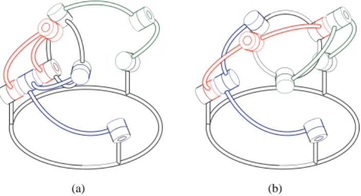
Fig. 4. The two self motions of the mobile platform where leg 3 is singular.
thatsin(φ − ψ) can be anything in the case of θ = π/2 or that sin(φ + ψ) can be anything in the case of θ = −π/2.
Thus, it can be easily shown that Eqs. (22a–c) correspond to six self motions represented by the following rotation matrices (where angles are arbitrary):
RSM 1a = 0 −1 0 cos θ 0 sin θ − sin θ 0 cos θ , (23a) RSM 1b = 0 1 0 cos θ 0 − sin θ − sin θ 0 − cos θ , (23b) RSM 2a = cos θ sin θ 0 0 0 −1 − sin θ cos θ 0 , (23c) RSM 2b = cos θ − sin θ 0 0 0 1 − sin θ − cos θ 0 , (23d) RSM 3a = 0 − sin(φ − ψ) cos(φ − ψ) 0 cos(φ − ψ) sin(φ − ψ) −1 0 0 , (23e) RSM 3a = 0 − sin(φ + ψ) − cos(φ + ψ) 0 cos(φ + ψ) − sin(φ + ψ) 1 0 0 . (23f)
Now, note that each of the pairs of conditions imposes a constraint on two of the active-joint variables, while the third one can take any value, without influencing the orientation of the mobile platform. This means, that in the above self-motions, there is a leg in singularity. In fact, the self-motion of the platform is about the axis of the base joint of the leg in singularity. The above self motions are divided into pairs, where in each pair, one of the motions correspond to a fully extended leg (the ones with the b index), while the other to a fully folded one. Figure 4 shows the two self motions (SM3a and SM3b) for which leg 3 is singular, corresponding to the pair of conditions of Eq. (22c). In this figure, legs 1 and 2 are each shown in one of the possible two configurations per leg. As will be seen in the next section, all singular config-urations were found in this section by purely studying the degeneracies of the direct kinematics of the Agile Eye.
V. SINGULARITYANALYSIS
The relationship between the active-joint rates, ˙θ, and the angular velocity of the mobile platform, ω, can be written as:
Aω+ B ˙θ = 0 (24) where A and B are Jacobian matrices and can be written as
A= (w1× v1)T (w2× v2)T (w3× v3)T = αT1 αT2 αT3 , (25a) B= (w1× v1)Tu1 0 0 0 (w2× v2)Tu2 0 0 0 (w3× v3)Tu3 . (25b)
Type 2 singularities are characterized by studying matrix
A and occur whenever the three vectors αi are coplanar or
collinear. For the Agile Eye, these vectors cannot be collinear. Thus, when these three vectors are coplanar, the platform can rotate (infinitesimally or finitely) about the axis passing through the centerO and normal to the plane of the vectors.
Substituting the nontrivial solution set for the direct kine-matics of the Agile Eye into the determinant of A of Eq. (25a) and simplifying, it is obtained that the expression in the active-joint space for Type 2 singularities is:
det(A) = sin θ1sin θ2sin θ3+ cos θ1cos θ2cos θ3= 0. (26)
Substituting the trivial solution set yields the same expres-sion but with a negative sign. Note that the determinant of A is the same for all four assembly modes. This is not surprising since from the geometric interpretation of the four assembly modes, it can be seen that between any two assembly modes, two pairs of vectors αi have opposite directions and the third
pair is the same.
Type 1 singularities are characterized by studying matrix B and occur whenever a leg is fully extended or folded. For a general 3-RRR spherical parallel mechanism with legs of other than 90 degrees, Type 1 singularities are two-dimensional entities. In other words, for such a general parallel wrist, when a single leg is singular, the platform remains with two degrees of freedom. In the Agile Eye, however, when a leg is singular, the axes of the base and platform joints coincide and the mobile platform has a single degree of freedom, whereas the leg can freely rotate without affecting the orientation of the mobile platform. Therefore, Type 1 singularities of the Agile
Eye are only six curves in the orientation space.
Substituting the nontrivial solution set for the direct kine-matics of the Agile Eye into B of Eq. (25b) and simplifying yields the following three expressions in the active-joint space, corresponding to Type 1 singularities occurring in leg 1, 2, and
3, respectively:
B11= ±
sin θ1sin θ2sin θ3+ cos θ1cos θ2cos θ3
p 1 − cos2θ 3sin 2 θ1 p 1 − cos2θ 1sin 2 θ2 = 0, (27) B22= ±
sin θ1sin θ2sin θ3+ cos θ1cos θ2cos θ3
p 1 − cos2θ 2sin 2 θ3 p 1 − cos2θ 1sin 2 θ2 = 0, (28) B33= ±
sin θ1sin θ2sin θ3+ cos θ1cos θ2cos θ3
p 1 − cos2 θ2sin 2 θ3 p 1 − cos2 θ3sin 2 θ1 = 0, (29)
where Bii is the i-th diagonal element of B, and the
plus-minus sign depends on which of the four nontrivial direct solutions is used, i.e., on the assembly mode.
Substituting the trivial solution set for the direct kinematics of the Agile Eye into B and simplifying yields as expected:
B11= B22= B33= 0. (30)
Indeed, at the trivial orientations all three legs are singular. From Eqs. (27–29), it follows that if a configuration cor-responds to a Type 2 singularity, then it should inevitably correspond to a Type 1 singularity too. However, the opposite is not necessarily true. In other words, if there is a Type 1 singularity, the Agile Eye is not necessarily at a Type 2 singularity too. Indeed, investigating the four orientations shown in Fig. 2, it can be seen that the legs can be orientated in such a way that the vectors normal to the last two joint axes in each leg are not coplanar. Such a configuration is called a lockup configuration, since the mobile platform is completely restrained even if the actuators are removed. For these four orientations, Eqs. (27–29) are replaced by Eq. (30).
Finally, it should be verified what happens, when the de-nominators of the expressions in Eqs. (27–29) are zeroed. This basically occurs when from the reference configuration, a leg is turned at90◦(in either direction), and possibly another one
is turned at180◦. It can be verified that at such a configuration,
a Type 1 singularity occurs. Indeed, the numerator of the above three equations also becomes zero.
In conclusion, the Agile Eye has the following three families of singular configurations:
• Six self motions of the mobile platform described by
Eqs. (23a–f), in SO(3), and by Eqs. (22a–c), in the active-joint space. For each self motion, one of the legs is singular. For the active-joints corresponding to each of Eqs. (22a–c), the four (nontrivial) assembly modes de-generate in pairs into the two corresponding self motions.
• Infinitely many infinitesimal motions of the mobile
platform at the four trivial orientations when the active-joints satisfy Eq. (26) but neither of Eqs. (22a–c). Each of the four trivial orientations belongs to the sets of orientations corresponding to three self motions. For the active joint variables corresponding to these singular configurations, the only solutions to the direct kinematic problem are the four trivial ones.
• Lockup configuration described in SO(3) by each of
the four trivial orientations and in the active-joint space
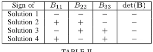
Sign of B11 B22 B33 det(B) Solution 1 − − − − Solution 2 + + − − Solution 3 − + + − Solution 4 + − + − TABLE II
THE SIGNS OFBiiFOR A GIVEN SET OF ACTIVE-JOINT VARIABLES
θ 2 θ1 θ3 det( )>0A det( )<0A (+++) (+−−) (−+−) (−−+) (++−) (+−+) (−++) (−−−)
Fig. 5. The eight assembly modes characterized by the working mode
space by anything but Eq. (26). At these Type 1 sin-gular configurations, the mobile platform cannot move even under external force. For the active joint variables corresponding to these singular configurations, the direct kinematic problem has eight solutions.
VI. WORKINGMODES ANDASSEMBLYMODES
As was mentioned before, a particularity of the Agile Eye is that the determinant of matrix A, Eq. (26), is a function of the active-joint variables only and has the same value for all four nontrivial assembly modes. Equation (26) represents a surface that divides the active-joint space into two domains where
det(A) is either positive or negative. A connectivity analysis
was made on these two domains to prove this property. The images of these two domains in the workspace yield eight identical domains (the whole orientation space without the singularity curves), each one being associated with one of the eight working modes. It can been seen geometrically, or proved algebraically, that each of the four nontrivial assembly modes correspond to a different working mode. Therefore, changing an assembly mode inevitably requires a singularity to be crossed. Hence, the Agile Eye is not cuspidal, meaning that as long as it does not cross a singularity, it remains in a single working mode and in a single assembly mode.
The eight working modes are divided into two groups. Depending on the sign of det(A), the four assembly modes
each correspond to a working mode from one of these groups. In Table II, it is assumed that for the first solution of the direct kinematic problem the sign of Bii given in Eqs. (27–29) is
negative. For the other solutions,{ψ, θ, φ} are replaced by the
value given in Table I and the influence on the sign ofBii is
shown using simple trigonometric properties. Recall that|Bii|
does not change when an assembly mode is changed. Figure 5 summarizes the behavior of the direct kinematic problem where a solution can be chosen according to the sign of Bii = (+ + +) for example and the sign of det(A).
Similarly, when the inverse kinematic model is solved, the working mode is easily characterized by the sign of Bii.
VII. CONCLUSIONS
An in-depth kinematic analysis of a special spherical par-allel wrist, called the Agile Eye, was done, pinpointing some important facts that were previously overlooked. It was demon-strated that the workspace of the Agile Eye is unlimited and flawed only by six singularity curves (rather than surfaces). Furthermore, these curves were shown to correspond to self-motions of the mobile platform. It was also proved that the four assembly modes of the Agile Eye are directly related to the eight working modes and the sign of the determinant of one of the Jacobian matrices. It was shown that as long as the
Agile Eye does not cross its singularity curves, it remains in
a single working mode and in a single assembly mode. REFERENCES
[1] C. Gosselin and J. Angeles, “The Optimum Kinematic Design of a Planar Three-Degree-of-Freedom Parallel Manipulator,” Journal of
Mechanisms, Transmissions, and Automation in Design, Vol. 110, 1988.
[2] J.-P. Merlet, “Parallel robots,” Kluwer Academic, The Netherlands, 2000.
[3] C. Gosselin and J. Angeles, “Singularity Analysis of Closed-Loop Kinematic Chains,” IEEE Transactions on Robotics and Automation, Vol. 6, No. 3, 1990.
[4] D. Chablat and P. Wenger, “Working Modes and Aspects in Fully-Parallel Manipulator,” IEEE International Conference on Robotics and
Automation, pp. 1964–1969, May 1998.
[5] C. Innocenti and V. Parenti-Castelli, “Singularity-Free Evolution from one Configuration to Another in Serial and Fully-Parallel Manipulators,”
ASME Robotics, Spatial Mechanisms and Mechanical Systems, 1992.
[6] P. Wenger, “A New General Formalism for the Kinematic Analysis of all Nonredundant Manipulators,” IEEE International Conference on
Robotics and Automation, pp. 442–447, 1992.
[7] P. Wenger and D. Chablat, “Definition Sets for the Direct Kinematics of Parallel Manipulators,” 8th International Conference in Advanced
Robotics, pp. 859-864, 1997.
[8] M. Karouia, “Conception structurale de mecanismes parall`eles sph´eriques,” PhD Thesis, RI 2003-26, ´Ecole Centrale de Paris, 2003. [9] C. Gosselin, ´E. St-Pierre, and M. Gagn´e, “On the Development of the
Agile Eye: Mechanical Design, Control Issues and Experimentation”,
IEEE Robotics and Automation Magazine, Vol. 3, No. 4, pp. 29–37,
1996.
[10] C. Gosselin and M. Gagn´e, “A Closed-Form Solution for the Di-rect Kinematics of a Special Class of Spherical Three-Degree-of-Freedom Parallel Manipulators,” Workshop on Computational
Kinemat-ics, pp. 231–240, 1995.
[11] C. Gosselin and J. Wang, “Singularity Loci of a Special Class of Spherical Three-Degree-of-Freedom Parallel Mechanisms with Revolute Actuators,” International Journal of Robotics Research, Vol. 21, No. 7, pp. 649–659, 2002.