HAL Id: hal-01537777
https://hal.archives-ouvertes.fr/hal-01537777
Submitted on 23 Jun 2017
HAL is a multi-disciplinary open access
archive for the deposit and dissemination of
sci-entific research documents, whether they are
pub-lished or not. The documents may come from
teaching and research institutions in France or
abroad, or from public or private research centers.
L’archive ouverte pluridisciplinaire HAL, est
destinée au dépôt et à la diffusion de documents
scientifiques de niveau recherche, publiés ou non,
émanant des établissements d’enseignement et de
recherche français ou étrangers, des laboratoires
publics ou privés.
Distributed path planning for controlling a fleet of
UAVs : application to a team of quadrotors
Adel Belkadi, Hernan Abaunza, Laurent Ciarletta, Pedro Castillo Garcia,
Didier Theilliol
To cite this version:
Adel Belkadi, Hernan Abaunza, Laurent Ciarletta, Pedro Castillo Garcia, Didier Theilliol. Distributed
path planning for controlling a fleet of UAVs : application to a team of quadrotors. 20th
Interna-tional Federation of Automatic Control World Congress (IFAC WC 2017), Jul 2017, Toulouse, France.
pp.15983-15988. �hal-01537777�
Distributed Path Planning for Controlling
a Fleet of UAVs : Application to a Team of
Quadrotors ⋆
A. Belkadi∗,∗∗ H. Abaunza∗∗∗ L. Ciarletta∗∗ P. Castillo∗∗∗
D. Theilliol∗
∗Universite de Lorraine, CRAN, CNRS, UMR 7039, BP 70239, 54506
Vandoeuvre Cedex, France (e-mail: adel.belkadi@univ-lorraine.fr) (e-mail: didier.theilliol@univ-lorraine.fr).
∗∗Mines Nancy, Universite de Lorraine, Loria, UMR 7503, France
(e-mail: laurent.ciarletta@loria.fr)
∗∗∗Sorbonne Universites, Universit de Technologie de Compigne,
CNRS UMR 7253, Compiegne, France (e-mail: (castillo,habaunza)@hds.utc.fr).
Abstract: In this paper, a distributed trajectory generation strategy is proposed to control
a group of Unmanned Aerial Vehicles (UAVs). The issue, treated as an online optimization problem, is solved using a Particle Swarm Optimization (PSO) algorithm. The proposed PSO is implemented independently in each vehicle in order to determine, by minimizing a cost function, the best paths that ensure the fleet formation control, target tracking and collision and obstacle avoidance. The method illustrated in this paper offers solutions to several questions related to the control of a group of UAVs and could be applied to solve problems such as covering large search areas for surveillance, inspection and rescue. Firstly, experiments on one quadrotor are implemented to illustrate the effectiveness of the proposed algorithm. Large disturbances and obstacles are considered to illustrate the robustness of the presented approach. The method is tested in a real environment with a group of three quadrotors.
Keywords: Fleet control, Flight Training, Optimization, PSO algorithm, Path generation
1. INTRODUCTION
In recent years, the control of multiple vehicles has at-tracted increasing attention from scholars around the world, owing to its potential applications whether in the military or civilian fields and by the fact that many ben-efits can be obtained when a single complicated vehicle is equivalently replaced by multiple yet simpler vehicles. To tackle this issue, two approaches are commonly adopted in literature, the first denoted centralized approach [1][2] which is a direct extension of the traditional single-vehicle control is based on the assumption that a central sta-tion controls a whole group of vehicles. The second ap-proach, called a distributed apap-proach, which is the one considered in this paper does not require a central station for control and allows for a better adaptation to many physical constraints such as limited resources, short chains of wireless communication and autonomy problems [3][4]. The recent results in this area are categorized into several directions, such as consensus (synchronization [5][6],
ren-dezvous [7][8][9]), formation control and flocking [10]−[13],
optimization [14][15], and task assignment[16][17].
⋆ Research supported by the Conseil Regional de Lorraine, the
Minist´ere de L’Education Nationale, de l’Enseignement Sup´erieur et
de La Recherche, and the National Network of Robotics Platforms (ROBOTEX), from France
In the operation of Unmanned Aerial Vehicles (UAVs), the ability to coordinate their trajectories in a multiple vehicle system is vital to carry out different type of missions. In this paper, the issue of trajectory planning is addressed for UAVs operating in a hostile environment. Specifically, the objective is to get a set of UAVs to fly on a 2D plane while converging to a predefined spatial configuration around a target point while ensuring collision and obstacle avoid-ance between team members. The approach is formu-lated as a distributed optimization problem. Each UAV is equipped with an independent optimization algorithm which, by minimizing a cost function for each UAV allows the fleet to reach the defined objectives. This distributed planning path was introduced in previous works [18][19]. In order to assume an on-line approach, it is necessary to consider an efficient optimization algorithm in terms of resource or time consuming for an embedded system. One of the best performing algorithms in this area is the Particle Swarm Optimization algorithm (PSO)[20]. The PSO has demonstrated optimal performance by min-imum search term with a minmin-imum calculation time and a relatively easy implementation. In [21] authors reported that PSO algorithm could yield significant improvement in solving Trajectory Planning Problem (TPP) and in [22] authors introduced Quantum-PSO (QPSO) to design a collision-free trajectory for planar redundant manipulator. In [23] four variants of Particle Swarm Optimization are
proposed to solve the obstacle avoidance control problem of redundant robots.
The rest of paper is organized as follows. The details of the problem formulation are discussed in Section 2. In Section 3, we present the proposed distributed path planning so-lution. Then, Section 4 illustrates the performance of the method based on various experiments. Finally, a conclu-sion and perspectives are presented in the last section.
2. PRELIMINARIES AND PROBLEM STATEMENT In general, an agent refers to a dynamic system. In this pa-per, the term ’agent’ is interchangeable with ”quadrotor”, which corresponding non-linear dynamics. Each agent is described in the state space as follows:
˙
Xi(t) = f (Xi, Ui) (1)
where Xi(t)∈ Rmand Ui(t)∈ Rk: m, k∈ N
A fleet consists of a set of agents N = 1, ..., n where n is the number of quadrotors. Information exchange among agents is modeled by an undirected graphs. Let describe system by a weighted graph G(N, ϵ(t), A(t)) where N =
1, ..., n and ϵ(t)∈ N × N are the set of nodes and the set
of arcs respectively of the graph G and A(t) a matrix of
Mn(R) of elements in R as aij(t) > 0 if : (j, i)∈ ϵ(t). At
each sample, i is an incoming neighbor of j and j is an outgoing neighbor of i.
G is assumed to be an undirected graph such as :∀(i, j) ∈ ϵ(t)⇒ (j, i) ∈ ϵ(t). In this case, matrix A(t) is symmetrical
with aij(t) = aji(t).
First of all, let us define for each i node a set of neighbors
Ξi(t) such that:
Ξi(t) ={j ∈ N : ∥xj(t)− xi(t)∥ ≤ l} (2)
where l defines the scope of the neighborhood and Ξi(t) is
called the metrical neighborhood of the agent i.
Influence between agents is represented by aij(t) elements
of the matrix A(t) such that:
aij(t) = 1 + exp ( c− dij(t) σ ) (3)
The value of the aij(t) function depends on the difference
between dij(t) the distance between two agents i and j
with the safety distance c (where c > l), and it is all the
greater when aij(t) < c and converges to the value 1 when
dij(t) >> c.
The sets of elements dij(t) representing the distances
be-tween agents forms the matrix ∂(t) at time t, and ddij the
desired distances between agents forms the matrix ∂d. It
is also assumed that each agent can detect an obstacle at
a distance l′.
The control objective is then:
(1) To bring the fleet from an initial geometrical
configu-ration ∂(t0) to a desired geometrical configuration ∂d
around a target point lim
t→+∞∂(t) = ∂d (4)
(2) Collisions between interaction agents are avoided
∀i, j ∈ N, i ̸= j : ∥xi(t)− xj(t)∥ > c (5) (3) Ensuring the obstacle avoidance
The issue is formulated as an online optimization problem where by minimizing a certain cost function it can control a fleet of UAVs. A distributed planning path strategy based on Particle Swarm Optimization (PSO) algorithm is implemented to achieve this goal and was introduced in our previous work [18][19]. In this paper, experimental tests are carried out to consolidate the theoretical part and at the same time adjustments are added to the optimization block. This includes the main contribution of this paper with obstacle avoidance part included in the control of the fleet.
3. CONTROLLERS DESIGN
3.1 Definition of the cost function
In order to define in deep the developed method, let us consider a fleet of n UAVs (of the quadrotor type)
operat-ing in the R2 space. This multiple rotary wing UAV has
four motors arranged in the form of a cross of equal sizes. Its structure offers it the advantage of vertical take off and landing, and the possibility of stationary flights.
At first, let us define a cost function Λi(t) for each U AVi
such that: Λi(t) = ρ ( ∥Pd− [xi(t) + h]∥ − ddip ) + q ∑ j=1 aij(t) ( ∥xj(t)− [xi(t) + h]∥ − ddij) ) + m ∑ k=1 Obsik(t) (6)
with i ̸= j, q = card(Ξ(t)), h ∈ R2, and ρ >> 1, dd
ip
representing the desired distance between U AViand target
point with m the number of obstacles detected by the ith UAV.
The main goal is to find the best vector h for each agent i
minimizing the cost function Λi(t) such that:
∀i ∈ N : lim
t→∞Λi(t) = 0⇒ limt→∞∂(t) = ∂d (7)
The reference trajectory at time t + τ for the agent i will then be:
Yid(t + τ ) = Yi(t) + h (8)
The ρ coefficient in the cost function should be larger than 1. This choice is due to the fact that we favor each agent
i position that tends to be in the direction of the target
point Pd.
During the evolution of the agents in R2 space,
non-collision of the agents should be ensured. This constraint
is introduced in the cost function Λi(t) through function
aij(t) which is all the greater when dij(t) < c and
con-verges to the value 1 when aij(t) >> c. So, each agent
i is more likely to favor the values of h which avoids the
need for the distances dij(t) < c and minimizes the cost
To take into account obstacle avoidance in the fleet control strategy, an additional term is introduced into the cost function such that:
Obsik(t) = exp c− ( ∥xkobs(t)− [xi(t) + h]∥) ) σ (9)
The value of the Obsik(t) function also depends on the
dif-ference between the distance between agent i and obstacle
k with the safety distance c, and it converges to zero when
the distance is much greater than the safety distance. It is assumed that the obstacle positions are unknown and are
detected at a distance dobs.
The algorithm 1 shows, in more detail, the most important steps considered in the proposed strategy to manage the fleet of UAVs.
Algorithm 1 Trajectory generation . Initialize parameters
. Define the desired configuration for the UAVs with the
matrix ∂d
repeat{at each step time}
. Calculate the matrix ∂(t)
if ((∃dij(t) < c)or(t%τ == 0)
)
then
. Find all topological neighbors for quadrotor i by
set Ξi(t)
. Detect obstacles for quadrotor i
. Minimization of the cost function Λi(t) by PSO
Algorithm
. Chose the vector h[hx, hy] that minimizes the cost
function Λi(t)
. Calculate the next position xid and yid at time
t + τ :
xid(t + τ ) = xi(t) + hx
yid(t + τ ) = yi(t) + hy
end if
until End of experimentation
3.2 Definition of the control law
In order to validate the proposed PSO algorithm in real UAVs, an appropriate position control law needs to be
selected such that the Yid (8) is correctly followed.
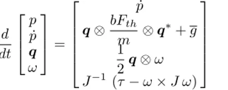
The selected scheme is a quaternion-based control, which separates the rotation and translation dynamics. Consider the vehicle’s dynamic model as
d dt p ˙ p q ω = ˙ p q⊗bFth m ⊗ q ∗+ g 1 2q⊗ ω J−1 (τ− ω × J ω) (10)
where p ∈ R3 and ˙p ∈ R3 are the vehicle’s position
and velocity vectors, Fth defines the thrust generated by
the quadrotor motors and b = [ 0 0 1 ]T its direction, m
and g represent the vehicle’s mass and gravity vector, respectively, q describes the vehicle’s orientation as a quaternion, ω denotes is the angular velocity, J introduces
the inertia matrix with respect to the body-fixed frame and
τ is the torque vector caused by the action of the motors.
A position law which stabilizes (10) to a desired reference is then defined as
upos=−Kpos(xpos− xposd), (11)
where xpos = [ p ˙p ]T is the vehicle’s translational state
vector, Kpos∈ R3denotes a diagonal gain matrix with all
positive entries, and xposd= [ Yd(t) ˙Yd(t) ]
T is the desired
reference vector, in which Yd(t) is the PSO trajectory
computed from equation [8], and its derivate ˙Yd(t) = 0
is neglected.
The translational control law is then incorporated using a
quaternion attitude trajectory qd as
q′ = (b· upos+||upos||) + b × upos qd = q
′
||q′||
Fth =||up||
, (12)
Then, an attitude control law is defined as:
u =−Katt(xatt− xattd) (13)
where Katt ∈ R3 denotes the control gains, xatt =
[
(2 ln q)T ωT ]T, and the attitude reference is given by
xattd= [ (2 ln qd)T ( d dt2 ln qd )T]T
For more details, please refer [24].
4. PRACTICAL RESULTS
Our proposed algorithm was first introduced on a single quadrotor to validate its feasibility and performance using real time experiments, afterwards, three quadrotor were considered in a simulated environment to corroborate the algorithm’s behavior on a fleet.
Firstly, the PSO technique is used by one quadrotor to plan its path required to converge to a desired position. Next, unknown disturbances are added. The PSO algorithm re-computes the required trajectory to recover from the perturbations. Then, obstacles are added such that the quadrotor changes its path to avoid collisions, the location of the obstacles is considered to be known.
finally, three quadrotor are introduced, each one computes its own trajectory such that a uniform fleet is formed around a given target while avoiding collisions amongst each other. This last scenario was validated in a simulated environment.
The simulation parameters considered in this paper are illustrated in Table 1.
ρ σ c dobs
5 0.4 0.8m 3m
hxi, hxi τ ddij dd
∈ [−0.4m, 0.4m] 0.1s 1.732 0
The quadrotor used in all the experiments is a Parrot ARDrone2, which firmware was modified to be capable of running our custom code. The framework used in this drone is part of the platforms created by the team of the Heudiasyc Laboratory at the Universit de Technologie de Compigne.
4.1 One agent, no obstacles, no disturbances
In this first experiment, three consecutive targets are given to the quadrotor using a ground station. The optimization algorithm computes the desired position taking into ac-count the dynamic constraints of the UAV, since the po-sition is calculated in each iteration, it forms a trajectory which makes the UAV reach the desired point in a smooth manner.
Figure 1 illustrates the desired target points, the computed trajectory, and the real position of the UAV in a 2D space.
Position in X axis [m] -3 -2 -1 0 1 2 3 Position in Y axis [m] -3 -2 -1 0 1 2 3 4 Real position Target position PSO position 4 3 5 2 6 1
Fig. 1. 2D targets, trajectory and drone’s position for the first experiment.
The trajectory generation and tracking is represented in Figure 2, note that, even if when the target’s position changes abruptly, the PSO trajectory converges smoothly to the desired reference.
Time [s] 0 5 10 15 20 25 30 35 40 45 50 Position in X axis [m] -3 -2 -1 0 1 2 3 x Real x Target x PSO Time [s] 0 5 10 15 20 25 30 35 40 45 50 Position in Y axis [m] -3 -2 -1 0 1 2 3 y Real y Target y PSO
Fig. 2. Target reference, trajectory, and UAV’s position for each axis.
The simulations and experiments can be watched at the following link:
https://www.youtube.com/watch?v=QLRl0Js72L0
4.2 One agent with disturbances
To assess the robustness of the trajectory generator, the quadrotor was subjected to external disturbances. Instead of only compensating the increased error, the PSO al-gorithm re-computes the trajectory to recover from the perturbation.
a) The first experiment considers the same scenario as in section 4.1, but now, a disturbance is added while the UAV is following the trajectory, see Figure 3.
Fig. 3. One of the members of our team pushing the UAV to generate a disturbance in flight experiments.
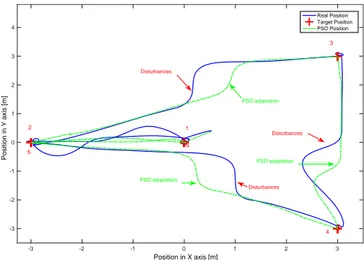
Figures 4 and 5 illustrate the adaptation of the generated path, taking into account the target’s position and cor-recting the disturbance.
Position in X axis [m] -3 -2 -1 0 1 2 3 Position in Y axis [m] -3 -2 -1 0 1 2 3 4 Real Position Target Position PSO Position 4 3 Disturbances PSO adaptation Disturbances PSO adaptation Disturbances PSO adaptation 1 6 5 2
Fig. 4. 2D representation of the given targets, the com-puted trajectory, and the UAV’s real position.
Time [s] 0 5 10 15 20 25 30 35 40 45 Position in X axis [m] -3 -2 -1 0 1 2 3 x Real x Target x PSO Time [s] 0 5 10 15 20 25 30 35 40 45 Position in Y axis [m] -3 -2 -1 0 1 2 3 y Real y Target y PSO
Fig. 5. Target reference, trajectory, and quadrotor’s po-sition for each axis, note the disturbances and the trajectory adjustments.
b) A second experiment was then introduced in which large perturbations are induced to the vehicle while it stays in hover mode (i.e. steady over a fixed target point).
Fig. 6. A member of our team inducing large perturbations on the quadrotor. Time [s] 0 10 20 30 40 50 60 70 80 Position in X axis [m] -1 0 1 2 3 4 x Realx Target x PSO Time [s] 0 10 20 30 40 50 60 70 80 Position in Y axis [m] -2 -1.5 -1 -0.5 0 0.5 1 1.5 2 2.5 y Real y Target y PSO PSO adaptation Disturbances PSO adaptation Disturbances
Fig. 7. Performance of the PSO trajectory generator to recover from large perturbations.
Figure 6 illustrates a member of our team displacing the drone to a position far from the desired reference (which was set to [0,0]) with one hand.
Observe on figure 7 that the PSO algorithm computes a trajectory to return to the reference target, but since it stays close to the UAV’s position, the recovery from the disturbance is smooth.
4.3 One agent in the presence of obstacles
In the next experiment, a barrier is considered to be across the path of the quadrotor. When the vehicle approaches near the obstacle, the PSO algorithm adapts the trajectory to avoid a collision, see Figure 8.
Position in X axis [m] -3 -2 -1 0 1 2 3 Position in Y axis [m] -1 -0.5 0 0.5 1 1.5 2 2.5 3 3.5 4 Real Position Target Position PSO Position Obstacle PSO adaptation
Fig. 8. Vehicle’s trajectory correction to avoid collision with an obstacle.
Figure 9 illustrates the generation of the trajectory for both x and y axes in the previous scenario, note the corrections made to the trajectory mainly in the y axis to avoid the obstacle.
Time [s] 0 1 2 3 4 5 6 7 8 Position in X axis [m] -3 -2 -1 0 1 2 3 x Real x Target x PSO Time [s] 0 1 2 3 4 5 6 7 8 Position in Y axis [m] 0 0.5 1 1.5 2 2.5 3 3.5 y Real y Target y PSO
Fig. 9. Target reference, trajectory generation, and vehi-cle’s position for obstacle avoidance experiments.
4.4 Fleet of three quadrotors
Finally, the PSO algorithm was applied in a fleet of UAVs consisting of three quadrotors in a simulated environment, see Figure 10.
In this simulation, the target point’s position Pd and the
desired configuration for the UAVs from the matrix ∂d are
fixed. The elements dij(t) are defines such that the desired
distance between UAVs is homogeneous, thus arriving to a triangle configuration around the target point.
Fig. 10. Simulated environment for fleet of three drones The simulated experiment consisted on a set of four reference points, given to each quadrotor using a ground station. Each quadrotor then computes independently its trajectory taking into account the position of the other agents.
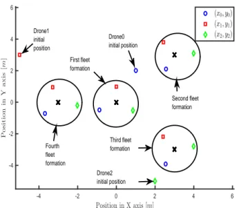
A first simulation consisted in initializing the quadrotors in random position, then a sequence of four target points are given at different times. The UAVs then form a fleet around the reference ensuring a safety distance between each other. Figure 11 represents this behavior.
Position in X axis [m] -4 -2 0 2 4 6 P o s it io n in Y a x is [m ] -4 -2 0 2 4 6 (x0, y0) (x1, y1) (x2, y2) Drone1 initial position First fleet formation Drone0 initial position Third fleet formation Drone2 initial position Second fleet formation Fourth fleet formation
Fig. 11. Fleet formation around each reference point on a flight simulations
A second simulation was then performed to illustrate the trajectory followed by each agent to arrive to the formation of the fleet. Figure 12 illustrates the path followed by each UAV.
Note the triangular formation of the fleet when the target is reached, and the agents reaction when they come close to each other. Position in X axis [m] -4 -2 0 2 4 6 P o s it io n in Y a x is [m ] -4 -2 0 2 4 6 (x0, y0) (x1, y1) (x2, y2) Target 4 Target 3 Target 1 Target 2
Fig. 12. A second simulation shows the trajectory followed by each UAV to converge to the desired formation An important issue that needs to be addressed in the fleet formation problem is convergence of the distance between agents to a desired value. In this case, an uniform triangular formation is expected with a desired distance of 1m towards the target, thus implying using simple
geometry that the distance between agents is dagents =
2(1m) cos(π/6) = 1.732m
Fig. 13. Desired distance between agents in a simulated experiment
Figure 13 illustrates the convergence of all the distances between agents to the desired value, thus ensuring the fleet formation around the target. It should be noticed that the safety distance of the neighborhood is respected throughout the simulation.
5. CONCLUSION
This paper has presented a distributed path planning approach for the control of a fleet of Unmanned Aerial Vehicles. The control objective has been formulated as an optimization problem based on a Particle Swarm Opti-mization algorithm (PSO). The miniOpti-mization of a cost function allowed to generate in a distributed way the trajectories of the UAVs which guarantee the control of the fleet. The main advantage of the proposed approach is
that it is only dependent on the trajectory generation part and it is independent from the model or from the control law of the UAVs, which makes it easier to use.
Simulation and experiment results have clearly shown that the proposed method is effective for the surface coverage and have also shown a robust approach against the collisions and obstacle avoidance. From those first results, we intend to develop this algorithm more in terms of formalization and implement it soon on control of fleet of real quadrotors in a 3D space. Another perspective would be to adapt the algorithm parameters to consider the case of a moving target.
REFERENCES
[1] GUERRERO, Jose et LOZANO, Rogelio (ed.). Flight
formation control. John Wiley Sons, 2012.
[2] CHIARAMONTI, Martina. Formation control laws
for autonomous flight vehicles. In : 2006 14th Mediter-ranean Conference on Control and Automation. 2006, ANCONA, ITALY. p. 1-5.
[3] OLFATI-SABER, Reza. Flocking for multi-agent
dy-namic systems: Algorithms and theory. IEEE Trans-actions on Automatic Control, ,2006, vol. 51, no 3, p. 401-420.
[4] PARK, Jaemann, KIM, H. Jin, and HA,
Seung-Yeal. Cucker-Smale flocking with inter-particle bond-ing forces. IEEE Transactions on Automatic Control, 2010, vol. 55, no 11, p. 2617-2623.
[5] LI, Zhongkui, DUAN, Zhisheng, CHEN, Guanrong, et
al. Consensus of multiagent systems and synchroniza-tion of complex networks: a unified viewpoint. IEEE Transactions on Circuits and Systems I: Regular Pa-pers, 2010, vol. 57, no 1, p. 213-224.
[6] SCHENATO, Luca et FIORENTIN, Federico.
Aver-age TimeSynch: A consensus-based protocol for clock synchronization in wireless sensor networks. Auto-matica, 2011, vol. 47, no 9, p. 1878-1886.
[7] CORTS, Jorge, MARTNEZ, Sonia, et BULLO,
Francesco. Robust rendezvous for mobile autonomous agents via proximity graphs in arbitrary dimensions. IEEE Transactions on Automatic Control, 2006, vol. 51, no 8, p. 1289-1298.
[8] SU, Housheng, WANG, Xiaofan, et CHEN,
Guan-rong. Rendezvous of multiple mobile agents with preserved network connectivity. Systems & Control Letters, 2010, vol. 59, no 5, p. 313-322.
[9] HUI, Qing. Finite-time rendezvous algorithms for
mobile autonomous agents. IEEE Transactions on Automatic Control, 2011, vol. 56, no 1, p. 207-211. [10] REYNOLDS, Craig W. Flocks, herds and schools: A
distributed behavioral model. ACM Siggraph Com-puter Graphics, 1987, vol. 21, no 4, p. 25-34.
[11] S. M. Ahn, H. Choi, S.-Y. Ha, and H. Lee. Oncollision-avoiding initial configurations to cucker-smale type flocking models. Communications in Mathematical Sciences, 2012, vol. 10, p. 625-643.
[12] PARK, Jaemann, KIM, H. Jin, and HA, Seung-Yeal. Cucker-Smale flocking with inter-particle bond-ing forces. IEEE Transactions on Automatic Control, 2010, vol. 55, no 11, p. 2617-2623.
[13] BELKADI, Adel, THEILLIOL, Didier,
CIAR-LETTA, Laurent, Ponsart, J. C. Robust flocking
con-trol design for a fleet of autonomous agents. In : 3rd Conference on Control and Fault-Tolerant Systems, SysTol 2016. 2016, Barcelona, Spain.
[14] NEDIC, Angelia et OZDAGLAR, Asuman. Dis-tributed subgradient methods for multi-agent opti-mization. IEEE Transactions on Automatic Control, 2009, vol. 54, no 1, p. 48-61.
[15] RABBAT, Michael et NOWAK, Robert. Distributed optimization in sensor networks. In : Proceedings of the 3rd international symposium on Information processing in sensor networks. ACM, p. 20-27. April 26 - 27, 2004, Berkeley, CA, USA
[16] MICHAEL, Nathan, ZAVLANOS, Michael M., KU-MAR, Vijay, et al. Distributed multi-robot task as-signment and formation control. In : Robotics and Automation, 2008. ICRA 2008. IEEE International Conference on. IEEE, 2008. p. 128-133. Pasadena, California
[17] BERMAN, Spring, HALASZ, Adam, HSIEH, M. Ani, et al. Optimized stochastic policies for task allocation in swarms of robots. IEEE Transactions on Robotics, 2009, vol. 25, no 4, p. 927-937.
[18] BELKADI, Adel, CIARLETTA, L., et THEILLIOL, D. UAVs team flight training based on a virtual leader: Application to a fleet of Quadrirotors. In : Unmanned Aircraft Systems (ICUAS), 2015 Inter-national Conference on. IEEE, 2015. p. 1364-1369. Denver Marriott Tech Center Denver, Colorado, USA [19] BELKADI, A., CIARLETTA, L., et THEILLIOL, D. UAVs fleet control design using distributed par-ticle swarm optimization: A leaderless approach. In : Unmanned Aircraft Systems (ICUAS), 2016 Interna-tional Conference on. IEEE, 2016. p. 364-371. Wash-ington, USA
[20] KENNEDY, James, KENNEDY, James F., EBER-HART, Russell C., et al.Swarm intelligence. Morgan Kaufmann, 2001.
[21] EBERHART, Russ C., KENNEDY, James, et al. A new optimizer using particle swarm theory. In : Proceedings of the sixth international symposium on micro machine and human science. 1995. p. 39-43. [22] GUO, Jinchao, WANG, Xinjin, et ZHENG, Xiaowan.
Trajectory planning of redundant robot manipulators using QPSO algorithm. In : Intelligent Control and Automation (WCICA), 2010 8th World Congress on. IEEE, 2010. p. 403-407. Jinan, China
[23] CHYAN, Goh Shyh et PONNAMBALAM, S. G. Obstacle avoidance control of redundant robots using variants of particle swarm optimization. Robotics and Computer-Integrated Manufacturing, 2012, vol. 28, no 2, p. 147-153.
[24] CARINO, Jossu, ABAUNZA, Hernan, et
CASTILLO, P. Quadrotor quaternion control.
In : Unmanned Aircraft Systems (ICUAS), 2015 International Conference on. IEEE, 2015. p. 825-831. Denver Marriott Tech Center Denver, Colorado, USA