READ THESE TERMS AND CONDITIONS CAREFULLY BEFORE USING THIS WEBSITE. https://nrc-publications.canada.ca/eng/copyright
Vous avez des questions? Nous pouvons vous aider. Pour communiquer directement avec un auteur, consultez la première page de la revue dans laquelle son article a été publié afin de trouver ses coordonnées. Si vous n’arrivez pas à les repérer, communiquez avec nous à [email protected].
Questions? Contact the NRC Publications Archive team at
[email protected]. If you wish to email the authors directly, please see the first page of the publication for their contact information.
NRC Publications Archive
Archives des publications du CNRC
This publication could be one of several versions: author’s original, accepted manuscript or the publisher’s version. / La version de cette publication peut être l’une des suivantes : la version prépublication de l’auteur, la version acceptée du manuscrit ou la version de l’éditeur.
Access and use of this website and the material on it are subject to the Terms and Conditions set forth at
Overview of recent progress in fire suppression technology
Kim, A. K.
https://publications-cnrc.canada.ca/fra/droits
L’accès à ce site Web et l’utilisation de son contenu sont assujettis aux conditions présentées dans le site LISEZ CES CONDITIONS ATTENTIVEMENT AVANT D’UTILISER CE SITE WEB.
NRC Publications Record / Notice d'Archives des publications de CNRC:
https://nrc-publications.canada.ca/eng/view/object/?id=bfbb4c0d-8212-4191-b935-c2af268b99a5 https://publications-cnrc.canada.ca/fra/voir/objet/?id=bfbb4c0d-8212-4191-b935-c2af268b99a5
Overview of recent progress in fire suppression
technology
Kim, A.
A version of this document is published in / Une version de ce document se trouve dans :
Invited Keynote Lecture at the 2nd NRIFD Symposium, Proceedings, Tokyo, Japan, July 17-19, 2002, pp. 1-13
www.nrc.ca/irc/ircpubs
NRCC-45690
Title: OVERVIEW OF RECENT PROGRESS IN FIRE
SUPPRESSION TECHNOLOGY
Author(s): Andrew KIM
Corresponding (first) author: Andrew Kim
Academic degree: Ph.D.
Position: Senior Research Officer
Professional or Academic affiliation: National Research Council of Canada
Mailing address: National Research Council, Institute for Research in Construction,
1200 Montreal Road, Bldg. M-59, Ottawa, Ontario, Canada, K1A 0R6
Phone: (613) 993-9555
Fax: (613) 954-0483
OVERVIEW OF RECENT PROGRESS IN FIRE SUPPRESSION TECHNOLOGY
Andrew KIM1
SUMMARY
In recent years, with the halon phase-out, there has been a major thrust towards finding new advanced fire suppression systems. Some of the newly developed fire suppression systems include halocarbon and inert gaseous agents, water mist systems, compressed-air-foam systems, and aerosol and gas generators.
Halocarbon agents are chemicals similar to halon except that its molecular structure was modified to reduce or eliminate the chlorine and bromine atoms that are responsible for ozone depletion. They can extinguish fires at their design concentration, however, they produce Thermal Decomposition Products (TDP) including hydrogen fluoride (HF) at much higher levels than halon.
Inert gas agents extinguish fire by oxygen depletion. They have zero ODP and no Global Warming potential, and they are not subject to thermal decomposition when used in extinguishing fires. However, they require high-pressure storage cylinders which has implications for space and weight.
Fire suppression by water mist is mainly by a physical mechanism. Water mist fire suppression systems have demonstrated a number of advantages, such as good fire suppression capability, no environmental impact and no toxicity. However, water mist does not behave like a total flooding agent, thus the fire suppression effectiveness of water mist depends on the potential size of the fire, properties of the combustibles, and the degree of obstruction, as well as the water mist characteristics.
Aerosol systems produce micron size dry chemical particles and gas products, and extinguish fires by removing and recombining flame propagation radicals and by absorbing heat. Gas generators produce a large quantity of inert gases by combustion of solid propellants , and extinguish fires by oxygen depletion.
All of the recently developed fire suppression systems extinguish fires at their design conditions, however, no one system can be chosen as the best system for all applications. Some perform better than others in a particular application. All have some limitations and concerns that have to be dealt with in extinguishing fires.
1
Suppressing fire by throwing water onto it has been used since ancient times. To provide automatic spray of water in case of fire, automatic sprinkler system was developed at the turn of the century. Since then, sprinkler system has been used widely as the most common fixed fire suppression system in providing fire safety in buildings. However, water is not a suitable suppression medium for all types of fires. Water, when sprayed in coarse droplets such as in sprinkler spray, is not effective in suppressing liquid fuel fires. Also, in some cases, water damage is a concern because of the large amount of water used in sprinkler activation.
Other types of fire suppression agents that has been used for long time are dry chemical powders and CO2. Dry
chemical is typically used as a manual application with extinguishers.
In the 1940’s, halon chemicals were developed as a superior performing suppression agent. Because of its low cost and superior fire suppression performance, halon was the agent of choice and was used widely, including in applications where halon is not necessarily the only option. This inhibited development of other fire suppression technologies that had good potential. Recently, because of halon phase-out due to environmental reasons, there was a major thrust to develop new fire suppression technologies that are effective and also environmentally friendly.
This paper gives a brief overview of the newly developed fire suppression systems, and provides technical information on the fire suppression performance of each system as well as the limitations or concerns related to using the new suppression systems.
2. HALON PHASE-OUT
In the 1940’s, an effort was made to develop a more effective fire suppression agent than the ones being used at that time. The first systematic search for effective gaseous fire suppressants can be traced to the late 1940s when the Purdue Research Foundation conducted an extensive study of more than 60 chemical compounds for the U.S. army [Purdue University, 1950]. This study led to the development of halon chemicals as a superior performing suppression agent. Halon is a chemical agent, which combines hydrogen, carbon, chlorine and bromine atoms. The chlorine and bromine component in the halon chemical reacts with the O-H radicals produced during combustion to inhibit the combustion reaction.
Halons are excellent fire suppressants, however, they contribute significantly to stratospheric ozone depletion. Fire protection halons were phased out of production in developed countries due to an international consensus to regulate the use of ozone-depleting substances (ODSs) as reflected in the Montreal Protocol (1987, London Amendments 1990, Copenhagen Amendments 1992). There is a major thrust, therefore, to find an appropriate fire suppression agent to replace halon.
The present challenge is to find halon substitutes that have sufficient fire suppression ability for various applications without harming the environment and human health. There has , in recent years, been extensive research to develop halon replacements and alternatives.
Halon replacements are gaseous agents with similar physical properties and fire extinguishing mechanisms as halon. Most research effort for halon replacements has been directed toward modifying the molecular structure of halons to reduce or eliminate the chlorine and bromine atoms which are responsible for ozone depletion. This category of halon-like halocarbons includes perfluorocarbons (PFCs or FCs), hydrofluorocarbons (HFCs), hydrochlorofluorocarbons (HCFCs), hydrobromofluorocarbons (HBFCs), and fluoroiodocarbons (FICs) [Senecal, 1992].
Possible alternatives to halons include both long established technologies and new concepts or agents that have emerged recently. Traditional fire protection systems include automatic sprinkler, dry chemical, carbon dioxide, and foam systems. These traditional fire suppression systems perform well in specific applications. However, they are not sufficiently effective in other applications to replace the use of halon.
To satisfy this need, several new fire suppression systems have been developed or old approaches have gained renewed interest. Most attention has been focused on inert and halocarbon gaseous systems, water mist systems, compressed-air-foam systems, and solid gas and aerosol generators.
3. GASEOUS SYSTEMS
Total flooding gaseous systems use nozzles, pipes and pressurized cylinders to discharge the gas into an enclosed space. The enclosure must be capable of holding the gas and coping with the pressure of the gas discharge. There are two types of gaseous agents available: inert gases and halocarbon agents.
3.1 Halocarbon Agents
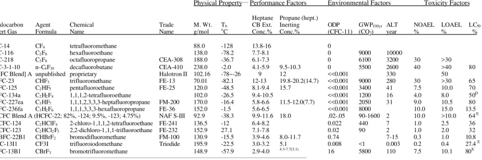
Halocarbon agents are chemicals similar to halon except their molecular structure has been modified to reduce or eliminate the chlorine and bromine atoms that are responsible for ozone depletion. Halocarbon agents extinguish fires primarily by cooling. Some of the halocarbon chemicals, which have been tested recently, are listed in Table 1 with their physical properties, environmental impacts, toxicity and fire suppression efficiency factors. Most of the information on halocarbon agents in this paper was previously published in the Journal of Fire Protection Engineering [Su et al., 1996].
Fire suppression performance of the halocarbon agents are primarily evaluated using small-scale tests. The most widely accepted technique for laboratory screening of fire suppression agents to determine its fire suppression effectiveness is the cup burner method. A cup burner consists of a fuel cup inside a chimney. Liquid fuel is gravity fed to the cup from a reservoir and maintained at the cup edge level. After ignition and stabilization of the diffusion flame on the cup, the agent is gradually added into the chimney through an agent/air mixture supply system until the liquid pool flame is extinguished. The corresponding concentration of the agent in the mixture is referred to as the cup burner flame extinguishing concentration for that agent [NFPA 2001, 2000].
Table 1 lists the agents' concentrations for extinguishing heptane cup-burner flames. It should be pointed out that the cup burner value for the same agent may be different for other fuels. Regardless of fuel types, however, most agents listed in the table have higher extinguishing concentrations in the cup burner tests than Halon 1301 and, therefore, are considered to be less effective.
For fire suppression agents, two toxicological aspects must be considered. One is the toxicity of the agent itself, and the other is the toxicity of combustion reaction products of the agent produced under fire conditions. Acceptability of an agent by regulatory authorities is mostly determined by the agent toxicity.
Inhalation of halocarbons and hydrocarbons can cause the heart to be abnormally sensitive to elevated adrenaline levels, and can lead to cardiac arrhythmia and possibly heart attack. Cardiotoxicity tests are usually conducted using beagle dogs to determine the potential of an agent to cause cardiac sensitization. The results are provided as “no observed adverse effect level” (NOAEL) and “lowest observed adverse effect level” (LOAEL), as shown in Table 1. Since cardiac sensitization is the toxic effect that occurs at the lowest concentration, the US Environmental Protection Agency (EPA) compares the cardiac NOAEL and LOAEL of halocarbon agent with its extinguishing concentration to determine whether the agent is acceptable for total flooding applications in occupied spaces. Among the halocarbon chemicals listed in Table 1, several agents have come to the fore, namely FM-200 (HFC-227ea), FE-13 (HFC-23), FE-36 (HFC-236fa), NAF S-III (HCFC blend), and CEA-410 (FC-3-1-10). These five agents have several common characteristics; they are stored as liquefied gases in cylinders, and they are clean agents, leaving no residue after discharge and are electrically non-conductive. Also, as Table 1 shows, these five gaseous agents have NOAEL values higher than the extinguishing concentration, acquiring listing under the Significant New Alternatives Policy (SNAP) program of US EPA for use in occupied space.
The extinguishing concentrations of gaseous agents are determined by small-scale tests. However, several research laboratories have conducted intermediate and full-scale fire suppression tests to evaluate the true fire suppression performance of these agents.
Intermediate-scale fire suppression tests, coupled with real-time FTIR measurements for agent and acid gas products, were conducted by University of New Mexico Engineering Research Institute (NMERI) using an 18.3 m3
chamber to evaluate HFC-23, HFC-227ea, FC-3-1-10 and HCFC Blend A [Moore et al., 1993]. Fire scenarios included Class A wood crib fires, Class B heptane pool fires and diesel spray fires.
The heptane pool fire tests revealed no substantial differences in fire suppression performance among the four agents. In order to minimize the amount of acid gas products, agent concentrations of cup burner values + 40% and 5 s discharge times were required to extinguish the fires within 7 s (for HCFC Blend A, a concentration of 12% was used). Even under such conditions, the four agents produced at least 10 times higher HF concentrations than Halon 1301. HFC-23 and HCFC Blend A produced more HF than the other two agents, and also produced significant amounts of COF2.
In general, the concentrations of the acid gas products depend on the extinction time and fire size. In addition, the distribution of the agent was shown to be a significant factor affecting its fire suppression performance.
The US Naval Research Laboratory (NRL) performed a series of intermediate-scale and full-scale tests with HFC-23, HFC-227ea and FC-3-1-10 to evaluate the effect of their discharge characteristics and distribution on fire suppression effectiveness. The intermediate-scale tests were conducted in NRL’s 56 m3 compartment [Sheinson et al., 1994a]. The three agents extinguished the test fires at the design concentrations. However, the tests indicated a 10-fold increase in HF production for these agents compared to that from Halon 1301.
Increasing the agent concentrations generally led to faster extinguishment and lower HF production for the same discharge time. However, HF production was not sensitive to agent concentrations above cup burner + 75%. Similarly, faster discharge resulted in faster extinguishment and lower HF production at the same design concentration.
The NRL’s full-scale tests with HFC-23 and HFC-227ea were conducted aboard the Ex-USS SHADWELL in Mobile Bay, Alabama [Sheinson et al., 1994b, 1994c]. Four test series were carried out in an 843 m3 machinery space.
Fire suppression tests were conducted using design concentrations of 8.2%, 9.2% and 10% for HFC-227ea and of 16% and 18% for HFC-23 with a 10 s discharge time (one test achieved a 6 s discharge time). All fires were suppressed successfully within 28 s for each test scenario, but re-flashes and sustained re-ignitions occurred in several tests. Peak HF concentrations were 2400-7300 ppm, about 4-12 times those of the Halon 1301 baseline tests. The full-scale test results are similar to those from the intermediate-scale test: extinguishment time and HF concentration decrease with increasing agent concentration and with decreasing discharge time; a larger fire is easier to extinguish (but produces more HF) than a smaller one.
The U.S. Coast Guard conducted a series of full-scale (560 m3) tests in a machinery space on a test ship located in Mobile, Alabama [Hansen et al., 1994]. Test agents included HFC-23, HFC-227ea, FC-3-1-10 and HCFC Blend A at the design concentrations recommended by their manufacturers. The performance of the agents was evaluated using three test scenarios: a 500 kW heptane spray fire with a 500 kW heptane pan fire, a 2 MW heptane spray fire with a 500 kW heptane pan fire, and a 5 MW diesel pan fire with a 500 kW PVC cable fire.
It was reported that HFC-23, HFC-227ea and FC-3-1-10 extinguished all test fires within 22 s, while HCFC Blend A required more than 1 min to extinguish the test fires due to the low design concentration of 8.6% and “problems associated with achieving this design concentration”. The measured HF production from HFC-23, HFC-227ea and FC-3-1-10 was 5-10 times that of Halon 1301, while the HCFC Blend A produced about 40 times more HF than Halon 1301. These full-scale tests also indicated that faster discharge and higher design concentrations of the agents can result in earlier fire extinguishment and less HF production.
The National Research Council of Canada (NRC) carried out full-scale fire suppression testing of HFC-227ea and HCFC Blend A in a 121 m3 compartment [Kim and Su, 1999]. HFC-227ea was tested at concentrations of 7.6 and 8.8%, and HCFC Blend A was tested at concentrations in the range of 8.6 - 14%. The test results showed that HCFC Blend A, at a design concentration of less than 10%, was not successful in extinguishing all fires. HFC-227ea, at a design concentration of 7.6% or higher, and HCFC Blend A, at a design concentration of 12%, extinguished all test fires. HF and COF2 were produced during fire suppression tests with HFC-227ea and HCFC
increased with increasing fire sizes and discharge times and decreased with increasing agent concentrations. The concentrations of HF and HCl produced during the HFC-227ea and HCFC Blend A tests were much higher than the Halon 1301 test. The test results also showed that an increased quantity of carbon monoxide was produced during fire suppression tests with HCFC Blend A and HFC-227ea, caused by agent-flame interaction.
Test data from small-scale to full-scale have shown that the halocarbon replacements extinguish fires at their design concentrations. However, the design concentrations of the halocarbon agents are much higher than Halon-1301, resulting in volume and weight penalties. The test data also show that the current halocarbon agents produce at least 5-10 times more HF and COF2 than Halon 1301 during fire suppression. The HF and COF2 levels produced in the
test fires were significantly higher than all human exposure limits. The level of HF and COF2 production during fire
extinguishment depend on many factors such as agent type and concentration, fire type and size, and discharge and extinguishment times. The NRC tests [Kim and Su, 1999] also indicate that halocarbon agents produce CO during fire extinguishment, which could be another safety issue.
Some of the halocarbon agents have long Atmospheric Life Time and they could make long-term contribution to global warming if emitted to the atmosphere. The green house effect has now become an environment concern, and will become a determining factor in selecting suitable suppression agents in the future.
3.2 Inert Gas Agents
Inert gas agents are total flooding agents and extinguish fire by oxygen depletion. When they are discharged into a compartment to extinguish fire, they displace oxygen in the compartment and lower the oxygen concentration around the fire, eventually to a level below the concentration, which will support the combustion. These inert gases, such as nitrogen, argon and helium, are clean and naturally occurring in the atmosphere. They have zero Ozone Depletion Potential (ODP) and no Global Warming potential. Also, inert gases are not subject to thermal decomposition when used in extinguishing fires, and hence form no combustion by-products.
To suppress a fire, a sufficient volume of inert gas must be injected into the enclosure to reduce the oxygen content to a level at which combustion cannot be maintained. This is generally considered to be about 14.3%. In order to provide an adequate safety factor, the normal objective is to reduce the oxygen level to about 12.5%. This requires a concentration of about 40% of the inerting gas in the enclosure.
Currently, there are 3 inert gas systems that are commercially available: Argonite (IG-55) which is a mixture of 50% nitrogen and 50% argon, Inergen (IG-541) which is a mixture of 52% nitrogen, 40% argon and 8% carbon dioxide, and Argon (IG-01) which is 100% argon.
The three agents are similar in fire suppression performance, but the addition of a small percentage of carbon dioxide in Inergen induces a higher breathing rate, which enables people to continue to function unimpaired by effects of oxygen depletion for a reasonable period of time (tested to 30 min with human volunteers). This demonstrates that there is little hazard to personnel in a ‘no-fire’ situation and probably confers a small benefit over the other inerting gases in such situations. In a real fire however, the benefit may be reduced as the inhalation of combustion products must be taken into account.
Inert gases are not liquefied gases. They are stored as high pressure gases and hence require high pressure storage cylinders which has implications for space and weight. Also, inert gases will require a system that is sufficiently robust to withstand the pressures involved.
4. WATER MIST FIRE SUPPRESSION SYSTEM
The term "water mist" refers to fine water sprays in which 99% of the volume of the spray is in drops with diameters less than 1000 microns. The study and description of the fundamental principles of extinguishment of liquid and solid fuel fires by water mist can be traced back to the mid-1950s [Braidech et al., 1955]. Research continued to be carried out during the 1960s and 1970s at university, industry and government research facilities. These early studies [Braidech et al., 1955, Rasbash et al., 1960] focused on the extinguishing mechanisms of water mist and the optimum droplet parameters for efficient fire suppression. At the same time, however, Halon 1301 and 1211, the
most effective chemical fire suppressants, were introduced. The application of water mist to fire suppression was, therefore, not considered practical until the recent requirement to phase out halon agents due to their negative environmental effects.
Over the last decade, studies on water mist technology have significantly increased. A survey carried out by Mawhinney and Richardson [Mawhinney and Richardson, 1997] in 1996 indicated that nearly 50 agencies around the world are involved in the research and development of water mist fire suppression systems, ranging from theoretical investigations into extinguishing mechanisms and computer modelling to the development, patenting and manufacturing of mist-generating equipment. These recent studies have shown that water mist technologies have the potential either to replace current fire protection techniques that are no longer environmentally acceptable, or to provide new answers to problems where traditional technologies have not been as effective as desired. Their efficacy for fire protection has been demonstrated in a wide range of applications and by numerous experimental programs. Water mist in fire suppression, however, does not behave like a “true” gaseous agent, and is substantially affected by the fire size, the degree of obstruction, ceiling height and the ventilation conditions in the compartment. Fire suppression by water mist is mainly by a physical mechanism and no significant chemical effects are involved. The early studies [Braidech et al., 1955, Rasbash et al., 1960] identified flame cooling and oxygen displacement as the dominant mechanisms in water mist fire suppression. Recent investigations, however, suggested that there are additional mechanisms in water mist fire suppression [Wighus, 1995, Mawhinney et al., 1994]. One such mechanism is the radiation attenuation provided by water mist which can stop the fire from spreading to an un-ignited fuel surface and reduces the vaporization or pyrolysis rate at the fuel surface. Tests conducted at NRC [Mawhinney et al., 1994] showed that the radiant heat flux to the walls of the test compartment was reduced by more than 70 percent by the water mist. Other extinguishing mechanisms, considered as secondary, include dilution of flammable vapors, and direct impingement wetting and cooling of the combustibles.
Water mist characteristics, such as drop size distribution, flux density and spray momentum, have a direct effect on its fire suppression effectiveness. To effectively suppress a fire, a water mist system must generate and deliver optimum sized droplets with an adequate concentration to the fire. The selection of the optimum size of droplets for fire suppression is dependent on the potential size of the fire, properties of the combustibles, and the degree of obstruction and ventilation in the compartment. There is no one drop size distribution to fit all fire scenarios.
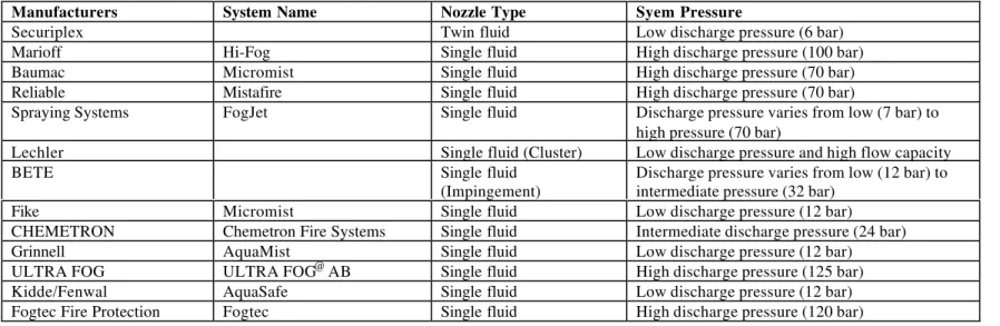
Currently, there are several water mist systems available commercially. Some are using high or intermediate pressures of water through small orifices of nozzle to produce water mist whereas others are using twin fluid nozzles (water and air). Some of the commercial water mist systems are listed in Table 2. Water mist fire suppression systems have demonstrated a number of advantages, such as good fire suppression capability, no environmental impact and no toxicity. As a result, the use of water mist as a fire suppression system has been considered in a wide range of practical applications.
One application in which water mist was shown to have considerable potential for fire suppression was in shipboard machinery spaces. NRC and other research agencies have conducted many full-scale tests to evaluate the fire suppression performance of water mist systems in such spaces. These tests [Mawhinney, 1994, Darwin et al., 1995, Buckley and Rush, 1996] showed that water mist systems can effectively extinguish large fires in unventilated machinery spaces using a small amount of water. The performance was comparable to that of gaseous halon replacements.
Water mist systems were able to extinguish a wide variety of fires when natural ventilation such as open doors and hatches were allowed, while gaseous agents were not effective under such conditions. Water mist systems also rapidly reduced the compartment temperature and significantly improved visibility. This would allow accessibility to the compartment during fire suppression.
Another area where water mist has a potential as an effective halon alternative is the protection of electronic equipment. However, the telecommunications and utilities industries have traditionally been reluctant to use water as a fire suppressant on electrical and electronic equipment because of concerns about potential water damage. A preliminary study [Hills et al., 1993] to determine the feasibility of using a water mist system to suppress in-cabinet electronic fires showed that the fine water mist was effective in extinguishing fires without causing short circuits or other damage to electrical and electronic components.
NRC has carried out a project to study the feasibility of using water mist as an alternative to gaseous agents to protect facilities with substantial amounts of electronic equipment [Mawhinney, 1996]. As a part of this project, a series of full-scale fire suppression tests were conducted using water mist in electronic cabinets, under-floor cable plenums and overhead cable trays. The experimental investigations demonstrated that the traditional total-flooding approach (used for Halon 1301), was unreliable when applied to water mist. On the other hand, reliable fire suppression was achieved with water mist by exercising rigorous control over spray direction to the hazard. This was accomplished by laying out the nozzles to suit the physical arrangement of the obstructions or structural elements. The studies also showed that coarser sprays (200<Dv0.9<400 microns) which produced wetting of surfaces
and water dripping down into recessed places, had better performance than very fine sprays (Dv0.9<90 microns)
against fires in electronic equipment. The investigations also showed that a water mist system can be used to suppress fires in electrical and electronic equipment with minimum water damage.
A potential advantage of water mist is that the damage to the electronic equipment could be far less than the damage caused by thermal decomposition products of gaseous halon replacement agents. A recent study [Kim and Su, 1999] with halocarbon gaseous agents indicated that when they are applied to a smoldering electrical fire, the gaseous agents can decompose and produce high concentrations of corrosive gases such as HF. Also with gaseous agents, the compartment has to be evacuated completely during the agent discharge, disabling the operation of the room. However, with water mist, the evacuation of the compartment may not be necessary, especially if a zoned water mist system is used. This may allow a continuation of limited operation in the compartment when such operation is critical in carrying out a mission.
Another recent NRC study [Kim et al., 1999] has shown that the fire suppression performance of water mist can be further improved by using a cycling discharge. The cycling discharge mode involves a continuous alternation of the On and Off cycle of the water mist discharge. The study clearly indicated that the fire extinguishing performance of the water mist system was substantially increased when a cycling discharge mode was used instead of a continuous discharge. When a fire challenge was small, the water mist system easily extinguished the fire, thus the improvement with the cycling discharge was small. However, even under those conditions, the amount of water required to extinguish the fire was reduced by using the cycling discharge. For more challenging conditions, such as small fires and ventilated conditions, the use of a cycling discharge significantly reduced extinguishment times and the water requirements. When a cycling discharge was used, more water vapour and combustion products were produced during the test, which increased the rate of oxygen depletion in the test compartment. In addition, the recurrent dynamic mixing created by cycling discharge effectively dilutes the oxygen and fuel vapour available for the fire.
5. COMPRESSED-AIR-FOAM SYSTEM
For decades, fire-fighting foams delivered from fixed-pipe systems have provided effective fire suppression for applications in the chemical and petroleum industries and military installations. The overall effectiveness of current fixed pipe foam systems, which incorporate aspirating-type nozzles and blower-type foam generators, is limited since they are unable to provide foams with high injection velocity. Also, the foam produced using traditional systems is not as stable and consistent, and expansion ratios are not as high as would be desired for some applications, because the air to generate foam at the nozzle, which comes from the fire environment, may be contaminated. However, if compressed air is used for foam generation, the resulting foam possesses superior quality and substantial injection velocity, as well as requiring much lower quantity of water and foam concentrates.
Compressed-air-foam (CAF) is generated by injecting air under pressure into a foam solution stream. The process of moving the solution and air mixture through the hose or piping, if done correctly, forms a foam. The energy for the CAF comes from the combined momentum of the foam solution and air. One significant advantage of such systems is the increased momentum of the foam, enabling it to penetrate fire plumes and reach the seat of the fire. Another advantage of CAF is that it possess better stability with respect to drainage than aspirated foams, since it is characterized by a narrow distribution of bubble sizes.
Until now, attempts to adapt CAF to fixed installations have failed due to two fundamental technical difficulties : first, traditional sprinkler-type nozzles cannot distribute compressed air foam without collapsing it, and secondly, the
foam itself degenerates in fixed piping. Recently, NRC has overcome these difficulties, and developed a means of producing Class A and Class B CAF in a fixed pipe system, using a new and innovative foam distribution nozzle [Crampton et al., 1999]. Foam break-up, which prevented the development of this technology in the past, was avoided by the careful engineering design of the nozzle and the piping system.
An effective CAF system produces foam consisting of similar-in-size bubbles, delivers the foam to nozzles without changes in foam properties, and provides a means of uniformly distributing foams over a prescribed area. NRC’s fixed pipe CAF system consists of three zones: Air injection zone, Development zone and Discharge zone. In the air injection zone, air is injected into a stream of foam solution; in the development zone, foam solution and air flow through a segment of tubing, which acts as a foam improver and; in the discharge zone, foam is distributed over a wide area without loosing its momentum. To permit the smooth discharge of foam, a special nozzle was designed that provides a uniform distribution over the target area.
A series of full-scale fire tests were conducted to evaluate the performance of a prototype CAF system [Kim and Dlugogorski, 1997]. The fire scenarios used were 0.9 m diameter heptane and diesel pool fires and 0.6 m x 0.6 m x 0.3 m wood crib fire. The tests demonstrated the superior performance of CAF system in extinguishing both the liquid fuel and wood crib fires with a small amount of water. Also, CAF requires a smaller amount of foam concentrate to provide effective suppression, compared to systems based on air-aspirated nozzles. In the NRC tests, 0.3% Class A and 1% Class B foam solutions were used without compromising the extinguishment efficiency of compressed-air foams, compared to 1% Class A and 6% Class B foam solutions normally recommended for aspirated systems.
Recently, NRC developed a prototype CAF system [Kim and Crampton, 2001] for practical application in providing fire protection to a very large space such as aircraft hangar. Full-scale fire experiments of the prototype CAF system proved the superior performance of the CAF system in extinguishing simulated fuel spill fire in a aircraft hangar situation.
The research clearly demonstrated that fixed pipe CAF systems have a bright future, and an NRC licensee is currently developing a pre-engineered CAF system for a variety of commercial applications.
6. AEROSOL AND GAS GENERATORS
Information on the fire and explosion suppression of aerosol and gas generators are obtained from the previously reported work [Su and Kim, 2001]. The term ‘aerosol’ refers to a system of liquid or solid particles suspended in a gaseous medium. Fire extinguishing aerosols are usually created via a combustion process and delivered to the protected space either directly (on contact with the fire) or via devices located outside the protected volume.
Commercial aerosol systems are available for fire suppression in unoccupied spaces [Berezovsky and Joukov, 1999]. It contains solid rocket fuel, and when electrically or thermally ignited, the aerosol-forming composition produces dry chemical particles (K2CO3, KHCO3) and gas products (CO2, N2, H2O), and they are discharged through
end-plate delivery nozzles. The canister contains a polymer coolant, which absorbs heat before the hot aerosol leaves the nozzle. The solid particles are less than 1 micron in size, thus remaining suspended in the air for long periods of time. Suppression is achieved by removing combustion radicals (O, H, OH) and by absorbing heat. The ability of the aerosol to remain suspended for long periods of time and to fill and inert a volume, is an important factor.
Based on automotive airbag technology, gas generators have been developed for fire suppression applications [Wierenga and Holland, 1999]. Gas generators can produce a large quantity of gases (mainly N2, CO2 and H2O
vapour) by combustion of solid propellants . Solid propellants consist of oxidizers and fuel ingredients, and are able to burn without ambient air. Gas generators can be very compact and can provide very fast discharge (in a few milliseconds). Currently, there are two types of gas generators available: conventional gas generators and hybrid gas generators.
Conventional gas generators contain propellant and electrical initiator. When a signal was received from a detector/controller. the electrical initiator ignites a charge to start a combustion process of the propellant. Rapid
combustion of the solid propellants generates large amount of N2, CO2 and H2O vapour, which increases the internal
pressure rapidly. The hermetic seal is ruptured and the gas products are discharged in milliseconds to the protected space. The suppression action is by oxygen displacement and gas discharge dynamics.
The gases generated by the conventional gas generators are generally very hot (as high as 500°C) [Mitchell, 1999]. Since fire suppression applications require significantly lower exhaust gas temperatures, there have been efforts to develop cooler propellant formulations in order to reduce overall combustion temperature [Fallis et al., 2000]. Also, developing new propellant formulations with chemical additives was studied [Fallis et al., 2000].
A hybrid gas generator consists of an electrical initiator, a solid propellant chamber and a suppression agent chamber. The heat and pressure generated by the combustion of the propellant are used to heat and expel the liquefied suppressant. There are two types of hybrid gas generators available: in one type, the propellant chamber and the agent chamber are separated by a piston [Hagge et al., 1998]. As the propellant combustion takes place, pressure builds up in the propellant chamber and pushes the piston to pressurize the agent chamber. At a certain pressure, the propellant and the agent release disks are simultaneously ruptured releasing both the propellant gas and suppression agent into a mixing chamber. The mixture of propellant gas and suppression agent is discharged through a nozzle. In another type, propellant combustion products are directly released into the agent chamber to pressurize and discharge the agent [Mitchell, 1999, Lu and Wierenga, 2000]. Typically, liquid suppression agents used in hybrid gas generators are water, carbon dioxide, and halocarbon agents (HFC-227ea and PFC-514) [Lu and Wierenga, 2000].
7. STANDARDIZATION
With the introduction of new fire suppression technologies, there was a need to establish standards to address the limitations and the proper use of the newly developed fire suppression systems. Two standards stand out as an example of typical standard that were developed to meet the needs of the new fire suppression systems that were introduced: NFPA 2001 “Standard on Clean Agent Fire Extinguishing Systems” and NFPA 750 “Standard on Water Mist Fire Protection Systems”. Both are published by National Fire Protection Association (NFPA) in USA. NFPA standards are developed through a consensus standards development process. This process brings together volunteers representing varied viewpoints and interests to achieve consensus on fire and other safety issues.
NFPA 2001 “Clean Agent Standard” deals with gaseous halon replacement systems including halocarbon agents and inert gas systems. NFPA 2001 was established to address the needs on how to design, install, maintain and operate systems using the new clean agents that are being developed to replace Halon 1301. In 1991, the Technical Committee on Alternative Protection Options to Halon was organized and they started to prepare the NFPA 2001. The committee consisted of representatives from various interest groups who deals with the clean agents, such as manufactures, research laboratories, users, and testing/listing laboratories. The first edition of NFPA 2001 was published in 1994.
The standard is not a design handbook, but is prepared for the use and guidance to those dealing with clean agent extinguishing systems, so that such equipment will function as intended throughout its life. The standard contains information on the use and limitations of clean agents, such as the physical properties of halocarbon and inert agents, the maximum concentration allowed for the agents, formula for the amount of agent to achieve certain concentration in the compartment, and toxicity of the agent. Also, the standard deals with system components and hardware, system design, inspection, maintenance, testing and training.
NFPA 750 “Water Mist Standard” deals with water mist fire protection systems. In 1993, the NFPA Technical Committee on Water Mist Fire Suppression Systems was organized with representatives from the research and engineering communities, water mist system manufacturers, the insurance industry, enforcement authorities, and industrial users. The committee started to work on the development of a new NFPA document that would standardize water mist technology. In developing this standard, the committee addressed system components and hardware, system types, installation requirements, design objectives, hazard classifications, calculations, water supplies, atomizing media, plans, documentation, acceptance criteria, and maintenance considerations. The first edition of NFPA 750 was published in 1996.
The purpose of the NFPA 750 standard is to provide protection from fire through the standardization of design, installation, maintenance, and testing requirements of water mist fire suppression system. The standard covers the minimum requirements for the design, installation, maintenance, and testing of water mist fire protection systems, however, it does not provide definitive fire performance criteria nor does it offer specific guidance on how to design a system to suppress a fire.
Current edition of NFPA 750 was published in 2000, and it contains the new definition for water mist, design objectives and fire test protocols, guidance for the measurement of the water mist spray characteristics including drop distribution, and appendixes to address many of the current and proposed fire test protocols and the reliability of water mist systems.
8. ACKNOWLEDGEMENTS
The contribution of Dr. Joseph Su, Dr. Zhigang Liu, Mr. George Crampton and Dr. M. Kanabus-Kaminska of Fire Risk Management Program of National Research Council Canada (NRC) in carrying out the fire suppression research at NRC is gratefully acknowledged. The Department of National Defence Canada is also gratefully acknowledged for their financial support of the fire suppression research at NRC.
9. REFERENCES
Berezovsky, J. and Joukov, S. (1999), "PyroGen Fire Suppression Grenades," Proceedings of Halon Options
Technical Working Conference, Albuquerque, NM, p. 480.
Braidech, M.M., Neale, J.A., Matson, A.F. and Dufour, R.E. (1955), "The Mechanisms of Extinguishment of Fire by Finely Divided Water", Underwriters Laboratories Inc. for the National Board of Fire Underwriters, NY, 73p. Buckley, C. and Rush, D. (1996), "Water Mist Developments for the Royal Navy", Proceedings of Halon Options
Technical Working Conference, Albuquerque, NM, p. 37.
Crampton, G.P., Kim, A.K. and Richardson, J.K. (1999), “A New Fire Suppression Technology”, NFPA Journal, Vol. 93, No. 4, National Fire Protection Association, Quincy, MA.
Darwin, R.L., Leonard, J.T. and Back, G.G. (1995), "Development of Water Mist Systems for US Navy Shipboard Machinery Spaces", Proceedings of Halon Options Technical Working Conference, Albuquerque, NM, p. 411. Fallis, S., Reed, R., Lu, Y.-C.(F.), Wierenga, P.H. and Holland, G.F. (2000), "Advanced Propellant/Additive Development for Fire Suppressing Gas Generators", Proceedings of Halon Options Technical Working Conference, Albuquerque, NM, p. 361.
Hagge, H.B., Sears, R.F., Gschwind, D. and Black, R.E. (1998), "Pyrotechnically Augmented Liquid Agent System", Proceedings of Halon Options Technical Working Conference, Albuquerque, NM, p. 391.
Hansen, R., Richards, R., Back, G.G. and Moore, T. (1994), “USCG Full-Scale Shipboard Testing of Gaseous Agents”, Proceedings of 1994 International CFC and Halon Alternatives Conference, Washington, DC, p. 386. Hills, A.T., Simpson, T. and Smith, D.P. (1993), "Water Mist Fire Protection Systems for Telecommunication Switch Gear and Other Electronic Facilities", Proceedings of Water Mist Fire Suppression Workshop, Gaithersburg, MD, p. 123.
Kim, A.K. and Dlugogorski, B.Z. (1997), “Multipurpose Overhead Compressed Air Foam System and its Fire Suppression Performance”, Journal of Fire Protection Engineering, Vol. 8, No. 3, p. 133
Kim, A.K. and Su, J.Z. (1999), “Full-Scale Evaluation of Halon Replacement Agents”, SFPE Journal of Fire
Protection Engineering, Vol. 10, No. 2, p. 1.
Kim, A.K., Liu, Z. and Su, J.Z. (1999), “Water Mist Fire Suppression using Cycling Discharges”, Proceedings of
Interflam’99, Edinburgh, UK, p. 1349.
Kim, A.K. and Crampton, G.P. (2001), “Application of a newly developed Compressed-Air-Foam Fire Suppression System”, Proceedings of Interflam2001, ninth international fire science and engineering conference, Edinburgh, UK, p. 1219.
Lu, Y.-C.(F.) and Wierenga, P. (2000), "Further Advances in the Development of Hybrid Fire Extinguisher Technology," Proceedings of Halon Options Technical Working Conference, Albuquerque, NM, p. 371.
Mawhinney, J.R. (1994), "Water Mist Fire Suppression Systems for Marine Applications: A Case Study", Inst. of
Mawhinney, J.R., Dlugogorski, B.Z. and Kim, A.K. (1994), "A Closer Look at the Fire Extinguishing Properties of Water Mist", Fire Safety Science - Proceedings of Fourth International Symposium, Ottawa, ON, p. 47.
Mawhinney, J.R. (1996), "Findings of Experiments Using Water Mist for Fire Suppression in an Electronic Equipment Room", Proceedings of Halon Options Technical Working Conference, Albuquerque, NM, p. 15.
Mawhinney, J.R. and Richardson, J.K. (1997), “Review of Water Mist Fire Suppression Research and Development,” Fire Technology, Vol.33, No.1, p. 54.
Mitchell, R. (1999), "Crew Compartment Live Fire Test Results with Hybrid Fire Extinguishers," Proceedings of
Halon Options Technical Working Conference, Albuquerque, NM, p. 469.
Moore, T.A., Dierdorf, D.S. and Skaggs, S.R. (1993), “Intermediate-Scale (645-ft3) Fire Suppression Evaluation of NFPA 2001 Agents,” Proceedings of Halon Alternatives Technical Working Conference, Albuquerque, NM, p. 115. NFPA 2001 (2000), “Standard on Clean Agent Fire Extinguishing Systems,” National Fire Protection Association, Quincy, MA, U.S.A., 2000 Edition, pp. 1-104.
Purdue University (1950), Purdue Research Foundation and Department of Chemistry, “Final Report on Fire Extinguishing Agents for the Period 1 September 1947 to 30 June 1950,” West Lafayette, IN, U.S.A.
Rasbash, D.J., Rogowski, Z.W. and Stark, G.W.V. (1960), "Mechanisms of Extinction of Liquid Fuel Fires with Water Sprays", J. of Comb. and Flame, Vol. 4, p. 223.
Senecal, J.A. (1992), “Halon Replacement Chemicals : Perspectives on the Alternatives,” Fire Technology, National Fire Protection Association, Vol. 28, No. 4, p. 332.
Sheinson, R.S., Eaton, H.G., Black, B.H., Brown, R., Burchell, H., Maranghides, A., Mitchell, C., Salmon, G. and Smith, W.D. (1994a), “Halon 1301 Replacement Total Flooding Fire Testing, Intermediate Scale,” Proceedings of
Halon Options Technical Working Conference, Albuquerque, NM, p. 43.
Sheinson, R.S., Maranghides, A., Eaton, H.G., Barylski, D., Black, B.H., Brown, R., Burchell, H., Byrne, P., Friderichs, T., Mitchell, C., Peatross, M., Salmon, G., Smith, W.D. and Williams, F.W. (1994b), “Total Flooding Real Scale Fire Testing with Halon 1301 Replacements,” Proceedings of 1994 International CFC and Halon
Alternatives Conference, Washington, DC, p. 324.
Sheinson, R.S., Maranghides, A. and Krinsky, J. (1994c), “Test Plan - Halon Replacement Agent Testing on the Ex-USS SHADWELL,” NRL Ltr. Ser. 6180-0470.1, September 19, 1994.
Su, J.Z., Kim, A.K. and Mawhinney, J.R. (1996), “Review of Total Flooding Gaseous Agents as Halon 1301 Substitutes”, Journal of Fire Protection Engineering, Vol.8, No.2, p. 45.
Su, J.Z., and Kim, A.K. (2001), “Replacement of Halon from DND Land Vehicle Crew Compartments for Fire and Explosion Protection”, DND Report B-4123.1, p. 30.
Wighus, R. (1995), "Engineering Relations for Water Mist Fire Suppression Systems", Proceedings of Halon
Options Technical Working Conference, Albuquerque, NM, p. 397.
Wierenga, P.H. and Holland, G.F. (1999), "Developments in and Implementation of Gas Generators for Fire Suppression," Proceedings of Halon Options Technical Working Conference, Albuquerque, NM, p. 453.
Table 1 Toxic and Environmental Data, and Fire Suppression Characteristi cs for Some of the Halocarbon Agents
Physical Property___
Performance Factors Environmental Factors Toxicity Factors
Heptane Propane (hept.)
Halocarbon Agent Chemical Trade M. Wt. Tb CB Ext. Inerting ODP GWP100yr ALT NOAEL LOAEL LC50
Inert Gas Formula Name Name g/mol oC Conc.% Conc.% (CFC-11) (CO
2) year % % %
FC-14 CF4 tetrafluoromethane 88.0 -128 13.8-16 0
FC-116 C2F6 hexafluoroethane 138.0 -78.2 7.7-8.1 0 9000 10000
FC-218 C3F8 octafluoropropane CEA-308 188.0 -36.7 6.1-7.3 0 6100 3200 30 >30
FC-3-1-10 n-C4F10 decafluorobutane CEA-410 238.0 -2.0 4.1-5.9 9.5-10.3 0 5500 2600 40 >40 80
[HFC Blend] A unpublished proprietary Halotron II 102.16 -78~-26 9 12 <<0.001 330 50
HFC-23 CHF3 trifluoromethane FE-13 70.01 -82.1 12-13 19.8-20.2(14.7) <<0.001 9000 280 30 >30 65
HFC-125 C2HF5 pentafluoroethane FE-25 120.0 -48.5 8.1-9.4 15.7 <<0.001 3400 41 7.5 10.0 70
HFC-134a C2H2F4 1,1,1,2-tetrafluoroethane 102.0 -26.5 9.4-10.5 <<0.001 1200 16 4.0 8.0 50D
HFC-227ea C3HF7 1,1,1,2,3,3,3-heptafluoropropane FM-200 170.0 -16.4 5.8-6.6 11.5-12.0(7.7) <<0.001 2050 31 9.0 10.5 80
HFC-236fa C3H2F6 1,1,1,3,3,3-hexafluoropropane FE-36 152.0 -1.5 5.6-6.5 <<0.001 8000 10.0 15.0 13.5
HCFC Blend A (HCFC-22; 82%, -124; 9.5%, -123; 4.75%) NAF S-III 92.9 -38.3 9.9-11.6 18.0 .02-.05 90-1600 2 10.0 >10.0 64 E HCFC-124 C2HClF4 2-chloro-1,1,1,2-tetrafluoroethane FE-241 136.5 -12 6.4-8.2 0.022 440 7 1.0 2.5 36
HCFC-123 C2HCl2F3 2,2-dichloro-1,1,1-trifluoroethane FE-232 152.9 27.1 7.1-7.8 0.02 90 2 1.0 2.0 32
HBFC-22B1 CHBrF2 bromodifluoromethane FM-100 130.9 -15.5 3.9-4.6 8.0-11.7 0.74 7-15 0.3 1.0 10.8
FIC-13I1 CF3I trifluoroiodomethane Triodide 195.9 -22.5 3.0-3.2 5.1 0.008 <1 0.003 0.2 0.4 27.4 E CFC-13B1 CBrF3 bromotrifluoromethane 148.9 -57.9 2.9-4.0 4.3-7.7(3.1) 16 5800 110 7.5 10.1 80E ___________________________________________________________________________________________________________________________________________________________________
M.Wt.: molecular weight Tb: boiling point temperature
CB Ext.: heptane cup burner value.
ODP: ozone depletion potential GWP: global warming potential ALT: atmospheric life time
f
W = (Cd x MWt)AGENT
/ (C
d x MWt)
HALON , Cd = 5% for Halon 1301 and CF3I, and Cd = 1.2 x CB for other agents ; fV = fW (ρ L, 25oC )HALON / (ρ L, 25oC )AGENT ( J estimated for compressed inert gas under 15.2 MPa
(150 atm) at 25 oC, K estimated using critical densities ). Note that f
W and fV are nominal values and do NOT include the weight and volume factors of suppression system hardware.
Table 2 List of Commercially Available Water Mist Systems
Manufacturers System Name Nozzle Type Syem Pressure
Securiplex Twin fluid Low discharge pressure (6 bar) Marioff Hi-Fog Single fluid High discharge pressure (100 bar) Baumac Micromist Single fluid High discharge pressure (70 bar) Reliable Mistafire Single fluid High discharge pressure (70 bar)
Spraying Systems FogJet Single fluid Discharge pressure varies from low (7 bar) to high pressure (70 bar)
Lechler Single fluid (Cluster) Low discharge pressure and high flow capacity
BETE Single fluid
(Impingement)
Discharge pressure varies from low (12 bar) to intermediate pressure (32 bar)
Fike Micromist Single fluid Low discharge pressure (12 bar) CHEMETRON Chemetron Fire Systems Single fluid Intermediate discharge pressure (24 bar) Grinnell AquaMist Single fluid Low discharge pressure (12 bar) ULTRA FOG ULTRA FOG@ AB Single fluid High discharge pressure (125 bar) Kidde/Fenwal AquaSafe Single fluid Low discharge pressure (12 bar) Fogtec Fire Protection Fogtec Single fluid High discharge pressure (120 bar)