Publisher’s version / Version de l'éditeur:
Vous avez des questions? Nous pouvons vous aider. Pour communiquer directement avec un auteur, consultez la Questions? Contact the NRC Publications Archive team at
[email protected]. If you wish to email the authors directly, please see the first page of the publication for their contact information.
https://publications-cnrc.canada.ca/fra/droits
L’accès à ce site Web et l’utilisation de son contenu sont assujettis aux conditions présentées dans le site LISEZ CES CONDITIONS ATTENTIVEMENT AVANT D’UTILISER CE SITE WEB.
Laboratory Memorandum; no. LM-2004-03, 2004
READ THESE TERMS AND CONDITIONS CAREFULLY BEFORE USING THIS WEBSITE.
https://nrc-publications.canada.ca/eng/copyright
NRC Publications Archive Record / Notice des Archives des publications du CNRC :
https://nrc-publications.canada.ca/eng/view/object/?id=51562923-adcd-4e3a-b5d4-c107d9feb899 https://publications-cnrc.canada.ca/fra/voir/objet/?id=51562923-adcd-4e3a-b5d4-c107d9feb899
Archives des publications du CNRC
For the publisher’s version, please access the DOI link below./ Pour consulter la version de l’éditeur, utilisez le lien DOI ci-dessous.
https://doi.org/10.4224/8895081
Access and use of this website and the material on it are subject to the Terms and Conditions set forth at
Preliminary Investigation of Analysis Software Migration to a Windows Platform
Ocean Technology technologies oc ´eaniques
Laboratory Memorandum
LM-2004-03
Preliminary Investigation of Analysis Software Migration to
a Windows Platform
L. Mak and W. Pearson
February 2004
REPORT NUMBER
LM-2004-03
NRC REPORT NUMBER DATE
February 2004
REPORT SECURITY CLASSIFICATION
Unclassified
DISTRIBUTION
Unlimited
TITLE
PRELIMINARY INVESTIGATION OF ANALYSIS SOFTWARE MIGRATION TO A WINDOWS PLATFORM
AUTHOR(S)
Lawrence Mak and Wayne Pearson
CORPORATE AUTHOR(S)/PERFORMING AGENCY(S)
Institute for Ocean Technology, National Research Council, St. John’s, NL
PUBLICATION
SPONSORING AGENCY(S)
Institute for Ocean Technology, National Research Council, St. John’s, NL
IMD PROJECT NUMBER
635
NRC FILE NUMBER
KEY WORDS
Architecture, Analysis, Command Procedure, Database, HTML, Interface, Tier, XML
PAGES i, 19, App. A FIGS. 26 TABLES SUMMARY
Strategies for migrating data and data processing capabilities from a VMS environment to a Windows environment were investigated. The document discusses the
requirements of a viable data migration strategy; some of the more important ones being a unified architecture that is easily scalable, extendible, maintainable, and facilitates the storage and retrieval of data and interactive and batch processing capabilities. It should also provide a common data interface to access backing stores and to isolate application development from backing store implementation details. The document discusses the relative merits of two-tier and three-tier architectures and proposes an architecture that combines the best features of these two approaches. The article presents a prototype analysis database schema and uses this prototype to highlight key concepts. The prototype was useful in illustrating typical operations a user may perform when analyzing a dataset. It was also useful in identifying both the merits and pitfalls associated with particular approaches to solving a problem. The prototype also presented us with benchmarks pertaining to database access speed. After identifying database access bottlenecks with the prototype we developed solutions that significantly improved database access speed.
ADDRESS National Research Council
Institute for Ocean Technology Arctic Avenue, P. O. Box 12093 St. John's, NL A1B 3T5
Institute for Ocean Institut des technologies
Technology océaniques
PRELIMINARY INVESTIGATION OF ANALYSIS SOFTWARE MIGRATION
TO A WINDOWS PLATFORM
LM-2004-03
Lawrence Mak and Wayne Pearson
TABLE OF CONTENTS
1.0 INTRODUCTION ... 1
2.0 BACKING STORE DATA MANAGEMENT... 2
3.0 ANALYSIS DATABASE PROTOTYPE ... 2
4.0 COMMON DATA INTERFACE (CDI) ... 4
5.0 SYSTEM ARCHITECTURE ... 5
5.1 Advantages and Disadvantages of Two- and Three- Tier Architecture ... 5
6.0 MIDDLE TIER PROCESSING... 7
6.1 Scenario... 7
7.0 BATCH PROCESSING AND COMMAND PROCEDURES ... 12 APPENDIX A
1.0 INTRODUCTION
We are investigating strategies for migrating our data and data processing capabilities from a VMS based system to a Windows based environment. We break this task down into three broad areas: Data Management, Data Access, and Data Processing. Data Management is done in the Backing Store and involves storing the data in such a manner that it can be easily retrieved, manipulated, and modified. Currently data processing results in a large number of files, which typically reside in the directories of associated researchers. We would like to create a unified data management architecture that would allow this type of information to be easily stored and retrieved. Currently we’re studying different methods of implementing this strategy but at its core this system would
probably have a centralized repository of information used to track and collate information pertaining to various projects. The Backing Store could be a mix of a
database management system, flat files, etc. However, access to the Backing Store should be via a Common Data Interface (CDI). The CDI will have rich functionality and will be the gateway via which all Data Processing software accesses data in the Backing Store. This usage of a CDI decouples Data Processing software from implementation details of the Backing Store. Bridging software could be written between client applications and objects implementing the CDI to enable users to access, manipulate, and process data using their client application of choice. This approach will enable us to leverage the capabilities of existing software applications such as IGOR, MATLAB, and Excel. IGOR, for example, has a diverse array of data processing options and also enables the user to produce report quality output products. Custom software applications would also access data via the CDI. Future custom software may also present the user with an alternate method of creating data processing algorithms. For example, instead of the following procedure based approach (note that V1 and V2 are vectors)
Transform V1 (2*V1 + 1) Transform V2 (3*V2 + 4) Add V1, V2
the user may perform this operation by typing (2*V1 + 1) + (3*V2 + 4)
This type of interface could be achieved by creating a small, powerful set of vector manipulation operators and writing a parser that enables users to combine these vector operators mathematically.
2.0 BACKING STORE DATA MANAGEMENT
Proper implementation of an effective data management component in the backing store will be key to any successful data migration strategy. The backing store data management software must accommodate a myriad of user requests.
For our prototyping we’ve selected SQL Server 2000 as the Backing Store. SQL Server 2000 is current, has a rich set of features, and is easy to set up and maintain.
We’ve also decided to group data into two types – raw data and analysis data. Raw data are unprocessed data, which have been collected and archived. Raw data are immutable. Each set of raw data is stored in a raw data database. Analysis data are data that are derived from processing raw data and other analysis data. Each set of analysis data is stored in an analysis data database (workspace). A user will begin data processing by creating a workspace. Then the person may carry out data analysis by referencing data in raw databases and in his workspace. To reduce the scope of our testing, we have imposed some limitations on the set of actions that a user can perform. A user can have only one active workspace at a time, he can add data only to the active workspace, and he can modify or delete only data that exist in the active workspace. At this stage we haven’t done much with the Raw Database so we’ll focus on the Analysis Database (workpace).
3.0 ANALYSIS DATABASE PROTOTYPE
A user begins data analysis by creating a workspace. He can then carry out interactive analysis, by referencing data in the raw databases and creating new data. When finished, he saves the workspace. The user has the option of reopening the workspace and
continuing data analysis at any time.
There is a central repository (WorkspaceLocator table) that is simply a list of workspaces. Each workspace has an entry in the WorskapceLocator table consisting of three fields - WorkspaceLocatorID, Server, and Workspace. Each workspace is referenced internally by its WorkspaceLocatorID and whenever a WorkpaceLocatorID is encountered the actual Server and Workspace name are retrieved from the WorkspaceLocator table. Using this approach enables us to move a workspace from one server to another simply by changing the Server field in its corresponding row in the WorkspaceLocator table – similarly we can rename the workspace by modifying the Workspace field.
The normalized layout of the workspace is given below. Note that the user does not directly access underlying tables; each workspace exposes a view via which users access the underlying tables. The view essentially “denormalizes” the tables into a single object and we use INSTEAD OF triggers with the view to create mappings and facilitate data transfer between the view and its underlying tables. This simplifies the design and maintenance of any code accessing the workspace.
This diagram illustrates the layout of an Analysis Database (Workspace).
A workspace stores the results derived from data processing. A GEDAP file was used as the model for creating this workspace – a workspace can be regarded as being
functionally equivalent to a set of GEDAP files (a workspace can contain multiple channels). A workspace contains information similar to that one might find in a GEDAP file. One may note that there are three “Channel” tables in this workspace – tblChannel, tblBaseChannel, and tblWorkspaceChannel. tblChannel contains information about channels which are entirely contained in the current workspace. tblBaseChannel contains locator information, WorkspaceLocatorID, for any channels that are ancestors of a channel local to the workspace. The WorkspaceLocatorID indicates the workspace in which the base channel resides (see note). tblWorkspaceChannel contains a list of channels that are part of the current workspace – some of these channels may actually reside in another workspace; locator information, WorkspaceLocatorID, is maintained for these channels (see note).
Note that the WorkspaceLocatorID is set to NULL for all base channels and workspace channels residing in the current workspace. Setting the WorkspaceLocatorID to NULL for channels residing in the current workspace makes copying workspaces easier. If the WorkspaceLocatorID was not set to NULL in these instances, but instead was set to point to the local workspace, then it would have to be adjusted each time a workspace was copied.
4.0 COMMON DATA INTERFACE (CDI) Data Access Backing Store Flat File DBMS Other Excel MATLAB IGOR
Common Data Interface
Centralized Tracking Repository Other Flat File WS WS Data Processing
The figure above illustrates the Common Data Interface (CDI) concept. All client software accesses data in the Backing Store via an object that implements the CDI. Data in the Backing Store can exist in a variety of locations and formats however the CDI provides a unified method for accessing the data and decouples client applications from Backing Store implementation details. The Backing Store may use a centralized tracking repository or index to enable easy access to data pertaining to various projects. The CDI could consult the centralized tracking repository to get a locator for a specific piece of information and then use the locator to access the desired information.
5.0 SYSTEM ARCHITECTURE
Another issue we’re considering is whether our data migration strategy should be implemented using a two-tier architecture or a three-tier architecture. The table below indicates some of the pros and cons of two-tier and three-tier architectures.
5.1 Advantages and Disadvantages of Two- and Three- Tier Architecture Two-Tier Architecture Three-Tier Architecture
- Easier to develop and implement. - Harder to develop and implement + Computing power is distributed across
multiple client nodes.
- Computing power is concentrated in the middle tier node. Scalability may be an issue.
- Software is required to be installed and configured on each client machine.
+ Software is required to be installed and configured on middle tier machines. - Each client machine could be at a
different patch level, making it difficult to maintain and identify problem when one arises. Major effort is required to keep all machines at the same patch level.
+ Maintenance is easier with a few middle tier machines. (We assume that each project team works on one middle tier machine).
- Security implementation is limited to data tier.
+ Security can be implemented in middle and data tier.
+ COM+ technology supports transactions. + It is easier to scale back a three-tier architecture to a two-tier architecture.
We’ve identified the ability to distribute processing across multiple machines as the major advantage of the two-tier approach and ease of maintenance as the major
advantage of the three-tier approach. Therefore we have opted for a combination of the two. A two-tier approach would be used when using commercial applications such as IGOR and MATLAB and a three–tier approach would be used with some of the custom software. A three-tier approach would be used for those components requiring a lot of installed resources (for example component x may require service packs y and z to be installed on a machine before it can operate – it is much easier to ensure that service packs y and z are installed on 1 middle tier machine rather than on multiple client machines).
Middle Tier
Flat File CDI MATLAB
Backing Store Tier
DBMS IGOR Processing XML CDI Dispatcher WS WS CDI CDI WS Custom Client Tier
The figure above illustrates our concept of a combined two-tier, three-tier architecture. Client applications such as IGOR, MATLAB, and any custom applications exist in the client tier. Objects that implement the CDI can exist in both the client and middle tiers. The CDI is a unified method for accessing data used by all applications and components that access data in the backing store tier. Custom data processing components can be placed in the middle tier. Since these custom data processing components are confined to the middle tier, any installation issues are limited to the middle tier machines. The backing store tier would contain the actual data and data management components.
6.0 MIDDLE TIER PROCESSING
A three-tier approach would be used for those components requiring a lot of installed resources (for example component x may require service packs y and z to be installed on a machine before it can operate – it is much easier to ensure that service packs y and z are installed on 1 middle tier machine rather than on multiple client machines).
In a three-tier scenario the client application presents a series of dialogs, which collect information on the actions to be performed (operation + parameters). These dialogs typically make use of an object that implements the CDI to obtain lists of available input parameters. Once a user has selected the operation to be performed and specified its input parameters an XML document is created which contains information on the component to be instantiated in the middle tier, simple parameters to be passed to the component, and locator information for more complex parameters which exist in the backing store. This XML document is then passed to a Dispatcher component in the middle tier which instantiates the requested component, instantiates the component parameters, and
executes the requested component method. Once middle tier processing is completed the client application is notified and the user can view the results.
Note that complex parameters that read and write to the backing store must implement the CDI. Nominally, the CDI will have two properties WorkspaceLocatorID and
ChannelID, which are used to specify locator information, a Populate method, which uses the WorkspaceLocatorID and ChannelID to retrieve information from the backing store, and a Save method, which uses the WorkspaceLocatorID and ChannelID to write
information to the backing store. When dealing with a more complex type parameter such as a channel, the XML document typically passes locator information
(WorkspaceLocatorID, ChannelID) that enables the channel data to be retrieved from the backing store. In this scenario the channel parameter is instantiated, its
WorkspaceLocatorID and ChannelID fields are filled, and the channel’s Populate method is called. The Populate method uses the channel locator information
(WorkspaceLocatorID and ChannelID) to retrieve the rest of the channel information from the backing store.
We present the following scenario to illustrate the sequence of events when a custom client tier application uses middle tier components for data processing. Note that middle-tier TARE and STAT1 components are used for convenience is this example – these components may not actually require a three-tier scenario. Also note we’re processing data in a procedure based manner rather than the parser based mathematical technique discussed earlier – this is because we haven’t focused on designing a parser yet.
6.1 Scenario
The custom client application enables the user to perform a TARE operation followed by a STAT1 on a set of selected channels. Since we’re dealing with only one workspace in this example – so we connect to it immediately without presenting a list of available workspaces.
Figure 1: Select the Tare operation.
Figure 2: Display the list of channels available for taring. Note that the application instantiates an object, which implements the CDI, to access the backing store and obtain a list of available channels and locator information for each selected channel.
Figure 3: Select RUN 00 Channel 00 and RUN 00 Channel 01 for taring. RUN 00 Channel 00 and RUN 00 Channel 01 will be displayed for the purpose of selecting the tare segments.
Figure 4: Display tare segments selected by user. Note that the application instantiates an object that implements the CDI to access the backing store and obtain the channel data for the selected channel.
When the user presses Ok, an XML document is created containing the operation selected by the user (TARE) and its parameters (selected channels and TARE segments). The XML document contains the information necessary to instantiate the middle tier TARE component and its parameters and to perform the TARE operation. This XML document is sent to a middle tier Dispatcher which instantiates the TARE component, uses the CDI and supplied channel locator information to populate the TARE input parameters,
Figure 5: Select the Stat1 operation.
Figure 6: Display the list of channels available for computing statistics. Note that the application instantiates an object that implements the CDI to access the backing store and obtain a list of
available channels and locator information for each selected channel. The extra channels appearing in this list were created by the TARE operation. The appended suffixes _S0, _S1, and _S2 indicate Tare segments 0, 1, and 2, respectively.
Figure 7: Select channels for which statistics should be computed.
When the user presses Select, an XML document is created containing the operation selected by the user (STAT1) and its parameters (selected channels). The XML document contains the information necessary to instantiate the middle tier STAT1component and its parameters and to perform the STAT1 operation. This XML document is sent to a middle tier Dispatcher which instantiates the STAT1 component, uses the CDI and supplied channel locator information to populate the STAT1 input parameters, and performs the STAT1 operation. Note that objects created during the STAT1 operation implement the CDI and that objects implementing the CDI are responsible for serializing and de-serializing themselves. The user is notified when the operation is complete.
Figure 8: Display selected results.
7.0 BATCH PROCESSING AND COMMAND PROCEDURES
Any data migration strategy must have a batch processing capability. The user must be able to create, modify, and execute command procedures. Custom applications must also have the capability to output a command procedure that represents a history of a session. These command procedures must have looping and decision capabilities and they must also support variables whose values can be read from external files. Many commercial packages offer their own batch processing capabilities so we restrict our discussion to a review of how this feature might be implemented for custom applications.
We’ve been considering using XML and XSL to create the command procedures. The command procedure would be written in XSL and the input data would be contained in XML files. Although XML and XSL are ASCII files, they can appear quite
IMTIMIDATING and we believe that most users would prefer to be isolated from the raw XML and XSL. Therefore, we’ve been looking at writing an XSL/XML
editor/wizard to facilitate writing command procedures. In our editor each component call (command) and its parameters appear as rows in a data grid. An XSL transformation has been applied to the underlying XSL/XML for a command in order to present the information in a format more palatable to the user. To add a new command the user selects the row immediately below where the new command is to be inserted. He then selects a command from a list and a dialog is displayed that enables the user to enter parameters for the selected command. To edit a particular command the user right clicks on its corresponding row in the grid and selects edit. At this time a dialog will pop up and the user can modify the parameters associated with the function call. To delete a
particular command the user right clicks on its corresponding row in the grid and selects delete.
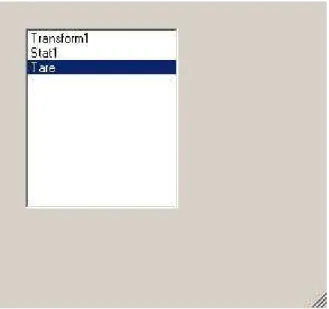
We have cobbled together an editor, however, at present, it is quite cumbersome to use and we have been experiencing some difficulty with implementing it in a more general sense. Wizard type interfaces, while useful to a novice, are often viewed as restrictive and clumsy once a user becomes familiar with the task to be performed. This may indicate our approach isn’t optimal and that we should try something different. Some screenshots of the editor application are shown below – they are presented more to illustrate the tasks that any editor will be required to perform rather than as a method of achieving these tasks.
Figure 1: Command Procedure Editor
Figure 9: Command Procedure Editor Figure 10: Editing Transform1
Figure 13: Add a Tare Command
Figure 12: Insert a new command above the current cursor location. Note that BY has been changed to 100 in the Transform1 command
Figure 18: A For Each loop construct has been Figure 19: Move the For Each loop inserted into the command procedure terminator until the For Each
loop encloses the proper group of commands
Figure 21: Select RUN 00 as the looping context variable
Figure 23: Designate Transform1 input, AY, as a variable
Figure 22: Designate some of Transform1’s inputs as variable
Figure 24: Generate a dataset to supply the Figure 25: Key in values for dataset command procedure’s variable variable inputs. Note that
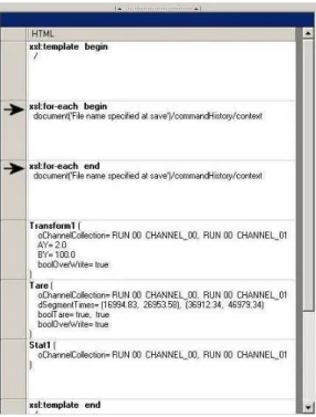
Figure 26: Command Procedure and its corresponding Dataset as presented to the user. The underlying XSL and XML for the Command Procedure and Dataset, respectively, are given in the following section.
Note that the user receives visual cues on relationships between rows in the Command Procedure and their corresponding column inputs in the Dataset. If the user clicks on a column in the Dataset then its corresponding row in the Command Procedure is highlighted and if the user clicks on a row in the
XML Dataset <commandHistory>
<context Context="RUN 00">
<command Command="Transform1" GUID="20B411EE-2F7D-4522-A226-435FCA328DAA"> <parameter Parameter="AY" Value="2" />
</command> </context>
<context Context="RUN 01">
<command Command="Transform1" GUID="20B411EE-2F7D-4522-A226-435FCA328DAA"> <parameter Parameter="AY" Value="4" />
</command> </context> </commandHistory>
XSL Command Procedure
<xsl:stylesheet version="1.0" xmlns:xsl="http://www.w3.org/1999/XSL/Transform">
<xsl:import href="file://S:/IMD Software/Migration .Net/Software-Current/IMD DispatcherClient/CommandTemplates.xsl" /> <xsl:template match="/" xmlns:xsl="http://www.w3.org/1999/XSL/Transform">
<xsl:for-each select="document('SessionHistory01.xml')/commandHistory/context" xmlns:xsl="http://www.w3.org/1999/XSL/Transform">
<command Command="Transform1" xmlns:xsl="http://www.w3.org/1999/XSL/Transform"> <xsl:variable name="GUID" select="'20B411EE-2F7D-4522-A226-435FCA328DAA'" /> <xsl:call-template name="Transform1">
<xsl:with-param name="oChannelCollection"> <parameter Parameter="oChannelCollection">
<item WorkspaceLocatorID="7F685C27-331E-4F02-88C3-1D28368C9D47" Context="{@Context}"
UserDefinedName="CHANNEL_00" PopulateMethod="Populate" DisplayFlag="false" TareFlag="false" /> <item WorkspaceLocatorID="7F685C27-331E-4F02-88C3-1D28368C9D47" Context="{@Context}"
UserDefinedName="CHANNEL_01" PopulateMethod="Populate" DisplayFlag="false" TareFlag="false" /> </parameter> </xsl:with-param> <xsl:with-param name="AY"> <xsl:copy-of select="(ancestor-or-self::node()/command[@GUID=$GUID]/parameter[@Parameter='AY'])[last()]" /> </xsl:with-param> <xsl:with-param name="BY">
<parameter Parameter="BY" Value="100.0" /> </xsl:with-param>
<xsl:with-param name="boolOverWrite">
<parameter Parameter="boolOverWrite" Value="true" /> </xsl:with-param>
</xsl:call-template> </command>
<command Command="Stat1" xmlns:xsl="http://www.w3.org/1999/XSL/Transform"> <xsl:variable name="GUID" select="'C00ED009-3DE7-4063-A455-128F5C3DD27F'" /> <xsl:call-template name="Stat1">
<xsl:with-param name="oChannelCollection"> <parameter Parameter="oChannelCollection">
<item WorkspaceLocatorID="7F685C27-331E-4F02-88C3-1D28368C9D47" Context="{@Context}"
UserDefinedName="CHANNEL_00" PopulateMethod="Populate" DisplayFlag="false" TareFlag="false" /> <item WorkspaceLocatorID="7F685C27-331E-4F02-88C3-1D28368C9D47" Context="{@Context}"
UserDefinedName="CHANNEL_01" PopulateMethod="Populate" DisplayFlag="false" TareFlag="false" /> </parameter> </xsl:with-param> </xsl:call-template> </command> </xsl:for-each> </xsl:template> </xsl:stylesheet>