Building Envelope Membrane as
Flexible Formwork for Concrete Panels
by
Chelsea Lynn Sprague
Bachelor of Science in Civil and Environmental Engineering University of Maryland, 2007
Submitted to the Department of Civil and Environmental Engineering in Partial Fulfillment of the Requirements for the Degree of
MASTER OF ENGINEERING IN CIVIL AND ENVIRONMENTAL ENGINEERING at the
MASSACHUSETTS INSTITUTE OF TECHNOLOGY June 2014
@2014 Chelsea Lynn Sprague. All Rights Reserved.
MASSACHUSETTS INS7 fTE
OF TECHNOLOGY
JUN
13 2014
LE
R
R IE S
The author hereby grants to MIT permission to reproduce and to distribute publicly paper andelectronic copies of this thesis document in whole or in part in any medium now known or hereafter created. Signature of Author:
Certified by:
_______Signature redacted
Department of Civil and Envionmental engineering
/ Ma4 0 4
Signature redacted
John A hsendorf Professor of Architecture and Civil and Environm al Enginee ng *is Superv or
Signature redacted
Heidi M. Nepf Chair, Departmental Committee for Graduate Students Accepted by:
Building Envelope Membrane as Flexible Formwork for Concrete Panels By
Chelsea L. Sprague
Submitted to the Department of Civil and Environmental Engineering on May 9, 2014 in Partial Fulfillment of the
Requirements for the degree of Master of Engineering in Civil and Environmental Engineering
ABSTRACT
This thesis investigates the use of a building envelope membrane as fabric-like formwork for exterior cladding systems in buildings. The exterior wall system (i.e., fagade) has evolved to meet the demands of the built environment including protecting occupants and interior space from the environment and, at times, create the building form and provide support for the roofs, floors and ceilings. To accommodate the demanding needs of the industry, integrated exterior wall systems have emerged. This type of panel uses traditional building materials in innovative applications. However, existing products continue to encounter some similar issues associated with traditional building methods. This research aims to propose a concept for an integrated exterior wall system that uses traditional building material in a unique application. Overall, the system will function as the building envelope as well as a load transferring mechanism. The main objective is to study the feasibility and limitations of the design through two experiments. The first experiment assesses the effect of a flexible formwork on the 28-day compressive strength of concrete formed with an array of different types of membranes. The second experiment determines the possibility of implementing an air/water barrier in a physical form-finding application. The desired outcome of the work is to evaluate the practicality of the proposed design and
further understand the implications and limitations associated with the system. As a result of the experiments, the application of air/water barriers as tension-like fabrics was found to be applicable. In addition, it was concluded that permeable membrane formwork has a
greater impact on the surface properties than the bulk concrete; however, overall the permeable membrane formwork produced a higher strength concrete.
Thesis Supervisor: John A. Ochsendorf
Title: Professor of Architecture and Civil and Environmental Engineering Thesis Reader: Caitlin T. Mueller
Acknowledgements
First and foremost, I would like to express my sincerest gratitude to my advisor Caitlin T. Mueller for her continuous support and dedication. Without her patience, motivation and guidance this thesis would not have been possible. Dr. Mueller's knowledge aided me in the research and writing of this thesis. Thank you to Professor John Ochsendorf for his
insightful recommendations, feedback and encouragements. His efforts were instrumental in the final product of the research.
Thank you to Steve Rudolph for allowing me to store materials and mix concrete in MIT facilities. In addition, I greatly appreciate his willingness to help me conduct the
experiments as well as his recommendations and ideas.
I would like to thank students in my program for their support of conducting my
experiments: Jessica Friscia, William Finney, Olivier Sylvestre, Jonathan Ellowitz and Grant Iwamoto. I would like to show my sincerest appreciation to all the contractors who
supplied the air/water barrier material for the experiments. In addition, I would like to offer my sincerest thanks to the structural design lab for their encouragement and insightful comments.
I would like to extend my appreciation to Dr. Pierre Ghisbain and Dr. Jerome Connor for
their dedication and support throughout this program.
Lastly, I would like to thank my family for their unconditional support and love throughout this entire process.
Table of Contents
1 INTRODUCTION 17
CURRENT EXTERIOR WALL TYPES 17
CONCERNS WITH CURRENT EXTERIOR WALL DESIGNS 18
INTEGRATING THE STRUCTURE AND BUILDING ENVELOPE 19
INTEGRATED EXTERIOR WALLS 20
PROBLEM STATEMENT 23
THESIS OUTLINE 24
2 INTEGRATION OF ENCLOSURE AND STRUCTURE 25
PROPOSED EXTERIOR WALL PANEL 25
RESEARCH'SCOPE 32 CURRENT RESEARCH 34 3 METHODOLOGY - EXPERIMENT 1 37 EXPERIMENT SCOPE 37 MEMBRANE FORMWORK 38 CONCRETE CYLINDERS 39 CYLINDER PREPARATION 42 COMPRESSION TESTING 44 4 RESULTS - EXPERIMENT 1 45 OBSERVATIONS 45 EMPIRICAL RESULTS 82 DISCUSSION 87 5 METHODOLOGY - EXPERIMENT 2 89 EXPERIMENTAL SCOPE 89
AIR/WATER BARRIER FORMED THIN SHELL STRUCTURE 90
THICKNESS MEASUREMENTS 92 6 RESULTS - EXPERIMENT 2 95 OBSERVATIONS 95 DISCUSSION 107 7 CONCLUSIONS 109 SUMMARY OF FINDINGS 109 DESIGN RECOMMENDATIONS 110
SIGNIFICANCE OF EXPERIMENTAL WORK ll
FUTURE WORK 112
SUMMARY OF CONTRIBUTIONS 112
APPENDIX B - CYLINDER DIMENSIONS AND EMPIRICAL RESULTS 121
Table of Figures
Figure 1-1 Types of Wall Systems
Figure 1-2 Insulated Concrete Formwork
Figure 1-3 Kenzo Unno "Unno Reinforced Concrete" Figure 1-4 Integrated Building Skin
Figure 2-1 Steel stud construction with exterior sheathing installed
Figure 2-2 Schematic design of envelope membrane formed concrete panel Figure 2-3 MFC panel schematic details
Figure 2-4 MFC panel schematic details Figure 2-5 MFC panel schematic details
Figure 2-6 Representation of permeable formwork vs. control Figure 2-7 Schematic of permeable formwork
Figure 3-1 Membrane pieces to assemble a CCW705ip cylinder Figure 3-2 Slits in the cap for a CCW705ip cylinder
Figure 3-3 Slits adhered to a body of a cylinder composed of CCW705ip Figure 3-4 Slit cut in PAB1
Figure 3-5 The CCW705vp membrane was not able to completely be removed Figure 3-6 View of cylinder C1-24 being capped
Figure 3-7 Baldwin-Tate-Emery Testing Machine
Figure 4-1 Cap made of 60-mil PVC roofing membrane by Sika Sarnafil Figure 4-2 View of mold composed of 60-mil PVC roofing membrane Figure 4-3 View of cylinder CCWvp12
Figure 4-4 View of cylinder CCWvp23 Figure 4-5 View of cylinder CCWvp23 Figure 4-6 View of cylinder CCWvp33 Figure 4-7 View of cylinder SV2 Figure 4-8 View of cylinder PAB2
Figure 4-9 View of the bottom of cylinder PAB2 Figure 4-10 View of the top surface of PAB1 Figure 4-11 View of the top of cylinder PAB2 Figure 4-12 View of the bottom of cylinder PAB1
Figure 4-13 View of the top and bottom caps for cylinder PAB3 Figure 4-14 View of cylinder SV1
Figure 4-15 View of cylinder SV2 and the air/water barrier formwork Figure 4-16 View of cylinder SV3
Figure 4-17 View of top surface of cylinder SV3 Figure 4-18 View of cylinder CW3
Figure 4-19 View of cylinder CW1 Figure 4-20 View of cylinder CW2
Figure 4-21 View of the bottom surface of cylinder CW2 Figure 4-22 View of the top surface of CW1
Figure 4-23 View of cylinder HW1 and the membrane formwork Figure 4-24 View of cylinder HW2
Figure 4-25 View of the bottom of cylinder HW3 Figure 4-26 View of the top surface of HW2 Figure 4-27 View of the top surface of C1-48
18 20 21 22 25 26 28 29 30 34 34 39 39 39 42 43 43 44 45 45 46 46 46 47 47 49 49 49 49 50 50 50 50 51 51 51 51 52 52 52 52 53 53 53 53
Figure 4-28 View of cylinder C2-48 54 Figure 4-29 View of the top surface of cylinder C1-36 54
Figure 4-30 View of cylinder C2-36 54
Figure 4-31 View of cylinder C3-36 54
Figure 4-32 View of cylinder C1-24 55
Figure 4-33 View of the top surface of cylinder C2-24 55
Figure 4-34 View of cylinder CCWip14 and the air/water barrier formwork 55
Figure 4-35 View of the bottom surface of cylinder CCWip14 55
Figure 4-36 View of the membrane formwork for cylinder CCWip24 56
Figure 4-37 View of bottom cap of cylinder CCWip24 56
Figure 4-38 View of cylinder CCWip34 56
Figure 4-39 View of the top surface of cylinder CCWip24 56
Figure 4-40 View of cylinder CCWip23 57
Figure 4-41 View of the slits on the bottom cap of cylinder CCWip23 57
Figure 4-42 View of the bottom cap of cylinder CCWip33 57
Figure 4-43 View of top surface of CCWip23 57
Figure 4-44 View of the membrane formwork for cylinder CCWip33 58
Figure 4-45 View of cylinder CCWip12 and the membrane formwork 58
Figure 4-46 View of the formwork for cylinder CCWip22 58
Figure 4-47 View of the bottom surface of cylinder CCWip22 58
Figure 4-48 View of slits in the bottom cap of cylinder CCWip32 59
Figure 4-49 View of cylinder CCWip12 59
Figure 4-50 View of cylinder CCWvp14 59
Figure 4-51 View of cylinder CCWvp24 59
Figure 4-52 View of the top surface of CCWvp24 60
Figure 4-53 View of cylinder CCWvp34 60
Figure 4-54 View of cylinder CCWvp24 60
Figure 4-55 View of cylinder CCWvp23 60
Figure 4-56 View of the top surface of cylinder CCWvp33 61
Figure 4-57 View of cylinder CCWvp23 61
Figure 4-58 View of the top surface of cylinder CCWvp13 61
Figure 4-59 View of cylinder CCWvp12 61
Figure 4-60 View of the top surface of cylinder CCWvp12 62
Figure 4-61 View of cylinder CCWvp32 62
Figure 4-62 PAB1 65 Figure 4-63 PAB1 65 Figure 4-64 PAB2 65 Figure 4-65 PAB2 65 Figure 4-66 PAB3 66 Figure 4-67 PAB3 66 Figure 4-68 SV1 66 Figure 4-69 SV1 66 Figure 4-70 SV2 67 Figure 4-71 SV2 67 Figure 4-72 SV3 67 Figure 4-73 SV3 67 Figure 4-74CW1 68 Figure 4-75 CW1 68 Figure 4-76 CW2 68 Figure 4-77 CW2 68
Figure 4-78 CW3 69 Figure 4-79 CW3 69 Figure 4-80 HW1 69 Figure 4-81 HW1 69 Figure 4-82 HW2 70 Figure 4-83 HW2 70 Figure 4-84 HW3 70 Figure 4-85 HW3 70 Figure 4-86 C1-48 71 Figure 4-87 C2-48 71 Figure 4-88 C3-48 71 Figure 4-89 C1-36 71 Figure 4-90 C2-36 72 Figure 4-91 C3-36 72 Figure 4-92 C1-24 72 Figure 4-93 C2-24 72 Figure 4-94 C3-24 73 Figure 4-95 CCWip14 73 Figure 4-96 CCWip14 73 Figure 4-97 CCWip34 73 Figure 4-98 CCWip34 74 Figure 4-99 CCWip13 74 Figure 4-100 CCWip23 74 Figure 4-101 CCWip23 74 Figure 4-102 CCWip33 75 Figure 4-103 CCWip33 75 Figure 4-104 CCWip12 75 Figure 4-105 CCWip12 75 Figure 4-106 CCWip22 76 Figure 4-107 CCWip32 76 Figure 4-108 CCWip32 76 Figure 4-109 CCWvp14 76 Figure 4-110 CCWvp14 77 Figure 4-111 CCWvp24 77 Figure 4-112 CCWvp24 77 Figure 4-113 CCWvp34 77 Figure 4-114 CCWvp34 78 Figure 4-115 CCWvp13 78 Figure 4-116 CCWvp13 78 Figure 4-117 CCWvp23 78 Figure 4-118 CCWvp23 79 Figure 4-119 CCWvp33 79 Figure 4-120 CCWvp33 79 Figure 4-121 CCWvp12 79 Figure 4-122 CCWvp12 80 Figure 4-123 CCWvp22 80 Figure 4-124 CCWvp22 80 Figure 4-125 CCWvp32 80 Figure 4-126 CCWvp32 81
Figure 5-2 25 ft x 25 ft square traced on CCW705vp membrane by Carlisle 90
Figure 5-3 CCW705ip hanging from a wooden frame 90
Figure 5-4 View of the underside of the hanging CCW705ip membrane 90
Figure 5-5 CCW705ip membrane hanging from a wooden frame 91
Figure 5-6 Vie of the CCW705ip membrane hanging from a wooden frame 91
Figure 5-7 View of the CCW705vp membrane hanging from a wooden frame 92
Figure 5-8 The nine places the specimens thickness was measured 93
Figure 5-9 Inverted envelope formed concrete shells 93
Figure 6-1 View of CCW705 hanging from a wooden frame 102 Figure 6-2 Wrinkles developed in the CCW705ip membrane 102 Figure 6-3 View of the CCW705vp membrane hanging from a wooden frame 102 Figure 6-4 The CCW705vp membrane developed wrinkles and corrugations 102 Figure 6-5 View of the underside of the CCW705ip membrane 103
Figure 6-6 View of the underside of the CCW705vp membrane 103
Figure 6-7 View of the concrete poured over the CCW705ip membrane 96
Figure 6-8 View of the concrete poured over the CCW705vp membrane 96
Figure 6-9 View of the concrete shell cast on the CCW705ip membrane 96
Figure 6-10 View of the concrete shell cast on the CCW705vp membrane 96
Figure 6-11 Thickness measurement locations for the thin shell formed on the CCW705ip 97
Figure 6-12 Thickness measurement locations for the thin shell formed on the CCW705vp 97
Figure 6-13 View of concrete shell cast on the CCW705ip membrane 103
Figure 6-14 View of the center of the concrete shell cast on the CCW705ip membrane 103
Figure 6-15 View of concrete shell cast on the CCW705vp membrane 104 Figure 6-16 View of the center of the concrete shell cast on the CCW705vp membrane 104 Figure 6-17 View of the inverted concrete shell cast on the CCW705ip membrane 104 Figure 6-18 View of the inverted concrete shell cast on the CCW705ip membrane 104 Figure 6-19 View of the exposed concrete from removing the CCW705ip membrane 105
Figure 6-20 Indentation from a crease that developed in the CCW705ip membrane 105
Figure 6-21 View of inverted concrete shell cast on the CCW705vp membrane 105
Figure 6-22 View of the inverted concrete shell cast on the CCW705vp membrane 105
Figure 6-23 Indentations in the concrete from creases that developed in the CCW705vp 106
Table of Tables
Table 1-1 Advantages and disadvantages of current wall construction 19
Table 3-1 Permanence rating of air/water barriers 38
Table 3-2 Specimen designations 41
Table 4-1 Observation of cylinders after removing air/water barrier formwork 48
Table 4-2 Observation of cylinders after failure 64
Table 4-3 Cylinders with highest compressive strengths 82
Table 4-4 Cylinders with lowest compressive strengths 82
Table 4-5 Normalized values for Batch 2 84
Table 6-1 Thickness measurements recorded for concrete placed on the CCW705ip 98
Table of Graphs
Graph 4-1 Compressive strength of cylinders 83
Graph 4-2 Compressive strength of cylinders in Batch 1 versus Batch 2 84 Graph 4-3 Compressive strength of 4"x8" cylinders 85
Graph 4-4 Compressive strength of three different size cylinders 86
Graph 6-1 Thickness measurements recorded for concrete placed on the CCW705ip 98
1
Introduction
The primary intention of this research is to develop the framework for an exterior wall system that integrates structural engineering and building technology. The structure of a building provides an independent function as that of the building enclosure layers. Hence, current practice involves installing the enclosure materials subsequent to completion of the structure. However, what would happen if the sequence of installation was reversed?
By rethinking the application of these components, could material waste be reduced or
construction time shortened?
This chapter provides a general background of exterior wall construction and introduces the emerging concept of an integrated exterior wall. The advantages associated with these types of systems will be presented as well as several concerns. This chapter will familiarize the reader with the primary objective of the research before a more elaborate discussion in Chapter 2.
1.1 Current Exterior Wall Types
Over time exterior wall systems have changed to meet the demands of the evolving built environment. However, the overarching objectives have remained the same: protect occupants and interior space from the environment and, at times, create the building form and provide support for the roofs, floors and ceilings.
The exterior wall system, or building envelope, functions as an air, water, thermal and vapor barrier to protect the interior from the surrounding environment. A design of an enclosure system can range from a system of multiple layers each performing an
independent function to one material that resists all elements. In today's practice, an exterior wall's construction is classified into three categories: cavity, barrier or mass walls.
A cavity wall is also known as a screen or drained wall that relies on an unobstructed gap
1-1) (Lemieux and Totten, 2010). In a barrier wall design, the fagade is installed directly
over the building envelope (see Figure 1-1) (Lemieux and Totten, 2010). This system relies on the exterior surface and joints in the fagade to resist water penetration and moisture ingress. As the name indicates, a mass wall is constructed of a solid material (see Figure
1-1) and relies on the wall thickness and material's storage capacity to protect the building
from the surrounding environment (Lemieux and Totten, 2010).
It
-LOW. LI - RRMP. POR1 W
Figure 1-1 Types of Wall Systems: Barrier Wall (LEFT), Cavity Wall (MIDDLE), Mass Wall (RIGHT), Photos from Lemieux and Totten, 2010.
1.2 Concerns with Current Exterior Wall Designs
As indicated in Figure 1-1, each wall composition incorporates several standard components. First, an outer surface or fagade is installed as the defense mechanism to protect against the surrounding environment as well as provide an aesthetic appeal. In the mass wall, the fagade layer is considered the solid material typically consisting of masonry, whereas, the barrier/cavity wall usually incorporates a metal panel, exterior insulation and finish systems (EIFS), masonry or similar. Inboard of the fagade, in no particular order, is the thermal insulation, air/water barrier, interior finishes and structural elements. The air/water barrier can be self-adhered or loose-laid sheets or a trowel-applied liquid membrane. This type of air/water barrier is used in a cavity or barrier wall construction; the mass wall relies on the solid material.
Table 1-1 outlines the advantages and disadvantages of each system:
Wall Type I Advantages
I
DisadvantagesI
- Cost-effective
* Reduced exterior wall thickness
- One line of defense against environment
- Corrosion of structural elements
Barrier concealed
M Performance related to workmanship
m Regular maintenance required
Table 1-1 Advantages and disadvantages of current wall construction. Adapted from Lemieux & Totten, 2010 and Donaldson, 1991.
1.3
Integrating
the Structure and Building Envelope
The general objective of this thesis is to evaluate the feasibility and limitations of a system that integrates the structural and enclosure components of a building. However, it should be noted that the terms 'structure' or 'structural' referred to in this document do not signify the superstructure of a building. The superstructure denotes the primary structural system that transfers forces to the ground (i.e., columns, beams, slabs, etc.). The structure specified in this thesis refers to the fagade structure that transfers lateral forces to the
studs and sheathing, but this thesis investigates the concept of an alternative system to provide this function.
1.4 Integrated Exterior Walls
As the industry's requirements intensify, building methods and materials must evolve. Sustainability, reduced maintenance, high quality construction and lower cost are several demands that are becoming more difficult to accommodate with the common building technology. Hence, integrated exterior wall systems have emerged. The integrated system refers to a self-supported wall that integrates the building envelope with the structure. In several cases, this refers to expanding the standard function of the enclosure layers to unconventional roles allowing for a potential diminution in cost and increased speed of construction.
Different products have been introduced in practice while others are still under
development in research. The following provides a generalized list of existing integrated exterior wall systems:
Figure 1-2 Insulated Concrete Formwork, Photo from Insulating Concrete Formwork Association.
* Dual-Purpose Formwork - Insulating panels are used as formwork for concrete and
" Insulated Concrete Forms (ICF) -Two foam layers (i.e., insulation) are used as formwork and remain in-place to function as the buildings thermal insulation (see Figure 1-2).
= FastFoot - Developed in 1986 by Fab-Form Industries, FastFoot is a high-density polyethylene fabric used to form concrete footings. The formwork can remain in-place and perform as the damp proof membrane that inhibits moisture from entering the interior.
=
Kenzo Unno - After the Kobe earthquake on January 17, 1995, Japanese architect Kenzo Unno invented the cast-in-place fabric-formed concrete walls known as "Unno Reinforced Concrete (URC)" (see Figure 1-3). This entails using acombination of rigid insulation and plastic netting as formwork. The rigid insulation becomes the permanent insulation layer for the building.
Figure 1-3 Kenzo Unno "Unno Reinforced Concrete". This is a cast-in-place fabric-formed concrete wall. Photo by CAST: The Centre for Architectural Structures & Technology.
** Insulated Wall Panels -A multitude of products have been patented that integrate the
fagade with insulation panels. For example, the Sandwich Wall System by Landheer
(1990) consists of metal panels installed over an insulating core. The Foam-in-Place
that separates an outer and inner facing sheet with a foam-in-place core to prevent thermal bridging. A more common product is Structural Insulated Panels, SIPs (founded
by Structural Insulated Panel Association). SIPs include an insulated foam core
sandwiched between two facings, typically oriented strand board (OSB).
Figure 1-4 Integrated Building Skin developed by Block and Veenendaal. Photo from Block and Veenendaal (2013).
+
Integrated Building Skin - Currently under research by Block and Veenendaal, this panel includes an ultra-thin concrete shell with soft PV thermal cells, a solar thermaldistribution layer, waterproofing, AeroGel insulation and a radiant heating distribution component (see Figure 1-4). The intent of the panel is to optimize the thermal
performance while minimizing the thickness (Block and Veenendaal, 2013).
+ Vertical Form-finding Concrete Panels - The Centre for Architectural Structures and Technology (CAST) is performing research related to thin-shell concrete panels constructed using form-finding techniques. This project includes producing molds for thin-shell wall panels by vertically hanging sheets of fabric and spraying concrete against the material. The structure is able to obtain the necessary strength and stiffness from the curvature and folds that develop when hanging the material.
All of the integrated systems offer large reductions in material waste typical during
construction. For example, traditional building practices for constructing concrete walls use timber formwork. This type of material requires not only time to install but time to remove and clean after the concrete has cured. In addition to the increase in labor, a large
volume of the material cannot be reused. The dual-purpose formwork removes the need for disposable rigid molds, decreases the amount of construction waste and increases the economic benefits.
The performance of conventional walls are highly workmanship-dependent and require a great deal of coordination between multiple trades. Considering the majority of integrated exterior wall systems are pre-formed units, the systems are built under factory conditions and are typically more accurate and dependable. This provides reduced construction time and lessens the demand for traditional building skills, which is associated with a cost savings. Pre-formed units also provide single source responsibility allowing accountability to be encapsulated by one manufacturer.
1.1.1 Concerns with Existing Products
The systems presented above have the capacity to improve construction and reduce waste, ultimately improving the cost of a project. However, the products currently in practice continue to encounter some similar issues associated with traditional building methods. For example, the ICF includes casting a concrete wall between two panels of rigid
insulation. Although the insulation remains in-place to act as the insulating layer, reducing construction waste and labor, the wall continues to consume a large volume of area,
diminishing a sizeable amount of occupiable space. Additionally, considering the systems are panelized, the aesthetic design is restricted.
The existing systems do not completely integrate the building envelope with the structure and are missing critical enclosure layers. The designs require further development to provide a fully integrated system in terms of the envelope membrane and structural support. This thesis addresses this need.
1.5 Problem Statement
What if a panel was developed that used minimal material while providing improved performance from a building technology standpoint as well as allows architectural flexibility? What if an enclosure membrane could act as the tension fabric in a physical
form-finding technique to construct an integrated exterior panel? The primary objective of this thesis is to explore the feasibility and limitations of an integrated exterior wall system that uses traditional building material in a unique application. This document proposes a schematic design for a thin shell concrete structure fabricated with physical form-finding techniques using an envelope membrane as a fabric-like material.
1.6 Thesis Outline
Chapter 2 introduces the proposed integrated exterior wall system. This system includes using enclosure membranes in a unique application to ultimately combine the building technology and structural components of a building. This chapter provides an overview of the research questions as well as a critical literature review outlining previous work in this area.
Chapter 3 provides a detailed description of the first experiment that evaluates the
feasibility and limitations of the proposed system. This chapter emphasizes the procedures performed to allow the reader to understand the experimental practices. Chapter 4
presents the results and provides a discussion assessing the outcome.
Chapter 5 and 6 present the methodology and results of the second experiment as well as provide a discussion assessing the outcomes. The final chapter, Chapter 7, provides a summary of the findings and contributions as well as recommendations for future work to improve the understanding and design of the proposed integrated panel.
2 Integration of Enclosure and Structure
This chapter introduces the proposed integrated exterior wall panel and outlines a general design. Several advantages of the system are discussed as well as a broad comparison with existing systems. This study investigates the potential design limitations as well as the feasibility of the proposed panel. Specifically, this chapter presents the research scope followed by a literature review.
It should be noted that the premise of this thesis is to investigate the concept of an
integrated system and does not provide a complete design. This research primarily focuses on qualitatively and experimentally analyzing several possible limitations of the panel.
Further work is needed to fully develop the design for the integrated exterior wall panel.
2.1 Proposed Exterior Wall Panel
Air/water barriers are conventionally installed outboard of interior finishes to prevent infiltration of bulk air and water. The placement within the exterior wall assembly varies depending on the location and function of the building.
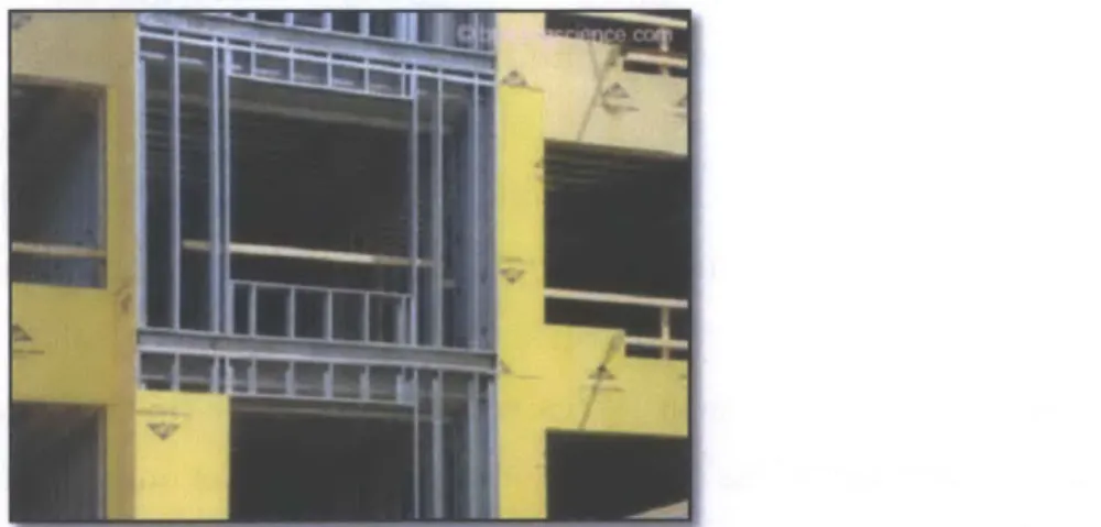
Figure 2-1 Steel stud construction with exterior sheathing installed. Photo by Lemieux, 2010.
The construction sequence for standard building practice entails first erecting the primary structural frame (i.e., beams, columns and slabs) followed by placing studs between floors
and attaching the exterior sheathing (see Figure 2-1). The enclosure material, such as the air/water barrier, can then be installed on the building. This process requires multiple levels of coordination between trades and an abundance of material waste. In addition, the performance of the wall is highly workmanship dependent.
c (ET-IANF L
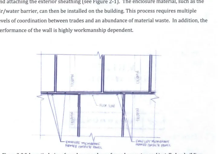
Figure 2-2 Schematic design of envelope membrane formed concrete panel installed on building.
This thesis explores the feasibility of the concept for a Membrane Formed Concrete Panel
(MFC) (see Figure 2-2). Using form-finding techniques, the panel expands the standard function of typical building materials to integrate structure with enclosure layers. The integrated exterior wall panels, introduced in Section 1.4, address the same basic concerns of building practice that the MFC aims to tackle. However, MFC includes a thin shell
concrete structure molded from an air/water barrier. The result is a system that in theory contains no bending or shear forces, reducing the amount of material consumed and ultimately producing less construction waste. This is not only a sustainable construction method but also provides an economic benefit.
2.1.1 MFC Design
The overarching objective of the MFC is to provide a system that functions as part of the building envelope as well as transfer lateral forces to the structural frame. The panel is
fabricated using vertical form-finding techniques with an air/water barrier as opposed to a tension fabric. The membrane overhangs the concrete along the bottom and two sides to allow integration between adjacent panels. In this application, the air/water barrier prevents bulk water and air from infiltrating into the interior as well as functions as the formwork for the thin shell. This will produce a lightweight structure that is able to transfer self-weight and wind loads to the primary structural components (i.e., beams,
columns and slabs). It should be noted that this panel can resist only lateral loading and is not intended to perform as a primary structural element. Schematic drawings detailing the panel components explained below can be found at the end of this section.
Panels will be installed in a staggered pattern on the face of the slabs with the membrane facing the exterior as shown in Figure 2-2. Between panels, a gap several inches wide will prevent the panels from damaging each other; the size of the gap will depend on the building design and constraints for the project. Inserts will be embedded into the concrete during fabrication. The inserts will be located, as necessary, along the top of the panel to allow a slotted connection to the face of the slab. Each panel will include a groove along the width of the bottom edge. A structural element with a hook geometry embedded into the top of the slab below will project outward above the panel underneath and be captured in the groove of the panel. This mechanism inhibits lateral but permits vertical movement.
A building's durability and performance relies on the continuity of the enclosure systems
over the face of the wall. Considering the MFC is a panelized system, integration of the air/water barrier between panels is imperative to prevent water and air from penetrating to the interior. Additional membrane along the bottom will overlap panels beneath in a shingle-style in that, the upper pieces will overlay the lower panel. This configuration prevents reverse laps and provides a drainage plane to direct incidental water down the wall. The air/water barrier along the sides will overlap adjacent panels. Compressive material (e.g, foam backer rods) will be installed between panels to form a bellow-shape for movement capabilities.
S
S
S -, S
V
Figure 2-3 MFC panel schematic details.
IN kA~ t~WQ~
I>
U4 ?4U1X
Figure 2-4 MFC panel schematic details.
I
I
I
1
I
- ~ ... - -- - , . A--
iv~--Il
11
II
N
Figure 2-5 MFC panel schematic details.
... ... ... .... .... ... ... -...
2.1.2 MFC Advantages
This design approach investigates the feasibility of combining multiple functions into one material to decrease construction waste and reduce coordination between multiple trades. Using one material to form and protect the wall will reduce cost and save time as the need for removable formwork is eliminated. In addition, the single source construction will provide sole responsibility to one manufacturer, which will reduce interface issues between multiple materials and allow one-step installation. Considering the panel is prefabricated, the risk of construction error is reduced given the panel will be produced in a controlled environment.
An ongoing maintenance program should be implemented to maintain the aesthetics and function of a fagade over the life span of a building. Without a reasonable level of
maintenance, premature deterioration of the fagade elements can occur, entailing costly repairs. Given the panelized construction and simple detailing, the MFC require minimal maintenance and are easy to remove without interfering with adjacent panels. Provided a panel needs to be replaced, the membrane can be effortlessly cut around the edges in order for the panel to be lifted out of place. Once a new MFC is installed, the additional membrane around the edges can be integrated with the existing panels. A strip of membrane will be placed between the top of the new panel and the bottom of the panel above to provide a continuous enclosure; all exposed edges of the strip will be sealed with a compatible sealant.
2.1.3 MFC vs. Existing Systems
The concepts of existing systems (see Section 1.4) such as the dual-purpose formwork or insulated wall panels are similar in scope to the envelope membrane formed concrete
panels. Both designs incorporate a notion regarding the integration of the enclosure materials with the structural elements of a building. However, the MFC highlights the importance of an air/water barrier, where as, the existing systems are focused on primarily the thermal element. Both properties are critical from a performance standpoint, but
Specifically, the insulated concrete forms rely on a protective sealant applied to the exterior face of the insulation to defending against the environment (this refers to the installation of
ICF above-grade). Although initially this may provide sufficient protection, the long-term
durability of the system will require frequent maintenance to conserve the integrity of the sealant. From a waterproofing standpoint, a dedicated membrane is more effective than sealant to resist bulk water. The MFC includes a more reliable system of waterproofing to resist bulk water penetration.
A majority of the existing systems and the MFC employ a single material to perform
multiple functions, which reduces material consumption and construction time. Given the MFC are fabricated in a controlled environment and transported on site, the probability of construction error is reduced and the quality of the panel increased. The existing systems are erected in situ and rely heavily on the workmanship of the contractors to provide an adequate panel. In addition, prefabrication will potentially lessen construction time as the panels will only need to be installed and integrated upon arriving on site; the existing systems entail installation of the components as well as construction of the system.
2.2 Research Scope
The existing products rely on the concept of integrating the structural and building envelope components. This research is similar in scope; however, the feasibility and limitations of installing an air/water barrier in a physical form-finding application is an original idea that will be assessed in this research.
The MFC employs an air/water barrier in two ways: to prevent bulk water and air from entering the interior and to perform as the formwork for a thin shell concrete structure. The latter is an anomalous function for an air/water barrier and the implications of such an application are unknown. To better understand the feasibility and limitations of the
proposed design, two experiments were conducted.
The first experiment studies the relationship between formwork permeability and the compressive strength of the concrete. The building enclosure is composed of a variety of
materials to control the migration of air, water, vapor and heat. Thermal insulation
prevents heat flow, air barriers restrict airflow, a water resistive barrier inhibits bulk water and a vapor retarder averts vapor diffusion. All components must work together to
provide a well-controlled indoor environment for occupants. Although each barrier is designed to manage a specific element, various products are able to perform multiple
functions. For example, an air/water barrier provides protection against air infiltration and water penetration but can also behave as a vapor retarder. An air/water barrier is deemed
either vapor impermeable or permeable based on the physical properties of the material composition. According to the Building Science Corporation (2006), a material's vapor permanence characteristics are classified as follows:
1. Vapor Impermeable -- 0.1 perm or less
2. Vapor Semi-impermeable
+
1.0 perm or less and greater than 0.1 perm3. Vapor Semi-permeable 4 10 perms or less and greater than 1.0 perm
4. Vapor Permeable - Greater than 10 perms
To provide a flexible design for the MFC that can be installed in multiple climates and building types, the air/water barrier could also function as a vapor retarder. Given that standard formwork is a vapor impermeable material and the panel could potentially incorporate a vapor permeable membrane, Experiment 1 assesses both the effect an air/water barrier and air/water/vapor barrier membrane formwork has on the 28-day compressive strength of concrete.
The second experiment studies the constructability issues related to using an air/water barrier as flexible formwork. Typically an air/water barrier is installed subsequent to the exterior sheathing to provide a surface for adhering the membrane. However, the MFC includes physical form-finding techniques that entail first hanging an air/water barrier followed by pouring concrete over the membrane to form a thin shell concrete structure with an integral air and moisture resistive layer. A second experiment (i.e., Experiment 2)
implementing the air/water barrier in a form-finding application will determine the feasibility of such practice.
Although installing an air/water barrier in physical form-finding techniques is a new concept, similar work has been conducted regarding the effect of permeable formwork on concrete's strength properties. The following section will present existing work that has been conducted in this field.
2.3 Current Research
Overall, there is no work that addresses the application of an air/water barrier in a form-finding application or as concrete formwork. However, limited research has been
conducted regarding the use of permeable formwork, similar to the idea of employing a vapor permeable air/water barrier as concrete formwork. The following describes the
recent work conducted to better understand the effect of permeable formwork on concrete. 1 (Refcrtenx)
2 With drainage hole and
Type I geotext + Hessian) D *nsIe
Frord vt 0 A-A cvcwi on
(With dramnage hole and Type I gcotextIe)
Top ve A
Figure 2-6 Representation of permeable Figure 2-7 Schematic of permeable formwork. formwork vs. control. Photo by Arslan 2011. Photo by Arslan 2011.
"Controlled Permeable Formwork (CPF) is a technique developed specifically for improving the near surface of vertical and inclined concrete without employing the use of additives or surface coatings" (Elliott, Jones, Schubel and Warrior, 2008). The premise behind the permeable formwork is that voids created in the layer of concrete in contact with the CPF
.
are filled with cement, aggregates and water from surrounding areas. This movement eventually produces concrete in the surface zone with a lower water-to-cement ratio compared to that of the bulk concrete (Suryavanshi & Swamy, 1997). In summary, the permeable formwork allows air and water to escape but retains the cement and other fines. CPF decreases the occurrence of blowholes and provides a more aesthetically pleasing surface. In addition, the permeability of the concrete is lessened (Price & Widdows, 1991). These reductions increase the durability of the concrete as the quality of the cover (i.e., surface zone) increases and provides better protection against an environmental attack (Arslan, 2011). Experiments have been conducted to determine the effect CPF has on the compressive strength and surface hardness of the near surface zone for concrete. A distinct increase in the compressive strength was noted and attributed to the fact that permeable formwork yields a surface zone with a greater volume of cement (Price & Widdows, 1991). The surface hardness showed improved strength compared to that of concrete cast against impermeable formwork (Price & Widdows, 1991).
The existing research conducted suggests that concrete formed with CPF has superior surface properties than concrete cured in impermeable formwork (Arslan, 2011). The experiments assessed permeable formwork including a spunbonded polypropylene fabric, "Zemdrain Membrane", type I and II geotextile (non-woven) fabric, a polypropylene
drainage medium. Although these studies incorporate permeable fabrics, none of the experiments investigate the effect a permeable air/water barrier has on properties of concrete. In addition, the experiments apply the permeable formwork in a standard, vertical wall configuration. Based on the outcomes of the existing work, this thesis will
assess the application of air/water barriers of varying permanence ratings in a physical form-finding technique. The effect the formwork has on the bulk as well as the surface of the concrete will be assessed.
The following chapters will present the methodology employed to evaluate the following:
1. The effects of air/water barrier formwork on the strength properties of concrete.
2. The effect of the permanence rating of the air/water barrier formwork on the 28-day compressive strength of concrete.
3. If an air/water barrier (vapor permeable and impermeable) can function as a
tension-like fabric.
4. The bond between the air/water barrier (vapor permeable and impermeable) and concrete.
Chapter 3 will present the methodology of Experiment 1 and Chapter 4 will discuss the results. Experiment 2's methodology will be introduced in Chapter 5 and the results will be examined in Chapter 6.
3
Methodology
-
Experiment 1
In this chapter, the methodology for Experiment 1 will be presented. The first section provides an outline of the experiment's scope. The procedures to construct the formwork and prepare the cylinders for testing will be discussed. Subsequently, the process of testing the cylinders will be explained.
3.1 Experiment Scope
As mentioned in Chapter 2, the membrane formed concrete panel (MFC) will be fabricated using physical form-finding techniques. However, alternative to the traditional tension fabric, the MFC includes hanging an air/water barrier to shape the thin-shell concrete structure. The following will be evaluated in Experiment 1:
1. Can an air/water barrier adequately perform as formwork for concrete as
conventionally air/water barriers function to only prevent the environment from penetrating into the interior?
2. Considering certain air/water barriers act as vapor barriers, does the permanence rating of the air/water barrier have an effect on the 28-day compressive strength and/or only the surface properties of concrete?
The scope of the experiment includes casting and compression testing 4" in diameter and
8" tall (i.e., 4"x8") concrete cylinders to evaluate the effect the permanence of the
membrane formwork has on the compressive strength of concrete. Twelve molds were constructed of four air/water barriers including Perm-a-Barrier by Grace Construction, Sarnavap by Sika Sarnafil, Tyvek CommercialWrap and Tyek HomeWrap by DuPont. Additionally, considering previous research concluded that permeable formwork only
impacts the surface properties of concrete (see Chapter 2), three different sized molds were casted and compression tested. Eighteen molds, three 2" (diameter) x 4" (height), 3" (diameter) x 6" (height) and 4" x 8" molds, were constructed from CCW705vp and
CCW705ip by Carlisle. It should be noted that for the reminder of this document
membranes, respectively. Plastic molds of each size were used as controls. The different sized molds were constructed to provide insight regarding whether only the surface and/or the bulk concrete properties are affected.
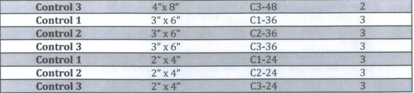
Table 3-1 outlines the permanence rating of each membrane.
_____ A/W Barrier ____ _______
Perm
Product Manufacturer Perm Imperm Rating Thickness Composition -(perms)
Perm-a-Barrier Grace X 0.05 0.041 in Aluminum faced film
Aluminum
SBS modified
bitumen membrane
Semi- with a high-density
Sarnavap Sika Imperm. 0.017 0.032 in polyethylene grid laminated between
two layers of
polyethylene film
Commerci Tyvek X 23-28 0.0079 in High-density
alWrap polyolefin
HomeWra Tyvek X 54-56 0.006 in High-density
p polyethylene
Composite membrane with CCW705ip Carlisle X 0.08-0.1 0.04 in rubberized-asphalt
adhesive laminated to poly film
Composite
CCW705v membrane with
Carlisle X 11-16 0.02 in breathable film coated with a
permeable adhesive
Control - X - - Plastic
Table 3-1 Permanence ratings of air/water barriers.
3.2 Membrane Formwork
The following outlines the methodology to construct the 4" x 8" membrane formwork. The 2" x 4" and 3" x 6" cylinders were constructed in a similar fashion.
Figure 3-1 Membrane pieces to assemble a Figure 3-2 Slits in the cap for a CCW705ip
CCW705ip cylinder. cylinder.
A. To construct the body:
a. Measure and cut an 8" x 13" rectangle (see Figure 3-1).
b. Roll the membrane into a cylinder with a 4" diameter.
c. Adhere edges or, where applicable, tape membrane edges together.
B. To construct the top and bottom:
a. Measure and cut two 5" diameter circles.
b. Draw a 4" diameter circle centered inside the 5" circle cutouts.
c. Make small cuts around the circumference of the cutouts from the edge to the 4" diameter circle (see Figure 3-2).
C. To assemble the cylinder, adhered the slits of the bottom to the cylinder (see Figure 3-3). Where applicable, tape the slits to the cylinder.
D. Subsequent to pouring the concrete, place the tops on the cylinders in a similar manner to step C.
Figure 3-3 Slits adhered to body of a cylinder composed of CCW705ip.
3.3 Concrete Cylinders
ASTM C172/C172M - 14 Standard Practice for Sampling Freshly Mix Concrete was
followed to cast twenty-one 4" x 8" cylinders with Quikrete concrete. ASTM C172/C172M is only applicable to cylinders with a volume greater than 1 cu. ft.; therefore, only the 4" x 8"
cylinder were cast using the ASTM Standard. However, the 2" x 4" and 3" x 6" cylinders were cast using a similar procedure.
Two 80-lb bags and one 60-lb bag of Quikrete were mixed according to the manufacturer's instructions. Provided the Quikrete set fairly quickly, one bag was mixed at a time. Given that the 80-lb bag yielded approximately 0.6 cu. ft., ten 4"x8" cylinders were poured with one 80-lb bag and eleven 4"x8" cylinders with the other 80-lb bag. The 60-lb bag yielded approximately 0.45 cu. ft. and allowed all eighteen 2"x4" and 3"x6" cylinders to be poured at once. Table 3-2 outlines the abbreviations designated to each cylinder as well as which cylinders were poured in each batch. It should be noted that the cylinders will be referred to by their respective abbreviation for the remainder of the document.
The following delineates the procedures for mixing and pouring the concrete, see Appendix
A for photos of this process. The release liner on the Perm-a-Barrier, Sarnavap, CCW705ip
and CCW705vp cylinders was removed prior to pouring the concrete.
A. Mixing Concrete
i. Empty concrete into mixing container.
ii. For the 80-lb bag, approximately 3.7 L of water was added until a moldable consistency was achieved. For 60-lb bag, approximately 3.1 L of water was added.
B. 4"x8" Molds
i. One layer of concrete was placed in the mold to a height of 4".
ii. The concrete was consolidated by rodding the layer 25 times to evenly distribute the aggregate.
iii. The sides of the mold were tapped 10-15 times with a rubber mallet.
iv. A second layer of concrete was poured into mold until slightly overflowing the
top edge.
v. Only the second layer of concrete was rodded 25 times to consolidate the
concrete and evenly distribute the aggregate.
vi. The sides of the mold were tapped 10-15 times with a rubber mallet.
vii. The top of mold was struck with a back and forth motion to produce a flat, level surface.
viii. The cylinder was continually sprayed for the first 30 minutes after pouring to ensure the surface remained wet. Subsequently, the cap was placed on the mold.
C. 2"x 4" and 3"x 6" Molds
i. One layer of concrete was placed in the mold until the Quikrete was slightly overflowing the edge.
distribute the aggregate.
iii. The sides of the mold were tapped 10-15 times with a rubber mallet.
iv. The top of mold was struck with a back and forth motion to produce a flat, level surface.
v. The cylinder was continually sprayed for the first 30 minutes after pouring to ensure the surface remained wet. Subsequently, the cap was placed on the mold.
All completed cylinders were left to cure with two buckets of water under two plastic tarps
that were taped to the floor.
Perm-a-Barrier 2 4"x 8" PAB2 1 Sarnavap 1 4"x 8" SV1 2 2 Sarnava 3 4"x 8" SV3 2 CommercialWrap 2 4"x 8" CW2 2 HomeWrap 1 4"x 8" HW1 2 CW0i24"x 8" CCWi 24 CCW7Oai 3 3" x 6" CW3 2 2"x 4" CCWi 22 CCW705i 2 4"x 8" CC 6v 1 1 CCW7051 3P 4x 68" CCW 134 3 CCW705i 3 3") x 6" CCW* 33 3 CCW705v1 2 "21 x 4", CCWip12 3 CCW705vp3 2" x 4" CCWvp32 3 - "- o~7 - --Control 2 4"x 8" C2-48 1
Control 3 4"lx 8" C3-48 2 Control 1 3"0 x 6"1 Cl-36 3 Control 2 3" x 6" C2-36 3 Control 3 3" x 6" C0-36 3 Control 1 '2" x 4" CI-24 3 Control 2 2"P x 4" C2-24 3 Control 3 2"J' x 4" C3-24 3
Table 3-2 Specimen designations. Note: The specimen name refers to the membrane (i.e., Perm-a-Barrier by Grace Construction) and the number out of three specimens (i.e., 1 of 3, 2 of 3 and 3 of 3).
3.4 Cylinder Preparation
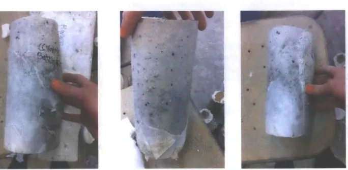
After 28-days of curing, the cylinders were uncovered and demolded. The majority of the membranes could be completely removed from the concrete. In the case of the Perm-a-Barrier membrane, a strong bond with the concrete was attained, and it could not be detached from cylinders PAB1, PAB2 and PAB3. Instead, the material was cut along the length to avoid constraining the cylinder (see Figure 3-4). CCWvp14, CCWvp24 and
CCWvp34 had similar issues; however, a portion of the membrane was able to be detached (see Figure 3-5).
Figure 3-4 Slit cut in PAB1 to avoid constraining the cylinder.
Figure 3-5 The CCW705vp membrane could not be completely removed from the concrete cylinders CCWvp14 (LEFT), CCWvp24 (MIDDLE) and CCWvp34 (RIGHT).
Subsequent to demolding, all cylinders were weighed and measured (see Appendix B). The molds were capped with Plaster of Paris by DAP to provide a level and smooth surface for
compression testing. The capping process went as follows (see Figure 3-6):
Metal Mold with 2 Prongs Cap of Plaster of Paris Rubber Band Diamond Shaped Plastic Sheet Figure 3-6 View of cylinder C1-25 being capped.
A. The capping fixture (i.e., two prongs welded to a metal plate) was cleaned by scrapping
and removing excess material and dust.
C. An acrylic sheet cut in a diamond geometry was placed on the fixture and WD-40 was
applied to the top surface of the acrylic sheet.
D. 2-parts Plaster of Paris and 1-part water was combined until a workable consistency
was achieved.
E. A generous portion of the mixture was feathered around the top of the cylinder.
F. The cylinder was placed, plaster side down, onto the acrylic sheet with the side of the cylinder placed directly against the two prongs on the capping fixture.
G. A rubber band was used to hold the cylinder against the prongs.
H. Once the Plaster of Paris hardened, steps A-G were repeated for the bottom surface.
3.5 Compression Testing
Each cylinder was compression tested in a 60 kip capacity Baldwin-Tate-Emery Testing Machine to determine the strength properties of concrete cured in an air/water barrier formwork (see Figure 3-7). The power-operated machine loaded the specimens
continuously at a rate of 1,000 psi per minute; the test was load-controlled.
The test provided the compressive strengths of each cylinder formed in an air/water
barrier. The results will be compared against each other as well as the control specimens to conclude whether the formwork affects the 28-day compressive strength.
See Chapter 4 for the experimental results and a qualitative discussion regarding the application of an impermeable versus permeable air/water barrier as formwork.
4 Results
-
Experiment
1
This chapter presents the results of the experimental work illustrated in Chapter 3.
Experiment 1 assesses the performance of six air/water barriers with varying permanence ratings. This includes monitoring the behavior of the membranes in a formwork application as well as if the permanence rating of the air/water barrier has an affect on the 28-day
compressive strength and/or surface properties of the concrete. For each of the tests, a qualitative analysis including observations from the construction process and
experimentation are described. The empirical results and a comparison of the performance of the various air/water barriers is given.
4.1 Observations
4.1.1 Construction of Membrane Formwork
Each air/water barrier was formed into a mold (see Section 3.2). During construction of the formwork, the following was observed:
Figure 4-1 Cap made of 60-mil PVC roofing Figure 4-2 View of mold composed of 60-mil PVC membrane by Sika Sarnafil. Note the rounded roofing membrane. Note sand and water leaking edges and the use of duct tape to maintain the at the gap between the cylinder and caps.
desired geometry.
1. Initially, a 60-mil PVC roofing membrane by Sika Sarnafil was intended to be used as formwork for the concrete cylinders. However, this membrane proved insufficient in
this application as the thickness of the membrane interfered with the construction of the mold. A mockup testing was performed to practice forming the molds and become aware of any unanticipated measures. The mockup included constructing three molds with the 60 mil PVC roofing membrane, CommercialWrap and Perm-a-Barrier and
casting wet sand into the cylinders. During this process, the roofing membrane would not bend to form an adequate top and bottom cap for the cylinder. The edges were rounded and did not provide a tight seal around the body of the mold (see Figure 4-1). As a result, sand leaked at the gap between the cylinder and bottom cap (see Figure
4-2). This membrane was removed from the experiment.
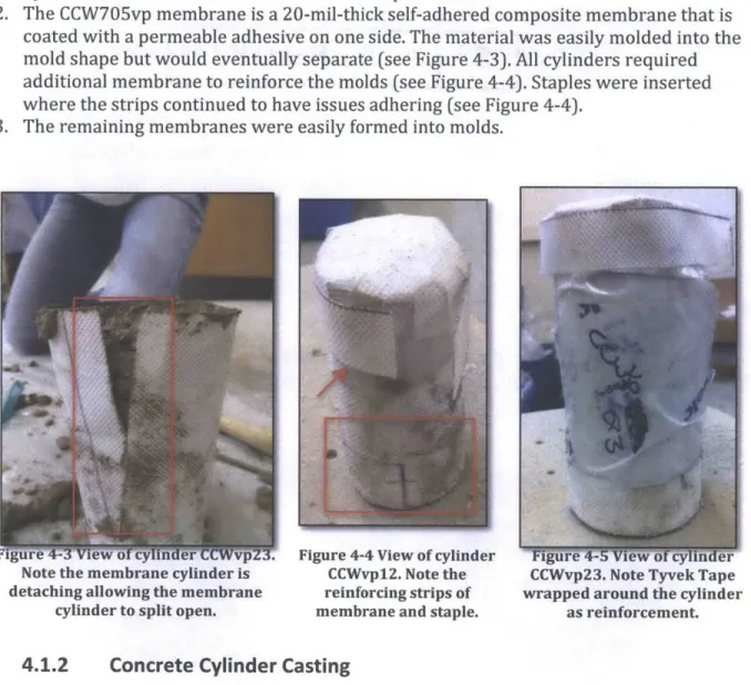
2. The CCW705vp membrane is a 20-mil-thick self-adhered composite membrane that is coated with a permeable adhesive on one side. The material was easily molded into the mold shape but would eventually separate (see Figure 4-3). All cylinders required additional membrane to reinforce the molds (see Figure 4-4). Staples were inserted where the strips continued to have issues adhering (see Figure 4-4).
3. The remaining membranes were easily formed into molds.
Note the membrane cylinder is detaching allowing the membrane
cylinder to split open.
Figure 4-4 View of cylinder CCWvp 12. Note the reinforcing strips of membrane and staple.
_ ,_7_ - - _ _ _ _ _ ,j CCWvp23. Note Tyvek Tape wrapped around the cylinder
as reinforcement.
4.1.2 Concrete Cylinder Casting
ASTM C172/C172M - 14 Standard Practice for Sampling Freshly Mix Concrete was
followed to cast twenty-one 4" x 8" cylinders with the Quikrete concrete. The 2" x 4" and 3" x 6" cylinders were cast using a similar procedure, as ASTM C172/C172M is only applicable to cylinders with a volume greater than 1 cu. ft. The following was noted during
1. As mentioned above, the CCW705vp membrane had issues with adherence. The laps in
the cylinders CCWvp14, CCWvp24, CCWvp34, CCWvp23 and CCWvp33 began detaching allowing concrete to leak (see Figure 4-3). Tyvek Tape was wrapped around the molds as reinforcement (see Figure 4-5).
2. The top and bottom pieces were constructed by making small cuts around the
circumference of the caps. The slits were adhered in a shingle-style to the outer face of the cylinder (see Figure 3-3). Upon pouring the concrete, cylinders CCWvp13,
CCWvp23, CCWvp33, CCWvp24, CCWip14, CCWip23, HW3, PAB1, PAB2, SV1, SV2, and
SV3 were noted leaking at this gap (see Figure 4-6).
3. The top of the molds became dirty as the concrete was poured and compacted. This
inhibited the top caps of cylinders SV1, SV2, SV3, CCWip14, CCWip24, CCWip23, CCWip33, CCWvp14, CCWvp24, CCWvp34 and CCWvp12 from adequately sealing the mold (see Figure 4-7).
Figure 4-6 View of cylinder CCWvp33. Note the Figure 4-7 View of cylinder SV2. Note the top cap water leaking out the bottom. is not adhered to the cylinder.
4.1.3 Cylinder Preparation
The air/water barriers were removed from the concrete cylinders after 28-days of curing. Table 4-1 displays the observations noted during removal of the formwork. It should be noted that the 'bottom' of a cylinder refers to the end placed on the floor during curing. Additionally, the bond between the membrane and concrete was ranked on a scale of 1-10.
A ten indicates the membrane formed a strong bond and could not be removed; the control
Concrete surface discolored. Fine, powdery material developed on top
surface.
Small white dots appeared around the circumference of the bottom surface. Membrane facer on the bottom cap is disintegrating, exposing the adhesive. Slits in the bottom cap detached from the
outside face of the cylinder. The adhered edges along the height that
formed the membrane cylinder were separating.
Surface of cylinder imprinted with texture of the membrane.
Surface of cylinder contained blowholes. The top and bottom of the cylinder
developed pitting. The surface of the cylinder had scouring.
The surface of the cylinder had honeycombing.
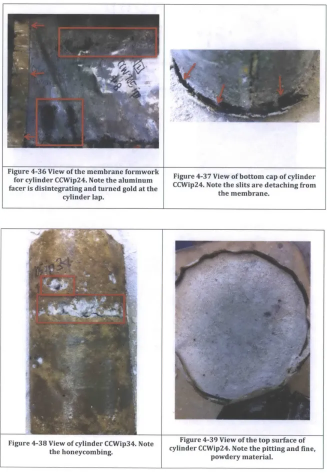
The concrete was discolored where Tyvek Tape was applied to the formwork.
Membrane facer turned gold at membrane laps. Tyvek Tape placed around the cylinder
caused the molds to become partially distorted. Pictures X I I I X X X X
I
I
X XX
X X X X X X X X X X X X X X X X X X X X X X X X XI
X X X X X X X X X X 4 -4-13 44- 4-22 4-23 -4-26 4-2- 4-34- 4-3-439 4-40 4-44 4 -4 9 -4-S 4-- 61Table 4-1 Observations of cylinders after removing air/water barrier formwork.
48
PA1 A2 S1 V WC2 HW1, C1-48, C2- C1-36, C2- C1-24, C2- CCWip14, CCWip13, CCWip12, C~p4 Cv1,C~p2 Air/Water Barrier PAnd PAB3 and, SV3 and, CW3 HW2 and 48 and C3- 36 and C3- 24 and C3- CCWip24 and CCWip23 and CCWip22 and andp2 andp2 andp2
an PB3 an V3 an C3 HW3 48 36 24 CCWip34 CCWip33 CCWip32 anad ad CCWvp34 CCWvp33 CCWvp32 Concrete-to-Membrane Bond. 10 8 1 1--77 7 5' S 3 X X X
I
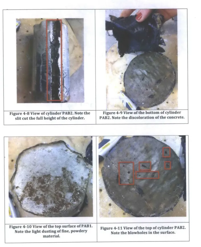
X X X X X X X X XFigure 4-8 View of cylinder PAB2. Note the slit cut the full height of the cylinder.
Figure 4-9 View of the bottom of cylinder PAB2. Note the discoloration of the concrete.
Figure 4-10 View of the top surface of PAB1. Note the light dusting of fine, powdery
material.
Figure 4-11 View of the top of cylinder PAB2. Note the blowholes in the surface.
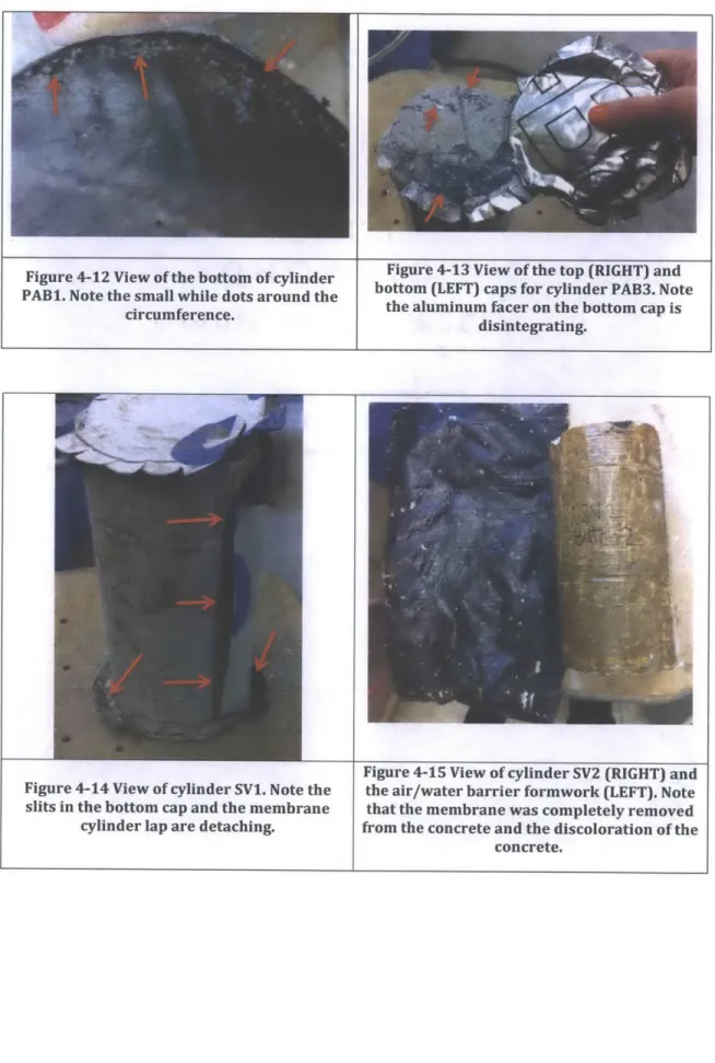
Figure 4-12 View of the bottom of cylinder PAB1. Note the small while dots around the
circumference.
Figure 4-14 View of cylinder SV1. Note the slits in the bottom cap and the membrane
cylinder lap are detaching.
Figure 4-13 View of the top (RIGHT) and bottom (LEFT) caps for cylinder PAB3. Note
the aluminum facer on the bottom cap is disintegrating.
Figure 4-15 View of cylinder SV2 (RIGHT) and the air/water barrier formwork (LEFT). Note that the membrane was completely removed from the concrete and the discoloration of the
concrete.
Figure 4-16 View of cylinder SV3. Note the surface texture and blowholes.
Figure 4-17 View of the top surface of cylinder
SV3. Note the fine, powdery material and
surface pitting.
Figure 4-18 View of cylinder CW3. Note the
discoloration of the concrete at the top and Figure 4-19 View of cylinder CW1. Note the bottom edges as well as a strip along the scouring and blowholes.