Publisher’s version / Version de l'éditeur:
Proceedings of the Eighth International Conference on Advanced Computational
Methods in Heat Transfer, 2004, 2004-03
READ THESE TERMS AND CONDITIONS CAREFULLY BEFORE USING THIS WEBSITE.
https://nrc-publications.canada.ca/eng/copyright
Vous avez des questions? Nous pouvons vous aider. Pour communiquer directement avec un auteur, consultez la première page de la revue dans laquelle son article a été publié afin de trouver ses coordonnées. Si vous n’arrivez pas à les repérer, communiquez avec nous à [email protected].
Questions? Contact the NRC Publications Archive team at
[email protected]. If you wish to email the authors directly, please see the first page of the publication for their contact information.
NRC Publications Archive
Archives des publications du CNRC
This publication could be one of several versions: author’s original, accepted manuscript or the publisher’s version. / La version de cette publication peut être l’une des suivantes : la version prépublication de l’auteur, la version acceptée du manuscrit ou la version de l’éditeur.
Access and use of this website and the material on it are subject to the Terms and Conditions set forth at
Reactive two-phase finite element flow model for materials in the
semi-solid state
Pineau, Frédéric
https://publications-cnrc.canada.ca/fra/droits
L’accès à ce site Web et l’utilisation de son contenu sont assujettis aux conditions présentées dans le site LISEZ CES CONDITIONS ATTENTIVEMENT AVANT D’UTILISER CE SITE WEB.
NRC Publications Record / Notice d'Archives des publications de CNRC:
https://nrc-publications.canada.ca/eng/view/object/?id=52880d01-4b56-4c0b-9f0f-ee18de6c982f https://publications-cnrc.canada.ca/fra/voir/objet/?id=52880d01-4b56-4c0b-9f0f-ee18de6c982fI I I I I I I IMI2003-102722-G CNRC 46819 I I I I I I I I I I I I I I I I I I I I'
Reactive
Two-Phase
Flow Model for
Materials
in the Semi-Solid
State
Frederic PineauAluminium Technology Center, National Research Council, Saguenay, Canada
Abstract
Semi-solid metal alloys have a special microstructure of globular grains sus-pended in a liquid metal matrix. This particular physical state of the matter can be exploited to produce near-net-shape parts with improved mechanical properties. However, the flow of solidifying metal is complex and associated data are difficult to obtain from experiments, which complicated the under-standing of the material for application in the casting industry. This paper describes a reactive two-phase mixture model for semi-solid slurries, which accounts for phase relative motion and phase conversion. It assumes that the processing material can be regarded as a solidifying binary alloy in a state of local equilibrium. The coupling force between the phase is derived on the assumption that the slurry is a fluid saturated isotropic media. The proposed methodology is implemented in a finite element code. The consti-tutive equation is derived from a set of experimental rheological data. The model is then used in a simple test case. The resulting flow and associated segregation patterns obtained are encouraging. However, further numerical experiments, to enhance the stability of the solution, as well as a thorough validation procedure are required before the model can be used to predict properly the real process.
Keywords: mixture formulation, semi-solid, thermal, change of phase, finite elements
1 Introduction I I I I I I
Semi-solid metal processing is being used increasingly for the production of structural parts that require a combination of good ductility, strength and lightness. An important advantage of this manufacturing process is its capability to obtain a more regular mold filling sequence that limits splashing and gas entrapment. However, the structure of the associated "reactive mixed phase material" and its corresponding flow behavior are extremely complicated and present some hard fluid dynamics problems.
Actually, metals in the semi-solid state are made up of partially solidi-fied grains embedded in a continuous liquid phase. During the filling stage, the flow of such mixture implies that the two coexisting phases move while phase conversion takes place within the melt. Instabilities and problems associated with the combined flow and solidification make the process diffi-cult to predict and control. Indeed, the lower temperature and higher solid fraction promote premature freezing of the slurry as it fills the. mold. Phase segregation occurs inside the material and changes locally the fluid prop-erties and phase composition. Moreover, particle shape, size and state of agglomeration as well as history of those "particles" throughout the process affect the flow.
Many problems encountered in the semi-solid metal industry motivate the need to better understand the particular constitutive behavior of the mate-rial. Experimental measurements for such partially molten material flows are difficult to perform because of the extreme conditions of temperature and pressure. In these circumstances, numerical models can be very useful to improve one's understanding on some aspects of the flow mechanisms.
Ideally, the problem should be tackled from the microscopic point of view but, the latter approach is by far too complex for industrial applications. Nowadays, continuum theories governing the bulk motion and evolution of an alloy in a state of mixed liquid and solid phase state provide the only viable means of analysis in an engineering context. Even so, the problem remains extremely difficult.
Most of the existing models for mixed phase region are based on mixture theory in which the governing equations are written for binary alloys. These theories have been applied similarly to a slurry, for which the two phase region consists of particles in suspension (e.g. Hills & Roberts [1], Loper & Roberts [2],[3], Loper [4] ) as well as to a mush, where the solid phase consists of loosely connected masses of crystal through which liquid can percolate (e.g. Hills & Roberts [1], Hills et al. [5], Hills & Roberts [6], [7], Jackson & Cheadle [8] ). In general, such fast moving mixtures are not in
thermodynamic equilibrium and the rate at which the solid phase melts or freezes as well as the rate at which constituents enter into one of the phases must be included (e.g. Hills & Roberts [1], Loper [4] ). But, the specification of those rates still represents one of the most difficult aspect of solidification theories.
In this work, "a practical" reactive thermal mixture model for two-phase slurries is considered. It assumes that the solid grains in the mixture are very small so that local phase equilibrium is established rapidly compared with the rate at which the mixed phase region evolves (e.g. the fast melting approximation of Loper and Roberts [5] ). In these conditions, all diffusion processes are instantaneous and the liquid and solid concentrations lie on the phase curve (e.g. Hills & Roberts [1] ).
I
I I I I I I I I I I I II
I 2 Model formulationThe semi-solid slurry is a very dense mixture of liquid and solid grains with strong coupling between the phases. The associated phase transformation process is very complex (multiple interfaces, grain coarsening/melting, crys-tallization from new nucleation sites). In the proposed formulation, the solid phase movement is represented by a transport equation for a specie with a source term for phase conversion. To calculate the interaction force between the phases, the portion of the continuum that represents the solid mass is assumed to be composed of constant diameter spherical particles that keep their shape even if they gain or loss mass. The calculated solid frac-tion must however be less than the maximum packing value Mp. For now, this model is viewed as a base model on which more sophisticated features will be included latter i.e., solid packing effects, history of the particles and thixotropy.
2.1 Mixtlll'e flow equations
The isothermal mixture flow model presented in reference (Pineau [9])is
fur-thered developed to account for non-isothermal effects. The Navier-Stokes equations are applied to both the liquid and solid phases, with the solid treated as a pseudo-fluid. The final forms of the flow equations are repro-duced here for completeness.
The mixture mass balance and momentum equations are respectively given by:
'" -0
UPm + V .
TDm = -Pm [asUmsUms
+
(1- as)UmIUmc] (3)I
I I I I I I I I I I I II
I I I I II
I I II
I
I
I
a
at (Pmum)
+
'V. (Pmumum) = -'Vpm + 'V. Tm + 'V. TDm (2) where TDm is a diffusion stress, which represents the momentum convected by the relative motion between the liquid and solid phases:with as being the solid phase volume fraction.
The diffusion velocities Ums and Uml are respectively given by (e.g. Man-ninen & Taivassalo [10)):
Ums = (1- as) (us - uz) Uml = -as (us - UI)
(4) (5) where the term (us - uz) represents the relative velocity between the phases.
2.2 Conservation equation for the solid phase
The local instantaneous volume fraction of the solid phase is obtained from the solid phase continuity equation in term of the mixture variables (e.g Pineau [9] ):
a
at (psas) + 'V. (psas (um + ums)] = Psfs (6)
where fs is the rate of solid phase production. Note that fs = -fl, the rate of liquid phase production.
2.3 Interaction between the phases
For semi-solid metal applications, the slurry is viewed as a fluid saturated isotropic porous media. The phase interaction term, (e.g. Pineau [9] ), that appears in the momentum equations of each phase, is given by:
alJ.L1
MI
= Ms = PI'Val+ J{ (us - uz)
(7)
where J{ is the permeability of the porous media obtained from the Carman-Kozeny relation:
d2
(
1 - a3)
J{
-
-
p s2
180 (as)
where dp is the particle diameter. In eqn (7), al is the liquid phase
vol-ume fraction and PI is the liquid phase pressure, (= Ps = Pm which are
respectively the solid phase and mixture pressures).
I
I
I
I
Eqn (7) is then substituted in the liquid phase momentum equation to give (e.g. Pineau [9] ):
8 ~~
8t (a/p/u/) + V0 (a/p/u/ut)
=
-a/Vp/ + V. am +K
(us
- ut) (9)For semi-solid slurries, the volume solid fraction is high, (0.4 and up), and strong pressure gradients are expected. Consequently, relative velocities between the phases are assumed to depend mainly on the pressure gradients and all the other terms in eqn (9) are neglected:
K (us - ut) = -VPm
p/
Finally, the mixture viscosity Pm is given by a Cross model (e.g. Pineau
[9] ) 0
(10)
2.4 Conservation of energy for the mixture
In the same way, the statement of energy conservation for the mixture is obtained by summing the energy equations for each phase, which gives after decomposition ofthe advective terms and some algebraic manipulations (e.g.
Bennon & Incropera [11]): 8
8t (Pmhm)+PmumV. hm- V. (kmVT) - V. [Pmasums(h/ - hs)] = 0 (11)
where the mixture enthalpy hm is given by:
Pmhm = psashs + (1- as) p/h/ hs = CpT + ho hi = CpT + ho + L ( 12) ( 13) (14) Land ho are respectively the latent heat of fusion and a reference enthalpy.
Substituting eqn (12-14) in eqn (11) and rearranging, the mixture energy equation in term of the temperature is obtained:
[ 8T ] [ 8as ] PmCp {jt+umoVT -PmL 7ft+UmoVas - V . (km VT) - V . [PmasumsL] = 0 ( 15) In eqn (15), phase change effects are accounted for by the second term in brackets while the last term represents the energy transport due to the relative motion between the phases.
I
I
I
I
I
2.5 Rate of phase change and phase composition
To close the system of conservation equations, the rate of phase change in eqn (6) as well as the composition of each phase must be specified.
In order to derive the rate of phase change term, the slurry is regarded
as a binary alloy. The rates of production of one constituent, (say 13),in the
solid and liquid phases are respectively given by (e.g. Hills & Roberts [1] ): fJ S s PtJ
+
" s s mtJ =7ft
v. PtJvtJ 1 fJp~ 1 1 mtJ= 7ft + \1
. PtJvtJ (16) (17)where P~ is the partial density of constituent 13 in phase k:
k
-
kPtJ
= Pm
,pk~ ,k=
l,S (18)with
~
k being the mass fraction of constituent 13 in phase k and, ,pk, themass fraction of phase k:
,pk
=
QkPkI:k QkPk
The specification of these rates, (eqns 16 and 17), is very challenging but, by using the fast-melting approximation of Loper & Roberts [2], this difficulty is avoided (e.g. Hills & Roberts [1] ).
Mass conservation of constituent 13 in the liquid-solid system yields:
(19)
s I
0 mtJ+mtJ
=
Eqns (16) and (17) are substituted in eqn (20) to give:
(20)
-m
D~ = - \1 . i
Pml5t (21)
where
~
m denotes the mass fraction of constituent 13of the mixture:-m -8 -I
~
= ,pS~ + (1- ,ps)~ (22)Inserting eqn (22) in eqn (21) gives (e.g. Hills & Roberts [1] ):
- s -I
(
- s - I)
D,ps
D~
D~.
Pm ~ - ~ Dt + Pm,pS
Dt
+ Pm (1 - ,ps ) Dt = \1 .Iwhere i is a diffusion flux given by:
(
)
( )(
)
1= Pm'!'..., VI3- V + Pm 1 - rp.
~
vl3 - V+ Pmrp.(1- rp.) (~. - ~ I) (vi - v') (24)
For semi-solid metal processing, the first term is dropped since diffusion in the solid is considered negligible during the time of injection. The mixing in the liquid phase is supposed to be strong enough to have v~ close to vi. Consequently, the second term is also dropped.Substituting eqn (4) in the third term of eqn (24) yields:
.
(
-.
-I
)
1= - Pmrps
~
-~
Urns (25)Now, the mass concentrations
~
I and~
s must be specified. Since the solid particles embedded in the liquid metal are very small, the time-scales of melting or freezing processes are supposed to be short compared with those associated with the motion of the slurry. Consequently, phase compositions are fixed by the requirement of local thermodynamic equilibrium:~. =C(p,T), ~I =e(p,T) (26)
Next, the curvature of the solidus and liquidus are approximated as straight lines and the equilibrium partition ratio ko is used to relate the phase com-positions (e.g. Bennon & Incropera [11] ):
~
s(T) = ko~i(T) (27)Finally, the mass fraction field <Psin eqn (23)remains as the only unknown concentration to be solved. Substituting eqns (19), (25),(27) in eqn (23)
and assuming that P. = PI = Pm, the following conservation equation is obtained for the volume fraction of solid as:
oas
7ft + (um+ urns)
. 'Vas=
fs (28) withf. = 1
- a. (1 - ko) [at
+
Urn' 'Vt ] ~I (1- ko) atwhich has exactly the form of eqn (6).
I
I
I
I
II
I
I
I I I I I I I ITable 1: Calculation parameters
Physically, the rate of solid phase change is governed by the rate at which the phases experience changing thermodynamic conditions either because conditions throughout the mixture are changing temporally or because phases are migrating through conditions that vary spatially. In eqn (29),this is reflected by the change of constituent composition ~l in the system which is dictated by a local equilibrium assumption. This approach is very similar to the one used by Jackson & Cheadle [8].
Note that when there is no flow, eqn (28) reduces to the standard equi-librium relation between the solid fraction and the phase composition.
2.6 Front tracking approach
A level set technique is employed to capture the position of the flow front (e.g Ilinca & Hetu [12] ). The pseudo-concentration function is convected using the mixture velocity provided by the solution of the Navier-Stokes equations.
3 Calculations
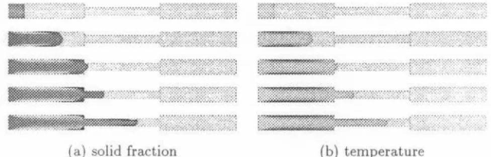
The proposed formulation has been implemented in the finite element code for mold filling applications developed at the Industrial Material Institute (e.g. Ilinca & Hetu [12]). Calculations are performed on an Origin 2000 using six processors MIPS R10000 at 195 MHz, working in parallel. The cylindrical cavity, which consist of 25990 nodes and 135609 tetrahedron elements, is depicted in Figure (1) with associated velocity boundary conditions. The slurry enters the cavity from the left at a temperature of 864 K, (which corresponds to an equilibrium solid fraction of 0.4). Heat is lost through the walls by convection (h=1000 W/s and Too=400 K) as the metal fills the mold. The materials properties employed are shown in Table (1). Some sequences of the mold filling are presented in Figure (2). The volume solid
p=
2680 kgJm3 L=
389000 J Jkg ko= 0.286f.1l=0.01 Pa.s dp = 0.001 m Mp = 0.65
7} = 888.15 K Ts= 828.15 K Tm = 936 K Cp = 1100 J J(kg.K) ks = 197.5 WJm.K kl = 89.6 W/m.K
~
0,1 m~
0.1 m 0.1 mI
I
I
I
I
I
I
I
I
I
II
I I I I I I I-..
u=O,Sm/s
~
no slipt
<p=0.02 m no slip <p=0.01 mFigure 1: Computational domain
fraction as distributions are presented on the left where the grey spectrum goes from as= 0.3 (black) to 0.55 (white). The corresponding temperature distributions are given on the right where the coldest regions are represented by the darker colors. It is shown that the liquid is repelled in the direction of the free surface (at the front). Near the wall, the solid fraction increases because of the decrease in temperature due to heat loss. The solid" created" is then convected downstream and contribute to increase the solid fraction in the boundary layer near the wall. Due to the very high non-linearities,
lIIm:i::::;?;};%;:;:m,:},:::",:,:"""":,.,,.,.:,.r'.:..:.:::::..tf:m:nfI:I~:;:::jm:[:m IlIiL'iB:;:::;::r'[:;.,...:,..:, ,,{,:,,::::,:,:,:,,:.::::,::,,:@:::r;:)[::::n:::;:g;:::iIj iWj):mC::,::::t:::~ ":"::,::,::,:,,,:,,,:,,:':::','..:{::mm:::mmlJ\lI::r::m ~nm:::K:.::r. :::.::,..:::::::::r,::::::::.:.:trI{gI[:I:Im::{::~ If.",.,,:.:tt:':':':':n{ll -!.',,:}:::,tt:;:::::::::I;::::::::;:::::::':;r::j DTIfWf@::::i¥r.:,,:..:,:,::';e::,:::,::.,:::,::.,.,:::,.,:,:,fj:::::::iIT:::.;;@{;::'g: ;:::::::::::::::::.:...:.:::.;:ji::4f~:::':::::':;':':',,::,:{::,"":::'::C:::j:I?:;:::::;::::r:'2::; ~t:::..:...:::;:::::.,..",::;:,,??t:::::~:,.::{:~n::':::.:::.:::::".::::::::tI:[{;:::::::r::.::::;"::: ~::m:.;.r:I::W:mml>::>::»»::::::::::x:,~~::::;:,.::t::::::{::/;..:::;::
(a) solid fraction (b) temperature
Figure 2: Solid volume fraction and temperature on the middle plane
convergence of the solution appears difficult. Some studies are required to understand these physical or numerical instabilities.
4 Conclusions
A mixture formulation for the flow of solid-liquid mixtures using a multi-phase constitutive model and temperature effects has been presented, The model has been implemented in a finite element code, Preliminary results are encouraging and show that the model reproduces at least qualitatively some aspects of the complex flow, However, further numerical experiments
and complete material characterization are required for truly predictive sim-ulation capabilities. I I I I I I References
[1] Hills, R. & Roberts, P., On the formulation of diffusive mixture theories for two-phase regions. J of engineering maths, 22, pp. 93-106, 1988. [2] Loper, D. & Roberts, P., On the motion of an iron-alloy core containing
a slurry, 1. general theory. Geophys Astrophys Fluid Dynamics, 9, pp. 289-321, 1978.
[3] Loper, D. & Roberts, P., A boussinesq model of a slurry. NATO
advanced research workshop on structure and dynamics of partially solidified, ed. M. Nijhoff, pp. 293-323, 1987.
[4] Loper, D., A non-equilibrium theory of a slurry. Continuum Mech
Ther-modyn, 4, pp. 213-245, 1992.
[5] Hills, R., Loper, D. & Roberts, P., A thermodynamically consistent model of a mushy zone. Q J Mech appl Math, 36(4), pp. 505-539, 1983. [6] Hills, R. & Roberts, P., A generalized scheil-pfann equation for a dynamical theory of a mushy zone. Int J Non-Linear Mechanics, 23(4), pp. 327-339, 1988.
[7] Hills, R. & Roberts, P., Relaxation effects in a mixed phase region. 1. general theory. J of Non-Equilibrium Thermodyn, 12(2), pp. 169-181, 1987.
[8] Jackson, M. & Cheadle, M., A continuum model for the transport of heat, mass and momentum in a deformable, multicomponent mush, undergoing solid-liquid phase change. Int J Heat Mass Transfer, 41(8-9), pp. 1035-1048, 1997.
[9] Pineau, F., Two-phase predictive finite-element flow model for semi-solid slurries. Proc. of the 1st Computational Modeling of Materials,
Minerals and Metals Processing, eds. J.E. M. Cross & C. Bailey, TMS:
San Diego, Ca, pp. 411-420, 2001.
[10] Manninen, M. & Taivassalo, V., On the mixture model for multiphase
flow. VTT Energy: VTT, Finland, pp. 1-62, 1996.
[11] Bennon, W. & Incropera, F., A continuum model for momentum, heat and species transport in binary solid-liquid phase change systems-I. model formulation. Int J Heat Mass Transfer, 30(10), pp. 2161-2170, 1988.
[12]Ilinca, F. & Hetu, J., Finite element solution of three-dimensional tur-bulent floes applied to mold-filling problems. Int J Numer Meth in