Publisher’s version / Version de l'éditeur:
Optical Pattern Recognition: A Critical Review, pp. 1026205-1-1026205-11,
1992-04-01
READ THESE TERMS AND CONDITIONS CAREFULLY BEFORE USING THIS WEBSITE.
https://nrc-publications.canada.ca/eng/copyright
Vous avez des questions? Nous pouvons vous aider. Pour communiquer directement avec un auteur, consultez la
première page de la revue dans laquelle son article a été publié afin de trouver ses coordonnées. Si vous n’arrivez pas à les repérer, communiquez avec nous à [email protected].
Questions? Contact the NRC Publications Archive team at
[email protected]. If you wish to email the authors directly, please see the first page of the publication for their contact information.
NRC Publications Archive
Archives des publications du CNRC
This publication could be one of several versions: author’s original, accepted manuscript or the publisher’s version. / La version de cette publication peut être l’une des suivantes : la version prépublication de l’auteur, la version acceptée du manuscrit ou la version de l’éditeur.
For the publisher’s version, please access the DOI link below./ Pour consulter la version de l’éditeur, utilisez le lien DOI ci-dessous.
https://doi.org/10.1117/12.59849
Access and use of this website and the material on it are subject to the Terms and Conditions set forth at
Recent results in rotation-invariant pattern recognition
Arsenault, H. H.; Asselin, Daniel; Chang, Shoude; Leclerc, Luc; Sheng,
Yunlong
https://publications-cnrc.canada.ca/fra/droits
L’accès à ce site Web et l’utilisation de son contenu sont assujettis aux conditions présentées dans le site LISEZ CES CONDITIONS ATTENTIVEMENT AVANT D’UTILISER CE SITE WEB.
NRC Publications Record / Notice d'Archives des publications de CNRC:
https://nrc-publications.canada.ca/eng/view/object/?id=32270f6d-9f64-42d1-aa1f-c77d415c3584
https://publications-cnrc.canada.ca/fra/voir/objet/?id=32270f6d-9f64-42d1-aa1f-c77d415c3584
PROCEEDINGS OF SPIE
SPIEDigitalLibrary.org/conference-proceedings-of-spie
Recent results in rotation-invariant
pattern recognition
H. H. Arsenault
Daniel Asselin
Shoude Chang
Luc Leclerc
Yunlong Sheng
Recent Results in Rotation Invariant Pattern Recognition
H. H. Arsenault, D. Asselin, S. Chang, L. Leclerc and Y. Sheng
Introduction
This paper reviews recent progress in rotation invariant pattern recognition; the
emphasis is on the work done in our own laboratories, since much of the significant
work done elsewhere is described in other papers presented at this conference.
Previous work was described in a previous critical review of technology,1 and we shall
only briefly review this previous material.
In previous years there has been considerable effort expended to develop digital and
optical pattern recognition techniques that are invariant to various changes of the
objects. The main kinds of invariance are invariance to translations, rotations, contrast,
scale, and deformations. Invariance is always obtained at the price of something else: for
example, rotation invariance is often accomplished at the cost of discrimination ability
or of a decrease in signal -to -noise ratio.
The two main approaches to invariant pattern recognition are matched filtering and
invariant moments. The latter, like most other pattern recognition techniques, requires
segmentation of the target from the scene, and is difficult to implement optically,
whereas the former usually affords invariance to translation as a bonus, because of the
linearity of the matched filtering system, and is easy to implement optically by means
of optical correlators using holograms as matched filters. In this paper we consider only
methods based on matched filtering.
Of particular practical interest is pattern recognition invariant under rotation of the
target. There are two kinds of rotations: in -plane and out -of -plane rotation. The easiest
kind to implement is in -plane rotation. Although considerable effort has been expended
in developing the more difficult out -of -plane rotation invariant methods, no really
convincing results have yet been published. We shall consider only in -plane rotation
problems.
The main current ideas relevant to in -plane rotation invariant methods involves the use
of Circular harmonic filters (CHF) and of composite or synthetic discriminant filters
(SDF). Before describing the use of those filters for invariant pattern recognition, we
briefly review CHF and composite filters.
Circular harmonic filters
Circular harmonic filters are based on the Circular harmonic decomposition. Any object
f(r,O) in polar coordinates may be decomposed into a series of circular harmonic
components:
65
Recent Results in Rotation Invariant Pattern Recognition
H . H . A rs e n a u lt, D . A s se lin , S . C h a n g , L . L e c le rc a n d Y . S h e n g
Introduction
T h is p a p e r re v ie w s re c e n t p ro g re ss in ro ta tio n in v a ria n t p a tte rn re c o g n itio n ; th e e m p h a s is is o n th e w o rk d o n e in o u r o w n la b o ra to rie s, s in c e m u c h o f th e s ig n ific a n t w o rk d o n e e lse w h e re is d e s c rib e d in o th e r p a p e rs p re se n te d a t th is c o n fe re n c e .
P re v io u s w o rk w a s d e s c rib e d in a p re v io u s c ritic a l re v ie w o f te c h n o lo g y ,1 a n d w e s h a ll o n ly b rie fly re v ie w th is p re v io u s m a te ria l.
In p re v io u s y e a rs th e re h a s b e e n c o n s id e ra b le e ffo rt e x p e n d e d to d e v e lo p d ig ita l a n d o p tic a l p a tte rn re c o g n itio n te c h n iq u e s th a t a re in v a ria n t to v a rio u s c h a n g e s o f th e o b je c ts. T h e m a in k in d s o f in v a ria n c e a re in v a ria n c e to tra n s la tio n s , ro ta tio n s , c o n tra st, s c a le , a n d d e fo rm a tio n s . In v a ria n c e is a lw a y s o b ta in e d a t th e p ric e o f s o m e th in g e ls e : fo r e x a m p le , ro ta tio n in v a ria n c e is o fte n a c c o m p lis h e d a t th e c o s t o f d is c rim in a tio n a b ility o r o f a d e c re a s e in s ig n a l-to -n o ise ra tio .
T h e tw o m a in a p p ro a c h e s to in v a ria n t p a tte rn re c o g n itio n a re m a tc h e d filte rin g a n d in v a ria n t m o m e n ts . T h e la tte r, lik e m o s t o th e r p a tte rn re c o g n itio n te c h n iq u e s , re q u ire s s e g m e n ta tio n o f th e ta rg e t fro m th e s c e n e , a n d is d iffic u lt to im p le m e n t o p tic a lly , w h e re a s th e fo rm e r u s u a lly a ffo rd s in v a ria n c e to tra n s la tio n a s a b o n u s , b e c a u s e o f th e lin e a rity o f th e m a tc h e d filte rin g s y s te m , a n d is e a s y to im p le m e n t o p tic a lly b y m e a n s o f o p tic a l c o rre la to rs u s in g h o lo g ra m s a s m a tc h e d filte rs. In th is p a p e r w e c o n s id e r o n ly m e th o d s b a s e d o n m a tc h e d filte rin g .
O f p a rtic u la r p ra c tic a l in te re s t is p a tte rn re c o g n itio n in v a ria n t u n d e r ro ta tio n o f th e ta rg e t. T h e re a re tw o k in d s o f ro ta tio n s : in -p la n e a n d o u t-o f-p la n e ro ta tio n . T h e e a sie st k in d to im p le m e n t is in -p la n e ro ta tio n . A lth o u g h c o n s id e ra b le e ffo rt h a s b e e n e x p e n d e d in d e v e lo p in g th e m o re d iffic u lt o u t-o f-p la n e ro ta tio n in v a ria n t m e th o d s , n o re a lly c o n v in c in g re su lts h a v e y e t b e e n p u b lis h e d . W e s h a ll c o n s id e r o n ly in -p la n e ro ta tio n p ro b le m s.
T h e m a in c u rre n t id e a s re le v a n t to in -p la n e ro ta tio n in v a ria n t m e th o d s in v o lv e s th e u s e o f C irc u la r h a rm o n ic filte rs (C H F ) a n d o f c o m p o s ite o r s y n th e tic d is c rim in a n t filte rs (S D F ). B e fo re d e s c rib in g th e u s e o f th o s e filte rs fo r in v a ria n t p a tte rn re c o g n itio n , w e b rie fly re v ie w C H F a n d c o m p o s ite filte rs .
Circular harmonic filters
C irc u la r h a rm o n ic filte rs a re b a s e d o n th e C irc u la r h a rm o n ic d e c o m p o s itio n . A n y o b je c t f ( r,0 ) in p o la r c o o rd in a te s m a y b e d e c o m p o s e d in to a s e rie s o f c irc u la r h a rm o n ic c o m p o n e n ts:
6 5
Optical Pattern Recognition: A Critical Review, edited by Joseph L. Horner, Bahram Javidi, Proc. of SPIE Vol. 10262 (Vol. CR40), 1026205 · © (1992) 2017 SPIE · CCC code: 0277-786X/17/$18 · doi: 10.1117/12.59849
where
When one component
f(r,0) =
fm(r) exp(im0)
(1)
m=mfm(r) =
f(r,0)exp(-im0) d0
0(2)
hm(r,0) = fm(r) exp(im0)
(3)
is used as a matched filter, a correlation peak whose intensity is invariant to rotations
of the object is obtained . If for an unrotated object f(r, 9), the output correlation with an
object g(r,O) is R fg(r, (3). Then for a rotated input f(r, 9 +a), the output correlation will
be
Rfg(r, 0+a) exp (ima).
(4)
This is the foundation of rotation invariant pattern recognition based on Circular
harmonic filters. Unfortunately, the unmodified CHC filter does not yield good
recognition ability, throws away most of the energy of the target, and is usually
associated with high sidelobes, so the method has had to be refined to improve
recognition performance.This has been done by combining the CHC idea with other
ideas, such as composite filters and phase -only filters.
We briefly review the main CHC filter ideas that have been published.
1) Simple CHC filter methods involve a single CHC filters or single filters made
of combinations of CHC's from different objects. The latter could might be considered
as a multiple CHC method. One proposed method involves rotating the filters
continuously while the measurements are made (lock and tumbler filter).
2)Multiple CHC methods involve combining the results from more than one CHC
filter. The correlation values from different filters are used to create a feature space from
the multiple correlation values, then the unknown target is classified using one of the
multiple criteria available, such as minimum distance in the feature space.
3) Composite CHC filters use a single filter made up of a linear combination of
filters from different objects that make up the data base of interest. The coefficients may
be chosen to discriminate in favor of or against any of the objects that belong to the data
base.
3) Moment methods do not use filters and require much more calculations than the
above methods, in addition to requiring segmentation of the targets. However moment
methods allow classification of targets not only under changes of position and of
orientation, but also under changes of scale. These methods may be more amenable to
cases where background is not a problem, as in some tracking problems. Such methods
f(r,9 ) = X fm (r) e x p (im 0 )
(
1)
w h e re
f(r,0 )e x p (-im 0 ) d 0
(
2
)
W h e n o n e c o m p o n e n t
h ra(r,0 ) = fm (r) e x p (im O )
(
3
)
is u s e d a s a m a tc h e d filte r, a c o rre la tio n p e a k w h o s e in te n sity is in v a ria n t to ro ta tio n s o f th e o b je c t is o b ta in e d . I f fo r a n u n ro ta te d o b je c tf(r,0),
th e o u tp u t c o rre la tio n w ith a n o b je c tg(r,6)
isRfg(r,6).
T h e n fo r a ro ta te d in p u t/( r,8+a),
th e o u tp u t c o rre la tio n w ill b eT h is is th e fo u n d a tio n o f ro ta tio n in v a ria n t p a tte rn re c o g n itio n b a s e d o n C irc u la r h a rm o n ic filte rs . U n fo rtu n a te ly , th e u n m o d ifie d C H C f ilte r d o e s n o t y ie ld g o o d re c o g n itio n a b ility , th ro w s a w a y m o st o f th e e n e rg y o f th e ta rg e t, a n d is u s u a lly a ss o c ia te d w ith h ig h s id e lo b e s, s o th e m e th o d h a s h a d to b e re fin e d to im p ro v e re c o g n itio n p e rfo rm a n c e .T h is h a s b e e n d o n e b y c o m b in in g th e C H C id e a w ith o th e r id e a s, s u c h a s c o m p o site filte rs a n d p h a s e -o n ly filte rs.
W e b rie fly re v ie w th e m a in C H C filte r id e a s th a t h a v e b e e n p u b lish e d .
1 )
Simple CHC filter methods
in v o lv e a s in g le C H C filte rs o r s in g le filte rs m a d e o f c o m b in a tio n s o f C H C 's fro m d iffe re n t o b je c ts . T h e la tte r c o u ld m ig h t b e c o n s id e re d a s a m u ltip le C H C m e th o d . O n e p ro p o s e d m e th o d in v o lv e s ro ta tin g th e filte rs c o n tin u o u s ly w h ile th e m e a s u re m e n ts a re m a d e (lo c k a n d tu m b le r filte r).2) Multiple CHC methods
in v o lv e c o m b in in g th e re s u lts fro m m o re th a n o n e C H C filte r. T h e c o rre la tio n v a lu e s fro m d iffe re n t filte rs a re u s e d to c re a te a fe a tu re s p a c e fro m th e m u ltip le c o rre la tio n v a lu e s , th e n th e u n k n o w n ta rg e t is c la s s ifie d u s in g o n e o f th e m u ltip le c rite ria a v a ila b le , s u c h a s m in im u m d ista n c e in th e fe a tu re s p a c e .3 )
Composite CHC filters
u s e a s in g le filte r m a d e u p o f a lin e a r c o m b in a tio n o f filte rs fro m d iffe re n t o b je c ts th a t m a k e u p th e d a ta b a s e o f in te re s t. T h e c o e ffic ie n ts m a y b e c h o se n to d is c rim in a te in fa v o r o f o r a g a in s t a n y o f th e o b je c ts th a t b e lo n g to th e d a ta b a s e .3 )
Moment methods
d o n o t u s e filte rs a n d re q u ire m u c h m o re c a lc u la tio n s th a n th e a b o v e m e th o d s , in a d d itio n to re q u irin g s e g m e n ta tio n o f th e ta rg e ts. H o w e v e r m o m e n t m e th o d s a llo w c la s sific a tio n o f ta rg e ts n o t o n ly u n d e r c h a n g e s o f p o s itio n a n d o f o rie n ta tio n , b u t a lso u n d e r c h a n g e s o f s c a le . T h e s e m e th o d s m a y b e m o re a m e n a b le to c a s e s w h e re b a c k g ro u n d is n o t a p ro b le m , a s in s o m e tra c k in g p ro b le m s . S u c h m e th o d sOptical Pattern Recognition / 67
may not so far be implemented as matched filters, but we mention them for the sake of
completeness. Moment methods are described in another paper.
4) Other methods include all methods that do not fall in the preceding
three groups.
They include methods such as coordinate transformation methods.
phase -only filters
Phase -only filters have been shown to yield sharp correlation peaks and low sidelobes,
in addition to improving filter discrimination. Since Circular harmonic filters tend to
have large sidelobes, fabricating the filters as phase -only CHC filters can be expected to
improve performance.
The phase -only CHC filter is
hm(p) = exp [jam(p) +m(I)]
(5)
where am(p) + m4 is the phase of the Fourier transform of the CHC component of
order m. However this filter is not rotation invariant, because the center correlation of
the filter with the object from which the filter, which is equal to
x
Cm
=
J. IFm(P)IPdP eXp(jm4i0)(6)
o
where 40 is the rotation angle of the target, becomes for a real filter
x
Cm = 2n
J.
1Fm(r)Irdr cos mf0
(7)
0which changes with rotation angle 00. This may be alleviated by using two
filters, a
cosine filter and a sine filter, but this requires an optical system able to combine two
beams, which is less convenient?
A single binary phase -only filter (BPOF) can be made invariant to target rotation by
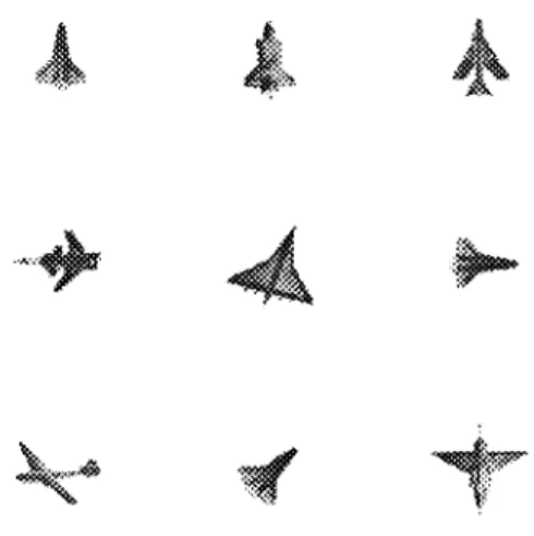
incorporating a carrier frequency into the filter. The targets used in most of the
experiments of this paper are shown in Fig. 1. The filters were designed to recognize
the
three space shuttles with different orientation in positions 1, 6 and 8 of the figure
(counting from left to right and from top to bottom).
We have compared unipolar [0,1] and bipolar [1, -1] filters3 and have found that both
yield good response equivalent to the pure phase -only filter: the bipolar filter has a
diffraction efficiency of 40% and a space- bandwidth product (SBWP) of 3L, whereas the
unipolar filter has a diffraction efficiency of 10% and a SBWP of 4L.
Optical Pattern Recognition /
6 7m a y n o t s o fa r b e im p le m e n te d a s m a tc h e d filte rs , b u t w e m e n tio n th e m fo r th e s a k e o f c o m p le te n e ss . M o m e n t m e th o d s a re d e s c rib e d in a n o th e r p a p e r.
4 )
Other methods
in c lu d e a ll m e th o d s th a t d o n o t fa ll in th e p re c e d in g th re e g ro u p s . T h e y in c lu d e m e th o d s s u c h a s c o o rd in a te tra n s fo rm a tio n m e th o d s .phase-only filters
P h a s e -o n ly filte rs h a v e b e e n s h o w n to y ie ld s h a rp c o rre la tio n p e a k s a n d lo w s id e lo b e s , in a d d itio n to im p ro v in g filte r d is c rim in a tio n . S in c e C irc u la r h a rm o n ic filte rs te n d to h a v e la rg e s id e lo b e s , fa b ric a tin g th e filte rs a s p h a s e -o n ly C H C filte rs c a n b e e x p e c te d to im p ro v e p e rfo rm a n c e .
T h e p h a s e -o n ly C H C filte r is
h m (P ) = e x p [ ja m (p ) + m < |>] (5 ) w h e re a m (p ) + m <t> is th e p h a s e o f th e F o u rie r tra n s fo rm o f th e C H C c o m p o n e n t o f o rd e r m . H o w e v e r th is filte r is n o t ro ta tio n in v a ria n t, b e c a u s e th e c e n te r c o rre la tio n o f th e filte r w ith th e o b je c t fro m w h ic h th e filte r, w h ic h is e q u a l to
C , •* |F m (p )|p d p e x p (jm < j)o )
Jo
(
6
)
w h e re < po is th e ro ta tio n a n g le o f th e ta rg e t, b e c o m e s fo r a re a l filte r C m - 2 7 1 |F m (r)|rd r c o s m fp (7 )w h ic h c h a n g e s w ith ro ta tio n a n g le <J>0- T h is m a y b e a lle v ia te d b y u s in g tw o filte rs , a c o s in e filte r a n d a s in e filte r, b u t th is re q u ire s a n o p tic a l s y ste m a b le to c o m b in e tw o b e a m s , w h ic h is le s s c o n v e n ie n t.2
A s in g le b in a ry p h a se -o n ly filte r (B P O F ) c a n b e m a d e in v a ria n t to ta rg e t ro ta tio n b y in c o rp o ra tin g a c a rrie r fre q u e n c y in to th e filte r. T h e ta rg e ts u s e d in m o s t o f th e e x p e rim e n ts o f th is p a p e r a re s h o w n in F ig . 1 . T h e filte rs w e re d e s ig n e d to re c o g n iz e th e th re e s p a c e s h u ttle s w ith d iffe re n t o rie n ta tio n in p o s itio n s 1 , 6 a n d 8 o f th e fig u re (c o u n tin g fro m le ft to rig h t a n d fro m to p to b o tto m ).
W e h a v e c o m p a re d u n ip o la r [0 ,1 ] a n d b ip o la r [1 ,-1 ] filte rs2 a n d h a v e fo u n d th a t b o th y ie ld g o o d re sp o n s e e q u iv a le n t to th e p u re p h a s e -o n ly filte r: th e b ip o la r filte r h a s a d iffra c tio n e ffic ie n c y o f 4 0 % a n d a s p a c e -b a n d w id th p ro d u c t (S B W P ) o f 3 L , w h e re a s th e u n ip o la r filte r h a s a d iffra c tio n e ffic ie n c y o f 1 0 % a n d a S B W P o f 4 L .
ovs-Figure 1: Targets used for recognition experiments.
covariance filter
The filter described next is the result of the combination of two ideas: the CHC
rotation -invariant filter and a sidelobe- reducing composite filter. Because the aim of this
filter is to eliminate the contribution to the correlation of the mean of the target, we call
this filter a covariance filter.4
The equation which describes this filter, in the simplified specific case where there is
one object to be recognized and one to be discriminated against, is
h(x,y) = af(x,y) + bg(x,y) + cu(x,y)
(8)
where a, b and c are real coefficients to be determined. The function f(x,y) is the object
to be recognized, g(x,y) is to be rejected and u(x,y) is a uniform background with a size
equal to or greater than f(x,y). Usually, the function u(x,y) is a rectangle, but in rotation
invariant filters more complex shapes must be used because a uniform object does not
have a CHC decomposition except for the zero order. The values of the constants a, b
and c are determined by solving a set of linear equations for x = y = 0
R fh(0,0) = aRff(0,0) + bRfg(0,0) + cRfu(0,0) = Rff(0,0)
(9)
Rgh(0,0) = aRgf(0,0) + bRgg(0,0) + cRgu(0,0) = 0
(10)
F ig u r e 1 : T a rg e ts u s e d fo r re c o g n itio n e x p e rim e n ts.
covariance filter
T h e filte r d e s c rib e d n e x t is th e re su lt o f th e c o m b in a tio n o f tw o id e a s : th e C H C ro ta tio n -in v a ria n t filte r a n d a s id e lo b e -re d u c in g c o m p o site filte r. B e c a u s e th e a im o f th is filte r is to e lim in a te th e c o n trib u tio n to th e c o rre la tio n o f th e m e a n o f th e ta rg e t, w e c a ll th is filte r a c o v a ria n c e filte r.4
T h e e q u a tio n w h ic h d e s c rib e s th is filte r, in th e s im p lifie d s p e c ific c a s e w h e re th e re is o n e o b je c t to b e re c o g n iz e d a n d o n e to b e d isc rim in a te d a g a in s t, is
h (x ,y ) = a f(x ,y ) + b g (x ,y ) + c u (x ,y ) (8 )
w h e re a , b a n d c a re re a l c o e ffic ie n ts to b e d e te rm in e d . T h e fu n c tio n f(x ,y ) is th e o b je c t to b e re c o g n iz e d , g (x ,y ) is to b e re je c te d a n d u (x ,y ) is a u n ifo rm b a c k g ro u n d w ith a s iz e e q u a l to o r g re a te r th a n f(x ,y ). U s u a lly , th e fu n c tio n u (x ,y ) is a re c ta n g le , b u t in ro ta tio n in v a ria n t filte rs m o re c o m p le x s h a p e s m u s t b e u s e d b e c a u se a u n ifo rm o b je c t d o e s n o t h a v e a C H C d e c o m p o s itio n e x c e p t fo r th e z e ro o rd e r. T h e v a lu e s o f th e c o n s ta n ts a , b a n d c a re d e te rm in e d b y s o lv in g a s e t o f lin e a r e q u a tio n s fo r x = y = 0
R fh (0 ,0 ) = a R ff(0 ,0 ) + b R fg (O .O ) + c R fu (0 ,0 ) = R ff(0 ,0 ) (9 )
Optical Pattern Recognition / 69
Ruh(0,0) = aRuf(0,0) + bRug(0,0) + cRuu(0,0) = 0
(11)
where Rfh(0,0), Rgh(0,0), Ruh(0,0) are respectively the cross -correlation of f(x,y) and
h(x,y), g(x,y) and h(x,y) and u(x,y) and h(x,y) at the point (0,0) and where Rff(0,0),
Rgg(0,0) and Ruu(0,0) are respectively the autocorrelations of the functions f(x,y) and
g(x,y) at the point (0,0).
From Eq. (10), g(x,y) is completely rejected by the filter h(x,y). But in many
practical cases, the clutter and unwanted objects present in the input scene are unknown
a priori. The g(x,y) may therefore not be available for filter design. The composite
filter becomes simply
h(x,y) = f(x,y) + au(x,y)
(12)
To ensure that the correlation center IRff(0,0)12 be a maximum in the output plane, the
center used for the CH expansion should be a proper center of the object f(x,y). A
rotation invariant covariance filter, which adds rotation invariance to the above filter, is
a composite CH filter
hm(r,O) _ [f11(r) + aum(r)] exp(jm6)
(13)
which is a linear combination of the CH component fm(r,0)= fm(r)exp(jm0) of the f(x,y)
and a constant CH function um(r)exp(jm6) with
K
when
R1 <_ r <_ R2
um(r) =
0
when
0 <_r<R1
(14)
where K is a complex constant, R2 is the radius of the CH filter fm(r,O) and R1 is the
radius of a small circle inside which um(r) is equal to zero. The value of R1 is
determined experimentally. There exists an infinity of objects whose CH functions are
equal to um(r) described by Eq. (13). One possibility is illustrated in the Fig. 2.
Optical Pattern Recognition /
6 9R u h (0 ,0 ) = a R u f(0 ,0 ) + b R u g (0 ,0 ) + c R u u (0 ,0 ) = 0 (1 1 )
w h e re R fh (0 ,0 ), R g h (0 ,0 ), R u h (0 ,0 ) a re re s p e c tiv e ly th e c ro ss -c o rre la tio n o f f(x ,y ) a n d h (x ,y ), g (x ,y ) a n d h (x ,y ) a n d u (x ,y ) a n d h (x ,y ) a t th e p o in t (0 ,0 ) a n d w h e re R ff(0 ,0 ), R g g (O .O ) a n d R u u (0 ,0 ) a re re sp e c tiv e ly th e a u to c o rre la tio n s o f th e fu n c tio n s f(x ,y ) a n d g (x ,y ) a t th e p o in t (0 ,0 ).
F ro m E q . (1 0 ), g (x ,y ) is c o m p le te ly re je c te d b y th e filte r h (x ,y ). B u t in m a n y p ra c tic a l c a s e s, th e c lu tte r a n d u n w a n te d o b je c ts p re se n t in th e in p u t s c e n e a re u n k n o w n a p rio ri. T h e g (x ,y ) m a y th e re fo re n o t b e a v a ila b le fo r filte r d e s ig n . T h e c o m p o site filte r b e c o m e s s im p ly
h (x ,y ) = f(x ,y ) + a u ( x ,y ) (1 2 ) T o e n s u re th a t th e c o rre la tio n c e n te r IR ff(0 ,0 )l2 b e a m a x im u m in th e o u tp u t p la n e , th e c e n te r u s e d fo r th e C H e x p a n s io n s h o u ld b e a p ro p e r c e n te r o f th e o b je c t f(x ,y ). A ro ta tio n in v a ria n t c o v a ria n c e filte r, w h ic h a d d s ro ta tio n in v a ria n c e to th e a b o v e filte r, is a c o m p o s ite C H filte r
h m (r,0 ) = [fm (r) + a u m (r)] e x p (jm 0 ) (1 3 )
w h ic h is a lin e a r c o m b in a tio n o f th e C H c o m p o n e n t fm (r,8 )= fm (r)e x p (jm 9 ) o f th e f(x ,y ) a n d a c o n s ta n t C H fu n c tio n u m (r)e x p (jm 0 ) w ith
' K u m (r) = 0 w h e n w h e n R l < r < R 2 0 < r <
R
i (1 4 ) w h e re K is a c o m p le x c o n s ta n t, R 2 is th e ra d iu s o f th e C H filte r fm (r,0 ) a n d R j is th e ra d iu s o f a s m a ll c irc le in s id e w h ic h u m (r) is e q u a l to z e ro . T h e v a lu e o f R j is d e te rm in e d e x p e rim e n ta lly . T h e re e x ists a n in fin ity o f o b je c ts w h o s e C H fu n c tio n s a re e q u a l to u m (r) d e s c rib e d b y E q . (1 3 ). O n e p o s sib ility is illu s tra te d in th e F ig . 2 .Figure 2. Uniform object (order 2).
The derivation of the binary CH covariance filter is similar to that of the
binary CH filter. The Fourier transform of Eq. (13) is calculated. The amplitude of the
transform is set to unity throughout the Fourier plane. The resulting filter is then
binarized according to Eq. (14) or other. The binary CH covariance filter produces the
required impulse response of a continuous phase -only CH covariance filter.
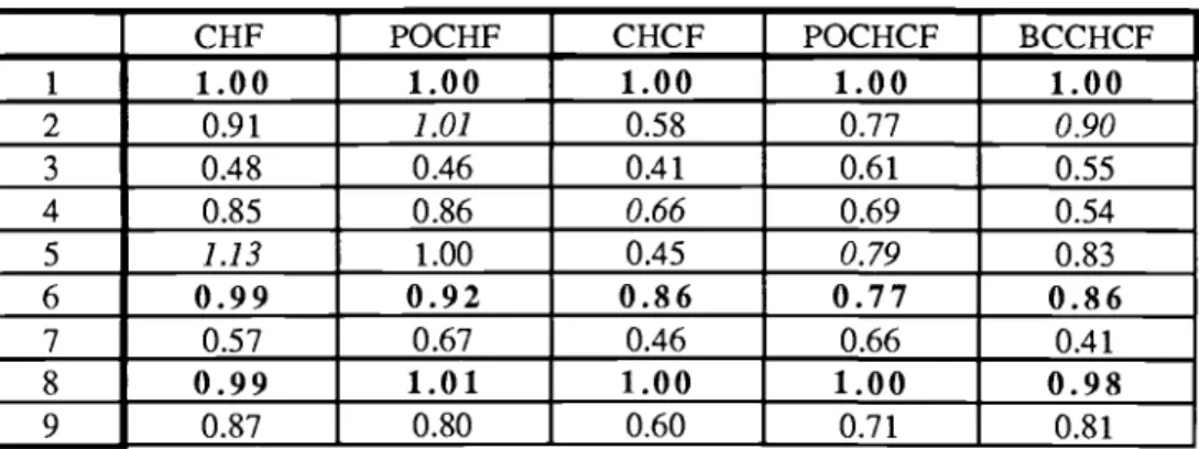
Table 1 shows the correlation peak values obtained by the optical experiments.
Objects 1, 6 and 8 were space shuttles rotated by various angles, and the other numbers
correspons to other aircraft. All the data were normalized by the peak intensity of image
No.l. The filters were made and tested under slightly different conditions so it was
difficult to compare absolute values of the peak intensities from different filters. The
phase -only filters were encoded as CGHs. The binary CH covariance filter is written
directly on photographic film. Their correlation peaks were therefore in the off -axis
diffraction orders.
It is easy to see that the covariance filter gave results that were superior to the others
from the point of view of discrimination ability.
Table 1. Normalized output peak intensities obtained by optical filtering.
CHF
POCHF
CHCF
POCHCF
BCCHCF
11.00
1.00
1.00
1.00
1.00
2
0.91
1.01
0.58
0.77
0.90
30.48
0.46
0.41
0.61
0.55
4
0.85
0.86
0.66
0.69
0.54
51.13
1.00
0.45
0.79
0.83
6
0.99
0.92
0.86
0.77
0.86
70.57
0.67
0.46
0.66
0.41
80.99
1.01
1.00
1.00
0.98
9
0.87
0.80
0.60
0.71
0.81
F ig u r e 2 . U n ifo rm o b je c t (o rd e r 2 ).T h e d e riv a tio n o f th e b in a ry C H c o v a ria n c e filte r is s im ila r to th a t o f th e b in a ry C H filte r. T h e F o u rie r tra n sfo rm o f E q . (1 3 ) is c a lc u la te d . T h e a m p litu d e o f th e tra n s fo rm is s e t to u n ity th ro u g h o u t th e F o u rie r p la n e . T h e re s u ltin g filte r is th e n b in a riz e d a c c o rd in g to E q . (1 4 ) o r o th e r. T h e b in a ry C H c o v a ria n c e filte r p ro d u c e s th e re q u ire d im p u lse re sp o n se o f a c o n tin u o u s p h a s e -o n ly C H c o v a ria n c e filte r.
T a b le 1 s h o w s th e c o rre la tio n p e a k v a lu e s o b ta in e d b y th e o p tic a l e x p e rim e n ts . O b je c ts 1 , 6 a n d 8 w e re s p a c e s h u ttle s ro ta te d b y v a rio u s a n g le s , a n d th e o th e r n u m b e rs c o rre s p o n s to o th e r a irc ra ft. A ll th e d a ta w e re n o rm a liz e d b y th e p e a k in te n s ity o f im a g e N o .l. T h e filte rs w e re m a d e a n d te ste d u n d e r s lig h tly d iffe re n t c o n d itio n s s o it w a s d iffic u lt to c o m p a re a b s o lu te v a lu e s o f th e p e a k in te n sitie s fro m d iffe re n t filte rs . T h e p h a s e -o n ly filte rs w e re e n c o d e d a s C G H s . T h e b in a ry C H c o v a ria n c e filte r is w ritte n d ire c tly o n p h o to g ra p h ic film . T h e ir c o rre la tio n p e a k s w e re th e re fo re in th e o ff-a x is d iffra c tio n o rd e rs .
It is e a sy to s e e th a t th e c o v a ria n c e filte r g a v e re s u lts th a t w e re s u p e rio r to th e o th e rs fro m th e p o in t o f v ie w o f d is c rim in a tio n a b ility .
T a b le 1 . N o rm a liz e d o u tp u t p e a k in te n s itie s o b ta in e d b y o p tic a l filte rin g . C H F P O C H F C H C F P O C H C F B C C H C F 1 1 .0 0 1 .0 0 1 .0 0 1 .0 0 1 .0 0 2 0 .9 1
1.01
0 .5 8 0 .7 70.90
3 0 .4 8 0 .4 6 0 .4 1 0 .6 1 0 .5 5 4 0 .8 5 0 .8 60.66
0 .6 9 0 .5 4 51.13
1 .0 0 0 .4 50.79
0 .8 3 6 0 .9 9 0 .9 2 0 .8 6 0 .7 7 0 .8 6 7 0 .5 7 0 .6 7 0 .4 6 0 .6 6 0 .4 1 8 0 .9 9 1 .0 1 1 .0 0 1 .0 0 0 .9 8 9 0 .8 7 0 .8 0 0 .6 0 0 .7 1 0 .8 1Optical Pattern Recognition / 71
coordinate transformation
An alternative invariant pattern recognition method is to use a coordinate transformation
system. The problem was that existing optical coordinate transforming systems do not
yield very good results, so we decided to develop our own rectangular to polar coordinate
transformation system. The idea we used is to have an array of cells where each cell
redirect the light to a new corresponding cell in the transformed plane. In the first
experiments, we used a periodic array of cells . This was a computer simulation, and it
illustrated one of the problems of coordinate transformations: non -uniform sampling.
The samples in the transform plane were not equally spaced.
So we devised a non -uniform sampling grid that is nonuniform in both the object plane
and in the coordinate -transformed plane, which results in a much more acceptable
sampling. This device is shown in Fig. 3, and the coordinate -transformed samples are
shown on the right.
The device was calculated by computer, and was printed by a high -resolution commercial
laser printer. The device is used by placing it behind an object, and the light from each
elementary cell of the object is diffracted into the corresponding area on the transform
plane. Note that the device is object- independent and can be used for any object. Its
resolution is about 32x32 pixels, but this could be increased by an order of magnitude
using diffractive optics techniques.
v .0 1.ww# w
ríitrr:.e_:a=stï
."I...A .".41..1..1.
Figure 3
Coordinate transformation with a nonuniform sampling grid and its output
The coordinate transformer was then used in the optical system shown in Fig. 4.
Optical Pattern Recognition / 71
coordinate transformation
A n a lte rn a tiv e in v a ria n t p a tte rn re c o g n itio n m e th o d is to u s e a c o o rd in a te tra n s fo rm a tio n s y s te m . T h e p ro b le m w a s th a t e x is tin g o p tic a l c o o rd in a te tra n sfo rm in g s y s te m s d o n o t y ie ld v e ry g o o d re s u lts , s o w e d e c id e d to d e v e lo p o u r o w n re c ta n g u la r to p o la r c o o rd in a te tra n sfo rm a tio n s y s te m . T h e id e a w e u s e d is to h a v e a n a rra y o f c e lls w h e re e a c h c e ll re d ire c t th e lig h t to a n e w c o rre s p o n d in g c e ll in th e tra n s fo rm e d p la n e . In th e firs t e x p e rim e n ts , w e u s e d a p e rio d ic a rra y o f c e lls . T h is w a s a c o m p u te r s im u la tio n , a n d it illu s tra te d o n e o f th e p ro b le m s o f c o o rd in a te tra n s fo rm a tio n s : n o n -u n ifo rm s a m p lin g . T h e s a m p le s in th e tra n s fo rm p la n e w e re n o t e q u a lly s p a c e d .
S o w e d e v is e d a n o n -u n ifo rm s a m p lin g g rid th a t is n o n u n ifo rm in b o th th e o b je c t p la n e a n d in th e c o o rd in a te -tra n sfo rm e d p la n e , w h ic h re su lts in a m u c h m o re a c c e p ta b le s a m p lin g . T h is d e v ic e is s h o w n in F ig . 3 , a n d th e c o o rd in a te -tra n s fo rm e d s a m p le s a re s h o w n o n th e rig h t.
T h e d e v ic e w a s c a lc u la te d b y c o m p u te r, a n d w a s p rin te d b y a h ig h -re so lu tio n c o m m e rc ia l la se r p rin te r. T h e d e v ic e is u s e d b y p la c in g it b e h in d a n o b je c t, a n d th e lig h t fro m e a c h e le m e n ta ry c e ll o f th e o b je c t is d iffra c te d in to th e c o rre s p o n d in g a re a o n th e tra n sfo rm p la n e . N o te th a t th e d e v ic e is o b je c t-in d e p e n d e n t a n d c a n b e u s e d fo r a n y o b je c t. Its re so lu tio n is a b o u t 3 2 x 3 2 p ix e ls , b u t th is c o u ld b e in c re a s e d b y a n o rd e r o f m a g n itu d e u s in g d iffra c tiv e o p tic s te c h n iq u e s.
MUMi
muwm
mmom
F ig u re 3
C o o rd in a te tra n s fo rm a tio n w ith a n o n u n ifo rm s a m p lin g g rid a n d its o u tp u t
T h e c o o rd in a te tra n s fo rm e r w a s th e n u s e d in th e o p tic a l s y s te m s h o w n in F ig . 4 .
He -Ne
laser
beam
CCD
P1MAC
-I
computer
L10
argon laser
beam
LCLV
CGH
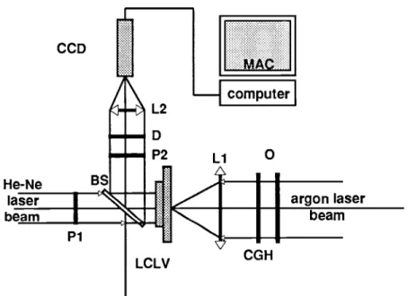
Figure 4: Coordinate transforming pattern classification system
The Object O on the right is transilluminated by an argon laser, and the coordinate
-transformed pattern appears on the liquid -crystal light valve (LCLV); the He -Ne laser
beam from the left gathers the information on the LCLV and Fourier transforms the
pattern by means of lens L2. P1 and P2 are crossed polarizers required to transform the
polarization -coded output of the LCLV into amplitude variations.A CCD camera then
inputs the Fourier data into a computer for classification.
Although the system was successfully used for invariant recognition, we found that
better results were used if a cylindrical lens was used for L2 instead of a spherical lens.
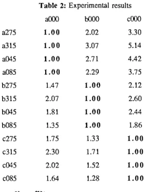
Table 2 shows some of the results obtained for the three letters A, B, and C using a
cylindrical lens.
The numbers in the left -hand column correspond tothe orientations of the letters; the
other numbers correspond to the normalized differences between the measured results, so
larger values correspond to larger differences. A value of one in the table means that
there was no difference measured between the input object and the unrotated input object.
Perfect recognition would mean that all the rotated values for one object would yield
ones, and the table shows that this is indeed the case. In addition, there were no false
alarms, since all the cross -values are larger than 1.33. Experiments using more letters
were also carried out with similar results. For letters that are difficult to discriminate
such as L and I, more refined techniques will have to be used than the simple difference
method used here.
computer
He-Ne
argon laser
laser
beam
beam
LCLV
F ig u r e 4 : C o o rd in a te tra n s fo rm in g p a tte rn c la ss ific a tio n s y s te m
T h e O b je c t O o n th e rig h t is tra n s illu m in a te d b y a n a rg o n la se r, a n d th e c o o rd in a te - tra n s fo rm e d p a tte rn a p p e a rs o n th e liq u id -c ry s ta l lig h t v a lv e (L C L V ); th e H e -N e la se r b e a m fro m th e le ft g a th e rs th e in fo rm a tio n o n th e L C L V a n d F o u rie r tra n s fo rm s th e p a tte rn b y m e a n s o f le n s L 2. P i a n d P 2 a re c ro s se d p o la riz e rs re q u ire d to tra n s fo rm th e p o la riz a tio n -c o d e d o u tp u t o f th e L C L V in to a m p litu d e v a ria tio n s .A C C D c a m e ra th e n in p u ts th e F o u rie r d a ta in to a c o m p u te r fo r c la ss ific a tio n .
A lth o u g h th e s y s te m w a s s u c c e s s fu lly u s e d fo r in v a ria n t re c o g n itio n , w e fo u n d th a t b e tte r re su lts w e re u s e d if a c y lin d ric a l le n s w a s u s e d fo r L 2 in s te a d o f a s p h e ric a l le n s . T a b le 2 s h o w s s o m e o f th e re s u lts o b ta in e d fo r th e th re e le tte rs A , B , a n d C u s in g a c y lin d ric a l le n s .
T h e n u m b e rs in th e le ft-h a n d c o lu m n c o rre s p o n d to th e o rie n ta tio n s o f th e le tte rs ; th e o th e r n u m b e rs c o rre s p o n d to th e n o rm a liz e d d iffe re n c e s b e tw e e n th e m e a s u re d re s u lts , s o la rg e r v a lu e s c o rre s p o n d to la rg e r d iffe re n c e s . A v a lu e o f o n e in th e ta b le m e a n s th a t th e re w a s n o d iffe re n c e m e a su re d b e tw e e n th e in p u t o b je c t a n d th e u n ro ta te d in p u t o b je c t. P e rfe c t re c o g n itio n w o u ld m e a n th a t a ll th e ro ta te d v a lu e s fo r o n e o b je c t w o u ld y ie ld o n e s, a n d th e ta b le s h o w s th a t th is is in d e e d th e c a s e . In a d d itio n , th e re w e re n o fa lse a la rm s , s in c e a ll th e c ro ss -v a lu e s a re la rg e r th a n 1 .3 3 . E x p e rim e n ts u s in g m o re le tte rs w e re a lso c a rrie d o u t w ith s im ila r re su lts. F o r le tte rs th a t a re d iffic u lt to d is c rim in a te s u c h a s L a n d I, m o re re fin e d te c h n iq u e s w ill h a v e to b e u s e d th a n th e s im p le d iffe re n c e m e th o d u s e d h e re .
Optical Pattern Recognition / 73
Table 2: Experimental results
a000
b000
c000
a275
1.00
2.02
3.30
a315
1.00
3.07
5.14
a045
1.00
2.71
4.42
a085
1.00
2.29
3.75
b275
1.47
1.00
2.12
b315
2.07
1.00
2.60
b045
1.81
1.00
2.44
b085
1.35
1.00
1.86
c275
1.75
1.33
1.00
c315
2.30
1.71
1.00
c045
2.02
1.52
1.00
c085
1.64
1.28
1.00
Circular sampling filter
Another rotation invariant system using a coding somewhat similar to the previous
coordinate transformation system is shown in Fig. 5.
A grating is coded onto concentric circular rings so the light from each ring is diffracted
in a different direction. The light from each ring is then focused onto a different element
of an array of points; each point corresponds to the total intensity of the light going
through one ring. The object or its Fourier transform is put before the device. The
device performs an operation similar to a ring -wedge detector, but without the need for
any electronics except for a detector array at the point array (we used a CCD camera).
The ensemble of intensities of the array of points is characteristic of the object, and is
invariant under rotation of the object.After we built this system, we found that a similar
system had been proposed by Casasent et al.; 5 however these authors had only shown
the diffraction pattern used, and had not studied their capability for pattern classification.
Figure 5. Circular sampling filter
Optical Pattern Recognition /
7 3T a b le 2 : E x p e rim e n ta l re s u lts aO O O b O O O cO O O a 2 7 5 1 .0 0 2 .0 2 3 .3 0 a 3 1 5 1 .0 0 3 .0 7 5 .1 4 a 0 4 5 1 .0 0 2 .7 1 4 .4 2 a 0 8 5 1 .0 0 2 .2 9 3 .7 5 b 2 7 5 1 .4 7 1 .0 0 2 .1 2 b 3 1 5 2 .0 7 1 .0 0 2 .6 0 b 0 4 5 1 .8 1 1 .0 0 2 .4 4 b 0 8 5 1 .3 5 1 .0 0 1 .8 6 c 2 7 5 1 .7 5 1 .3 3 1 .0 0 c 3 1 5 2 .3 0 1 .7 1 1 .0 0 c 0 4 5 2 .0 2 1 .5 2 1 .0 0 c 0 8 5 1 .6 4 1 .2 8 1 .0 0
Circular sampling filter
A n o th e r ro ta tio n in v a ria n t s y s te m u s in g a c o d in g s o m e w h a t s im ila r to th e p re v io u s c o o rd in a te tra n s fo rm a tio n s y s te m is s h o w n in F ig . 5 .
A g ra tin g is c o d e d o n to c o n c e n tric c irc u la r rin g s s o th e lig h t fro m e a c h rin g is d iffra c te d in a d iffe re n t d ire c tio n . T h e lig h t fro m e a c h rin g is th e n fo c u se d o n to a d iffe re n t e le m e n t o f a n a rra y o f p o in ts ; e a c h p o in t c o rre s p o n d s to th e to ta l in te n sity o f th e lig h t g o in g th ro u g h o n e rin g . T h e o b je c t o r its F o u rie r tra n s fo rm is p u t b e fo re th e d e v ic e . T h e d e v ic e p e rfo rm s a n o p e ra tio n s im ila r to a rin g -w e d g e d e te c to r, b u t w ith o u t th e n e e d fo r a n y e le c tro n ic s e x c e p t fo r a d e te c to r a rra y a t th e p o in t a rra y (w e u s e d a C C D c a m e ra ). T h e e n s e m b le o f in te n s itie s o f th e a rra y o f p o in ts is c h a ra c te ris tic o f th e o b je c t, a n d is in v a ria n t u n d e r ro ta tio n o f th e o b je c t.A fte r w e b u ilt th is s y ste m , w e fo u n d th a t a s im ila r s y s te m h a d b e e n p ro p o s e d b y C a sa se n t e t a l.; 5 h o w e v e r th e se a u th o rs h a d o n ly s h o w n th e d iffra c tio n p a tte rn u s e d , a n d h a d n o t s tu d ie d th e ir c a p a b ility fo r p a tte rn c la ss ific a tio n .
F ig u r e 5 . C irc u la r s a m p lin g filte r
the Fourier transform is put before the device instead of the object itself. They had
proposed using a liquid -crystal light valve in a manner similar to Fig. 4 to generate
parallel light, but had not implemented it. In our experiments, we did this and obtained
god results slightly better than those of Table 1.
M -r image
In all the methods using Circular harmonic components previously used, only the
information from a restricted set of CHC components is used. We have devised a method
that uses all the information from all the CHC components.
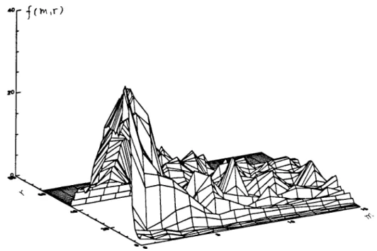
First it is necessary to generate what we call the m -r image of the object: imagine all
the 1- dimensional CHC components set side -to -side in order of increasing order m. This
is represented in Fig. 6 as a 3 -D plot, where one axis is the radius r, and the other is the
CHC order m. The object used was a space shuttle.
Now if this plot is correlated with the m -r image corresponding to an unknown target,
the correlation peak obtained will be invariant under rotation of the target, since each
CHC component has this invariance. But since all the CHC components are used (in
fact we used 32 orders, and because of symmetry, did not use the negative orders), the
correlation will be very selective. The results of correlating the m -r image of the space
shuttle with the 6 other aircraft and a space shuttle rotated by 90 degrees used in the
other experiments are shown in Table 3.
Figure 6. The m -r plot for a space shuttle
th e F o u rie r tra n s fo rm is p u t b e fo re th e d e v ic e in s te a d o f th e o b je c t itse lf. T h e y h a d p ro p o s e d u s in g a liq u id -c ry s ta l lig h t v a lv e in a m a n n e r s im ila r to F ig . 4 to g e n e ra te p a ra lle l lig h t, b u t h a d n o t im p le m e n te d it. In o u r e x p e rim e n ts, w e d id th is a n d o b ta in e d g o d re s u lts s lig h tly b e tte r th a n th o s e o f T a b le 1 .
M-r image
In a ll th e m e th o d s u s in g C irc u la r h a rm o n ic c o m p o n e n ts p re v io u s ly u s e d , o n ly th e in fo rm a tio n fro m a re stric te d s e t o f C H C c o m p o n e n ts is u s e d . W e h a v e d e v is e d a m e th o d th a t u s e s a ll th e in fo rm a tio n fro m a ll th e C H C c o m p o n e n ts .
F irst it is n e c e ss a ry to g e n e ra te w h a t w e c a ll th e m -r im a g e o f th e o b je c t: im a g in e a ll th e 1 -d im e n s io n a l C H C c o m p o n e n ts s e t s id e -to -s id e in o rd e r o f in c re a s in g o rd e r m . T h is is re p re se n te d in F ig . 6 a s a 3 -D p lo t, w h e re o n e a x is is th e ra d iu s r, a n d th e o th e r is th e C H C o rd e r m . T h e o b je c t u s e d w a s a s p a c e s h u ttle .
N o w if th is p lo t is c o rre la te d w ith th e m -r im a g e c o rre s p o n d in g to a n u n k n o w n ta rg e t, th e c o rre la tio n p e a k o b ta in e d w ill b e in v a ria n t u n d e r ro ta tio n o f th e ta rg e t, s in c e e a c h C H C c o m p o n e n t h a s th is in v a ria n c e . B u t s in c e a ll th e C H C c o m p o n e n ts a re u s e d (in fa c t w e u s e d 3 2 o rd e rs, a n d b e c a u se o f s y m m e try , d id n o t u s e th e n e g a tiv e o rd e rs ), th e c o rre la tio n w ill b e v e ry s e le c tiv e . T h e re s u lts o f c o rre la tin g th e m -r im a g e o f th e s p a c e s h u ttle w ith th e 6 o th e r a irc ra ft a n d a s p a c e s h u ttle ro ta te d b y 9 0 d e g re e s u s e d in th e o th e r e x p e rim e n ts a re s h o w n in T a b le 3 .
40
j
f ^ i DOptical Pattern Recognition / 75
Table 3
M -r image correlation results
xf102
xlight
xplan
xsst
Nav090
xx29
xxnavl
-0.0034
0.0744
0.0030
-0.0281
1,000
-0.0087
0.1438
Nav090 represents the rotated space shuttle. the entry xxnavl corresponds to a space
shuttle with the bay doors open, which is considered as a different object because the
filter was not designed to recognize it. The table shows that discrimination is extremely
good. The disadvantage of this method is that the m -r image of every target must be
calculated before carrying out the correlation, which is very time- consuming, but not
necessarily prohibitive. The calculation time for this experiment was 30 seconds on a
Sun Sparcstation 1. We are investigating ways to speed up the process, including the
use of Optics.
Conclusion
We have described some of our recent work in rotation invariant pattern recognition.
Some of the other research carried out in our laboratories and involving mostly invariant
moments is described in a companion paper by Y. Sheng.
The most promising developments in invariant pattern recognition involving CHC
filters involves the use of binary phase only filters, multiple CHC filters and coordinate
-transformation devices. The latter is particularly promising in view of the fact that
diffractive optics technology allowing the fabrication of high -quality coordinate
transforming devices is becoming available. This technology, combined with techniques
described here and in other papers should lead to light, compact and fast invariant pattern
recognition systems.
References
1H. H. Arsenault, L. Leclerc and Y. Sheng, "Similarity and invariance in pattern
recognition," Real -time signal processing for industrial applications, Critical Reviews
of Optical Science and Technology, B. Javidi, Ed., Proc SPIE 960 , 2 -17 (1989).
2 L. Leclerc, Y. Sheng, and H. H. Arsenault, "Rotation- invariant phase -only and binary
phase -only correlation," Appl. Opt. 28, 1251 -1256 (1989).
3L. Leclerc, Y. Sheng and H. H. Arsenault, "Circular harmonic covariance filters for
rotation invariant object recognition and discrimination," Opt. Comm. 85 , 299 -305
(1991).
4H. H. Arsenault, Y. Sheng and J. Bulabois, "Modified composite filter for pattern
recognition in the presence of noise with a non -zero mean," Opt. Comm. 63 , 15 -20
(1987).
5D. Casasent et al., "Diffraction pattern sampling using a computer -generated
hologram, ", Appl. Opt. 6, 983 -989 (1986).
Optical Pattern Recognition /
7 5T a b le 3
M -r im a g e c o rre la tio n re s u lts
x f l 0 2 x l i g h t x p la n x s s t N a v 0 9 0 x x 2 9 x x n a v l -0 .0 0 3 4 0 .0 7 4 4 0 .0 0 3 0 -0 .0 2 8 1 1 ,0 0 0 -0 .0 0 8 7 0 .1 4 3 8 N a v 0 9 0 re p re se n ts th e ro ta te d s p a c e s h u ttle , th e e n try x x n a v l c o rre s p o n d s to a s p a c e s h u ttle w ith th e b a y d o o rs o p e n , w h ic h is c o n sid e re d a s a d iffe re n t o b je c t b e c a u s e th e filte r w a s n o t d e s ig n e d to re c o g n iz e it. T h e ta b le s h o w s th a t d is c rim in a tio n is e x tre m e ly g o o d . T h e d is a d v a n ta g e o f th is m e th o d is th a t th e m -r im a g e o f e v e ry ta rg e t m u st b e c a lc u la te d b e fo re c a rry in g o u t th e c o rre la tio n , w h ic h is v e ry tim e -c o n s u m in g , b u t n o t n e c e s s a rily p ro h ib itiv e . T h e c a lc u la tio n tim e fo r th is e x p e rim e n t w a s 3 0 s e c o n d s o n a S u n S p a rc s ta tio n 1 . W e a re in v e stig a tin g w a y s to s p e e d u p th e p ro c e s s , in c lu d in g th e u s e o f O p tic s .
Conclusion
W e h a v e d e s c rib e d s o m e o f o u r re c e n t w o rk in ro ta tio n in v a ria n t p a tte rn re c o g n itio n . S o m e o f th e o th e r re s e a rc h c a rrie d o u t in o u r la b o ra to rie s a n d in v o lv in g m o s tly in v a ria n t m o m e n ts is d e s c rib e d in a c o m p a n io n p a p e r b y Y . S h e n g .
T h e m o s t p ro m isin g d e v e lo p m e n ts in in v a ria n t p a tte rn re c o g n itio n in v o lv in g C H C filte rs in v o lv e s th e u s e o f b in a ry p h a s e -o n ly filte rs , m u ltip le C H C filte rs a n d c o o rd in a te - tra n s fo rm a tio n d e v ic e s. T h e la tte r is p a rtic u la rly p ro m isin g in v ie w o f th e fa c t th a t d iffra c tiv e o p tic s te c h n o lo g y a llo w in g th e fa b ric a tio n o f h ig h -q u a lity c o o rd in a te tra n s fo rm in g d e v ic e s is b e c o m in g a v a ila b le . T h is te c h n o lo g y , c o m b in e d w ith te c h n iq u e s d e sc rib e d h e re a n d in o th e r p a p e rs s h o u ld le a d to lig h t, c o m p a c t a n d fa s t in v a ria n t p a tte rn re c o g n itio n s y s te m s .
References
1 H . H . A rs e n a u lt, L . L e c le rc a n d Y . S h e n g , “ S im ila rity a n d in v a ria n c e in p a tte rn re c o g n itio n ,”
Real-time signal processing for industrial applications,
C ritic a l R e v ie w s o f O p tic a l S c ie n c e a n d T e c h n o lo g y , B . J a v id i, E d ., P ro c S P IE 9 6 0 ,2 - 1 7 (1 9 8 9 ). 2 L . L e c le rc , Y . S h e n g , a n d H . H . A rs e n a u lt, “ R o ta tio n -in v a ria n t p h a s e -o n ly a n d b in a ry p h a se -o n ly c o rre la tio n ,” A p p l. O p t. 2 8 , 1 2 5 1 -1 2 5 6 (1 9 8 9 ).3 L . L e c le rc , Y . S h e n g a n d H . H . A rs e n a u lt, “ C irc u la r h a rm o n ic c o v a ria n c e filte rs fo r ro ta tio n in v a ria n t o b je c t re c o g n itio n a n d d is c rim in a tio n ,” O p t. C o m m . 8 5 ,2 9 9 - 3 0 5 (1 9 9 1 ).
4 H . H . A rse n a u lt, Y . S h e n g a n d J . B u la b o is , “ M o d ifie d c o m p o s ite filte r fo r p a tte rn re c o g n itio n in th e p re se n c e o f n o is e w ith a n o n -z e ro m e a n ,” O p t. C o m m . 6 3 , 1 5 -2 0 (1 9 8 7 ).
5 D . C a sa s e n t e t a l., “ D iffra c tio n p a tte rn s a m p lin g u s in g a c o m p u te r- g e n e ra te d h o lo g ra m ,” , A p p l. O p t. 6 , 9 8 3 -9 8 9 (1 9 8 6 ).