Diffusional Stability Studies of a T91 / 12Cr-2Si-Fe
Functionally Graded Composite
by
SEAN MORTON
Submitted to the Department of Materials Science and Engineering
in fulfillment of the requirements for the degree of
BACHELOR OF SCIENCE
at the
MASSACHUSETTS INSTITUTE OF TECHNOL
IF.
S-OF TEGHNOLOGY
May 2008
JUN 1.8 2008
@ 2008 Massachusetts Institute of Technology
LIBRARIE
All rights reserved. LIBRARES
MCHNES
Author:
Department of Materials Science and Engineering
May 16, 2008
Certified by:
Ronald G. Ballinger
Professor of Nuclear Science and Engineering &
Materials Science and Engineering
Thesis Supervisor
Accepted by:Caroline A. Ross
Chair, Undergraduate Committee
77 Massachusetts Avenue Cambridge, MA 02139 http://libraries.mit.edu/ask
DISCLAIMER NOTICE
Due to the condition of the original material, there are unavoidable flaws in this reproduction. We have made every effort possible to provide you with the best copy available.
Thank you.
The following pages were not included in the original document submitted to the MIT Libraries. This is the most complete copy available.
Abstract
There is current interest in heavy liquid metal coolant for nuclear fast reactor
applications, though their corrosion of common structural metals has so far limited their development. Currently under research is a composite metal composed of layers of a 12% Cr, 2% Si corrosion resistant iron alloy on a T91 structural layer for containment of liquid lead-bismuth eutectic. The goal of this research is to investigate the solid state diffusion of silicon between the two layers, as removal of silicon from the corrosion resistant layer will reduce or eliminate its effectiveness.
The diffusion process in this system has been characterized and modeled through studies of diffusion couples at elevated temperatures. It has been shown that at an operation temperature of 6500C, this material will be compositionally stable for at least 50 years,
longer than the expected lifetime due to corrosion of the material. Thus, the lifetime of a 12Cr-2Si-Fe / T91 composite is not limited by bulk diffusion of silicon between layers.
Table of Contents
Introduction & Background
Methods
Experimental
Modeling
Results & Discussion
Conclusions
Future Work
References
List of Tables
Table 1: Lead-Bismuth Eutectic Properties
1
Table 2: ASTM A 213 T91 Composition
4
Table 3: Silicon Diffusion Data
5
List of Figures
Figure 1: Fe-Cr Phase Diagram
3
Figure 2: Optical Micrograph of HIP Bonded Interface
8
Figure 3: Comparison of Models
9
Figure 4: Concentration Profiles from Diffusion Couples
10
Figure
5:
Concentration Profile of HIPed Sample, As Received 10
Figure 6: Si Concentration Profile With Model, 300 Hours
11
Figure 7: Si Concentration Profile With Model, 600 Hours
12
Figure 8: Projected Silicon Concentration Profile at
Introduction & Background
The United States Department of Energy has recently been investigating and promoting the development of so-called Generation IV Nuclear Reactors. These are reactor designs developed based on a number of fundamental concepts: that they be inherently safe, produce energy at an economically competitive cost, that they minimize the amount of waste produced, and mitigate concerns of nuclear proliferation. Some of the most promising of these designs are those that incorporate the use of a liquid lead-bismuth eutectic (LBE) mixture as the primary heat exchange fluid.'
Liquid Metal Pb LBE Bi Na
Atomic Number 82 - 83 11
Atomic Weight (amu) 207.2 -208 209.0 23.0
Melting Point ("C) 327.5 125.5 271.4 97.8 Boiling Point (*C) 1750 1670 1564 883 Density (g/cm3 at 600*C) 10.27 9.91 9.66 0.83 Viscosity (cP at 600"C) 1.556 1.170 1.049 0.207 Vapor Pressure (mmHg at 0.0004 NA 0.08723 23.70 600 0C)
Thermal Neutron Cross Section 0.17 0.094 0.034 0.53
(barns)
Chemical Reactivity (with air Inert Inert Inert Highly
and water) . reactive
Table 1: Lead-Bismuth Eutectic Properties.
This design choice has a number of advantages over both standard water systems and other liquid metal systems such as sodium. LBE is inert in air and water, unlike the explosively reactive sodium. It has a low melting point and high boiling point, and
extremely low vapor pressure. The heat capacity is very high, making it ideal for
compact reactor designs. Additionally, the mixture has a very low thermal neutron cross section, which makes it ideal for the primary coolant in a fast reactor due to a low
reaction with the fast neutron flux. The single major drawback to an LBE system is that it is known to be highly corrosive to many common reactor materials. Nickel, zirconium, and aluminum are highly soluble in liquid lead at elevated temperatures, making
austenitic stainless steels, zircalloys, incoloys, and hastelloys - common reactor superalloys - unusable for containment of the liquid.! However, various passivating alloys have been shown to display corrosion resistance to LBE, most notably those that develop chromium oxide or silicon oxide layers. Furthermore, alloys with multiple oxide layers have shown even greater resistance to LBE corrosion.3 Recently, a number of iron alloys containing varying amount of chromium and silicon have been investigated as candidates for a reactor material to contain LBE.2 Corrosion resistance was found to increase with silicon concentration, and increased heavily with chromium concentrations at and above 12% by weight. A composition of 2%wt Si and 12%wt Cr has been chosen as the primary candidate for further research and testing. It is desired that the material remain a single phase alpha-iron (ferrite) system, and it is known that Fe-Cr systems with chromium content much greater than 12%wt will phase separate into alpha and sigma phases, with the sigma phase being a Cr rich phase.5 This phase separation causes lattice
A omic Percent Ci romium 13001 S11004 ,b~12 3 46 2 I.(aFie. Me) S01 00 0 10 20 30 40 60 GG 70 8D 90 t00
Fe Weight Percent Chromium Cr
Figure 1: Fe-Cr Phase Diagram. The delta phase becomes stable at low temperature with
increasing chromium content. Additionally, the gamma phase becomes stable at 846*C with a chromium content of 6.5%. Chromium content was kept low to avoid stability of the delta phase, while heating of samples was kept to 800*C to avoid stability of the gamma phase.6
With respect to silicon, it is known that in an irradiated environment, silicon as an alloying element greatly increases void nucleation and can have deleterious effects on the material in terms of mechanical structure in the presence of radiation.7 In addition, while there is no known published research confirming this, it is believed that alloys will also have greatly increased radiation embrittlement at or above 2.5%wt silicon. These
concerns have limited the choice of silicon concentration to a maximum of 2% by weight. With this choice of a 12Cr-2Si-Fe system, there is another concern that arises. The alloy is weak, as it has contains no strengthening mechanism, and could become embrittled over time as a result of the silicon. Thus, it is proposed that this alloy be used
as a cladding layer on top of T91, a high strength ferritic steel developed for the nuclear industry.8 T91 is ideal as it is also a ferritic steel, and has a fairly similar composition to Fe-12Cr-2Si.
T91 C Mn P S Si Cr Mo V Nb N Al Ni
Composition
ASTM A 213 0.08 0.30 0.020 0.010 0.20 8.00 0.85 0.18 0.06 0.030 0.040 0.40 0.12 0.60 max max 0.50 9.50 1.05 0.25 0.10 0.070 max max
Table 2 - ASTM A 213 T91 Composition. T91 derives its strength from
molybdenum and microalloying with niobium.8
The effectiveness of our proposed composite structure relies heavily on the retention of silicon by the 12Cr-2Si-Fe cladding layer. Bulk diffusion of silicon into the T91 layer will weaken both the strength of the T91 layer and the corrosion resistance of the 12Cr-2Si-Fe layer.
It is the purpose of this research to investigate the diffusion of silicon in this composite system and determine a reasonable life cycle period for our proposed system at operation temperatures that can be expected for a typical generation IV reactor.
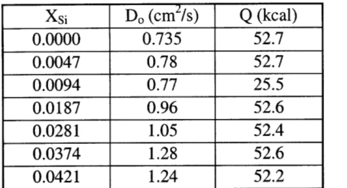
There has been one notable study of the diffusion of silicon in ferritic iron in which an activation energy and Arrhenius coefficients (Do) that vary with silicon concentration were reported.4 These data suggest favorable diffusion characteristics. The reported value of the diffusion activation energy is used here in creating a diffusion model, and the possible effects of a varying Do is investigated through numerical simulation.
Xsi D, (cm2/s)
Q
(kcal) 0.0000 0.735 52.7 0.0047 0.78 52.7 0.0094 0.77 25.5 0.0187 0.96 52.6 0.0281 1.05 52.4 0.0374 1.28 52.6 0.0421 1.24 52.2Table 3: Silicon Diffusion Data. As reported by Borg and Lai, 1970.4
Note that D, varies linearly with the weight fraction of silicon, while the activation energy is constant.
Methods Experimental
Sample billets of T91 and the 12Cr-2Si-Fe alloys were produced by Metalmen, Inc. Samples measuring 1.5 cm x 2.5 cm x 0.5 cm were cut from the billets and cold worked via passes through a rolling mill to at least 20% reduction in area. After cold working, T91 samples were annealed at 10500C for 2 hours, with a temperature ramp (both up and
down) of 1500C per hour. Annealing specifications for AISI 405 stainless steel were used
as a reference for the 12Cr-2Si-Fe due to similar compositions. These samples were annealed at 750*C for 4 hours, with a temperature ramp of 150*C per hour. Samples were then lapped on a polishing wheel to achieve parallel faces. One side was polished to a mirror finish (finished with 1 pm grit polishing paper) with silicon carbide and alumina abrasives.
Various methods were investigated for producing diffusion couples. The desired bond between the materials needed to be free of voids and inclusions to allow free diffusion across the interface, but any significant melting at the interface was undesirable
reliable diffusion data. Cold rolling was attempted in an attempt to best emulate the bond that might be achieved via commercial production of the composite, but proved
unworkable with the available equipment. High pressure compression at elevated
temperatures was attempted again to no avail due to corrosion as a result of poor vacuum. This method is believed tenable if the samples were vacuum canned in stainless steel beforehand. E-beam welding was researched, but was not attempted as size of the melt zone at the interface would be on the same order as the diffusion length scale of silicon. Production of the diffusion couples was ultimately achieved with the commercial process of hot isostatic pressing (HIP). The samples were processed by Ultraclad/Bodycote Inc. via HIP at 1065*C for 4 hours. K-type thermocouples were spot-welded to the samples, which were then vacuum sealed in quartz ampoules by Allen Scientific Glass, Inc. prior to the HIP bonding process.
The sample ampoules were heated at 800*C for 300 and 600 hours, with a temperature ramp of 50*C per hour. The 800*C point was chosen as high as possible to accelerate diffusion in the ferrite (BCC) material, while staying safely below the Al transition point for Fe-12Cr, where austenite (FCC) becomes the stable phase (see Figure
1). Upon removal from the furnace, the samples were cross-sectioned with an abrasive
diamond saw and polished to mirror finish. Linear composition analysis was done with electron microprobe analysis (EMPA) on a JEOL JXA-733 electron microprobe with a
1.2 pim spot size and 100 nA beam current, calibrated to elemental samples of Cr, Mo, Si and Fe.
Modeling & Simulation
Borg and Lai report a diffusion coefficient for silicon in alpha-iron that varies linearly with silicon concentration (see Table 3). This is reflected in the value of the Arrhenius prefactor D.. Modeling of diffusion with a coefficient that varies with concentration cannot be done with the standard error function solution (Eq 2) to the diffusion equation.
A numerical simulator was created to investigate the implications of this varying
diffusivity. The starting point is the diffusion equation, or Fick's Second Law (Eq. 1).
aC
a
2
C
2D Eq.1ataxT
x
C= CS +(C. -C, )-erf(
)
Eq. 24Dt
AC
ACDc
-=
D(C)
X Eq. 3At
Ax
At
ACn
= D(Cn
)
2(C_
- 2Cn
+ C
Eq.
4
(
Ax)
n- +Letting D be a function of concentration, this is turned into a difference equation (Eq. 3) and discretized, solving for ACn. The resulting expression (Eq. 4) is easily implemented in a computer simulation, iterating over a time step At and a distance step of Ax. The diffusion coefficient can now be computed for each point in the simulation as a function of the local concentration. A step function in concentration is used as the initial
77 Massachusetts Avenue Cambridge, MA 02139 http://libraries.mit.edu/ask