HAL Id: hal-00916115
https://hal.inria.fr/hal-00916115
Submitted on 9 Dec 2013
HAL is a multi-disciplinary open access
archive for the deposit and dissemination of
sci-entific research documents, whether they are
pub-lished or not. The documents may come from
teaching and research institutions in France or
abroad, or from public or private research centers.
L’archive ouverte pluridisciplinaire HAL, est
destinée au dépôt et à la diffusion de documents
scientifiques de niveau recherche, publiés ou non,
émanant des établissements d’enseignement et de
recherche français ou étrangers, des laboratoires
publics ou privés.
Component-Based System — A Case Study for the
Industrial World
Nuno Gaspar, Ludovic Henrio, Eric Madelaine
To cite this version:
Nuno Gaspar, Ludovic Henrio, Eric Madelaine. Formally Reasoning on a Reconfigurable
Component-Based System — A Case Study for the Industrial World. The 10th International Symposium on
Formal Aspects of Component Software, Oct 2013, Nanchang, China. �hal-00916115�
Component-Based System —
A Case Study for the Industrial World
Nuno Gaspar1,2,3, Ludovic Henrio2
, and Eric Madelaine1,2
1
INRIA Sophia Antipolis
{Nuno.Gaspar,Eric.Madelaine}@inria.fr
2
Univ. Nice Sophia Antipolis, CNRS, I3S, UMR 7271, 06900 Sophia Antipolis, France [email protected]
3
ActiveEon S.A.S http://www.activeeon.com/
Abstract. The modularity offered by component-based systems made it one of the most employed paradigms in software engineering. Precise structural specification is a key ingredient that enables their verifica-tion and consequently their reliability. This gains special relevance for reconfigurable component-based systems.
To this end, the Grid Component Model (GCM) provides all the means to define such reconfigurable component-based applications. In this paper we report our experience on the formal specification and verification of a reconfigurable GCM application as an industrial case study.
Keywords: Component-based Systems, Autonomous Systems, Formal Methods, Reconfiguration, Model-Checking
1
Introduction
Meeting the demands of our modern society requires special care when designing software. Applications are expected to be full-featured, performant and reliable. Moreover, for distributed applications high-availability is also cause of concern. Taming this complexity makes the use of modular techniques mandatory. To this end, the modularity offered by component-based systems made it one of the most employed paradigms in software engineering.
Embracing this approach enables structural specifications, thus leveraging formal verification. This gains special relevance for reconfigurable component-based systems. Indeed, while offering systems with an higher availability, the ability to evolve at runtime inherently increases the complexity of an application, making its formal verification a challenging task.
1.1 Context
This work occurs in the context of the Spinnaker project, a French collaborative project between INRIA and several industrial partners, where we intend to
con-tribute for the widespread adoption of RFID-based technology. To this end, our contribution comes with the design and implementation of a non-intrusive, flexi-ble and reliaflexi-ble solution that can integrate itself with other already deployed sys-tems. Specifically, we developed the HyperManager, a general purpose moni-toring application with autonomic features. This was built using GCM/ProAc-tive1
— a Java middleware for parallel and distributed programming that follows the principles of the GCM component model. For the purposes of this project,
it had the goal to monitor the E-Connectware2
(ECW) framework in a loosely coupled manner.
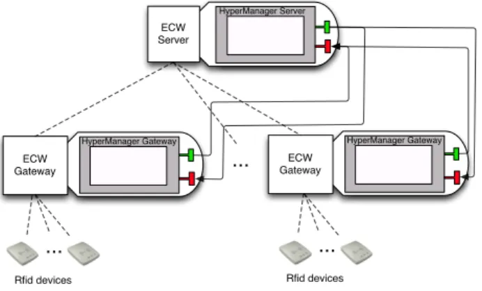
For the sake of clarity let us describe one of the real life scenarios faced in a industrial context. An hotel needs to keep track of the bed sheets used by their customers. Every bed sheet used has an embedded RFID sensor chip that uniquely identifies it. At every shift, the hotel maids go through all the rooms recovering these bed sheets and putting them in a laundry cart. By reaching the end of the rooms’ corridor, the laundry cart emits to another physical device running the ECW Gateway software the bed sheets’ identifiers. For each corridor there might be several laundry carts and one device running the ECW Gateway. After receiving the bed sheets’ identifiers the ECW Gateways emit this informa-tion along with their own identifier to yet another physical device running the ECW Server. Once the information reaches the top of this hierarchy it can be used to whatever purpose, namely bed sheets traceability.
Abstracting away this particular scenario, one can see it in a hierarchical manner as depicted by Figure 1.
... HyperManager Server ECW Server HyperManager Gateway ECW Gateway HyperManager Gateway ECW Gateway ... ... Rfid devices Rfid devices
Fig. 1.Hierarchical representation of our case study
Regarding the previously described scenario, this hierarchical view should pose no doubt. For each of the n floors of the hotel there are m laundry carts that communicate in a one-to-one style with a gateway. On the other hand, the
1
http://proactive.activeeon.com/index.php
2
gateways communicate with the server on a n-to-one style. Moreover, there is also the need to cope for possible maintenance issues. For instance, in the case of malfunction of some device running the ECW Gateway, it may be required to replace it or add a new one in order to avoid any overloading.
The architecture depicted by Figure 1 also includes the HyperManager ap-plication. Indeed, it is deployed alongside the pre-existent distributed system, performing its monitoring on all ECW components. The careful reader will no-tice that the flow of requests go both from the HyperManager Server to the HyperManager Gateway, and vice-versa. Indeed, these follow the pull and push styles of communication, respectively. More details regarding these mechanisms will be discussed at a later stage.
1.2 Contributions
This paper discusses an industrial case study of a reconfigurable monitoring application. On the one hand, it should be noted that we aim at real-life appli-cations, indeed, our models go upto the intricacies of the middleware itself. This has the direct consequence of promoting the use of formal methods within the industry.
On the other hand, we go beyond previous work [5] by including reconfigu-ration capabilities. This yields bigger state-spaces and inherently new issues to deal with. Investigating the feasibility of such undertakings is within the scope of this paper too. To the best of our knowledge this is the first work address-ing the challenges of behavioural specification and verification of reconfigurable component-based applications.
1.3 Organisation of the Paper
The remaining of this paper is organised as follows. Section 2 gives the main in-gredients of our behavioural semantics for specifying GCM applications. Then, Section 3 presents our general purpose monitoring application — The
Hyper-Manager. Section 4 details its simplified behavioural model, i.e. without
sup-port for structural reconfigurations, and its proven properties. The impact of adding reconfiguration capabilities is discussed in Section 5. Related work is discussed in Section 6. For last, Section 7 concludes this paper.
2
A Behavioural Semantics for GCM Applications
This section provides a brief overview of the behavioural semantics modelling GCM/ProActive applications by relying on the pNets formalism. For the sake of space we omit some of the underlying definitions. For a detailed account of its intricacies the interested reader is pointed to [1].
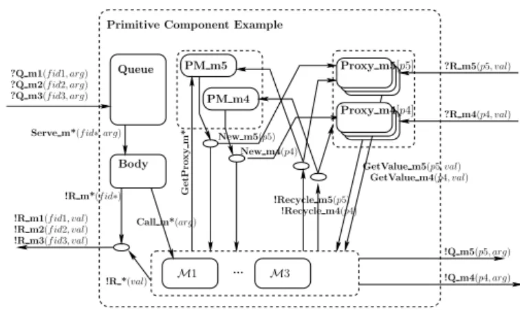
As an illustrative example, the internals of a GCM primitive component
featuring three service methods — m1, m2 and m3 — and two client methods
Primitive Component Example
M1 M3
!Recycle m5(p5) !Recycle m4(p4)
GetValue m4(p4, val) Serve m*(f id∗, arg)
Queue PM m5 PM m4 Body ... Call m*(arg) !R m1(f id1, val) !R m2(f id2, val) !R m3(f id3, val) !R m*(f id∗) !R *(val) ?Q m3(f id3, arg) ?Q m2(f id2, arg)
?Q m1(f id1, arg) ?R m5(p5, val) ?R m4(p4, val) !Q m5(p5, arg) !Q m4(p4, arg) GetValue m5(p5, val) New m5(p5) G e tP ro x y m * New m4(p4) Proxy m4[p4] Proxy m5[p5]
Fig. 2.pNet representing a primitive component
Invocation on service methods — Q mi, i∈{1,2,3} — go through a Queue, that
dispatches the request — Serve m* — to the Body. Serving the request consists
in performing a Call m* to the adequate service method, represented by the Mi
boxes in the figure. Once a result is computed, a synchronized R m* action is emitted. This synchronization occurring between the service method and the Body stems from the fact that GCM primitive components are mono-threaded.
Moreover, the careful reader will notice the f idi, i∈{1,2,3} in the figure. These
are called futures and act as promises for replies, leveraging asynchrony between components.
Service methods interact with external components by means of client
in-terfaces. This requires obtaining a proxy — GetProxy m*, New mi, i∈{4,5} —
in order to be able to invoke client methods — Q mi, i∈{4,5}. The reply —
R mi, i∈{4,5} — goes to the proxy used to call the external component. Then,
a GetValue mi, i∈{4,5} is performed in order to access the result in the method
being served. Finally, Recycle mi, i∈{4,5} actions can be performed in order to
release the proxies.
The behaviour of the Queue and the Body elements should pose no doubt. The former acts as priority queue with a First in, First Out (FIFO) policy, raising an exception if its capacity is exceeded. The latter dispatches the requests to the appropriate method and awaits its return, thus preventing the service of other requests in parallel.
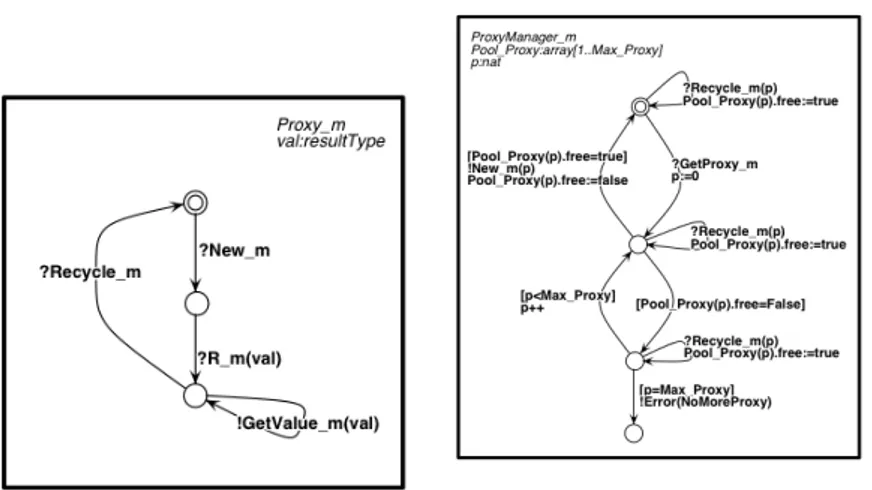
The handling of proxies however, is not as straightforward and deserves a closer look. Figures 3 and 4 illustrate the behaviour of the Proxies and Proxy
Managers, respectively. Upon reception of a New mi action, a Proxy waits for
the reply of the method invoked with it — R m —, making thereafter its result available — GetValue m. The proxy becomes then available on the reception of a Recycle m action.
The behaviour of the Proxy Manager is slightly more elaborated. This main-tains a pool of proxies, keeping track of those available and those already
al-Fig. 3.Behaviour of proxy
Fig. 4. Behaviour of the proxy manager
located. On the reception of a GetProxy m action, it activates a new proxy — New m — if there is one available. Should that not be the case, an Er-ror(NoMoreProxy) action is emitted. As expected, a Recycle m action frees a previously allocated proxy.
3
The HyperManager
The HyperManager is a general purpose monitoring application that was
developed in the context of the Spinnaker project3
. The goal was to deliver a modular solution that would be capable of monitoring a distributed application and react to certain events. As such, the HyperManager is itself a distributed application, deployed alongside the target application to monitor.
Generally, when performing a monitoring task in an application one may consider two types of events: pull and push. The former stands for the usual communication scenario where the request comes from the client and then re-sponded by the server. The latter however, is when the server pushes data to clients independently from a client’s request. Both styles of communication are employed in the HyperManager application.
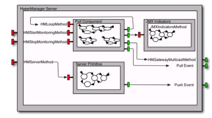
As illustrated by Figure 5, the server (composite) component of the
Hyper-Managerapplication features three primitive components that are responsible
for the application logic. Each possesses one or several service methods that stand for their functionalities and are modelled by labelled transition systems (LTSs).
The JMX Indicators component features only one service method: it accepts
requests about a particular JMX4
indicator and replies its status. This encap-sulates business code and interacts directly with ECW.
3
Project OSEO ISIS. http://www.spinnaker-rfid.com/
4
HyperManager Server HMStartMonitoringMethod HMStopMonitoringMethod HMGatewayMulticastMethod Pull Component JMXIndicatorsMethod JMX Indicators Server Primitive HMServerMethod Push Event HMLoopMethod Pull Event
Fig. 5.HyperManager server component
The Pull Component however, includes three service methods and four client interfaces. As the component’s name indicates, it is responsible for pulling infor-mation and emitting it as pull events. The service methods HMStartMonitoring-Method and HMStopMonitoringHMStartMonitoring-Method are responsible for starting and stopping the pulling activity, respectively. Typically, these are the methods called by the administrator. The remaining service method, HMLoopMethod, may pose some doubt. Indeed, it is called from one of its own client’s interface. Being a
ProAc-tiveapplication, it follows the active object paradigm where explicit threading is
discouraged. As such, making a method loop is achieved by making this method sending itself a request before concluding its execution.
While in the monitoring loop, the HMLoopMethod method pulls information regarding its own local JMX indicators and those of its gateways via a
multi-cast client interface. The last remaining client interface serves the purpose of
reporting the pulled information as pull events.
Last, the Server Primitive component receives push information from the HM Gateways — typically to alert the occurrence of some anomaly — and emits it as
push events. In our implementation both push and pull events are then displayed
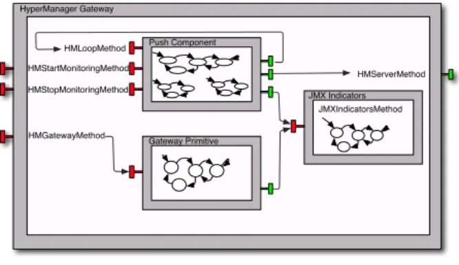
in some application with a graphical interface for administration purposes. The description of the HyperManager’s gateway component follow the same spirit. Figure 6 depicts its constitution.
It is also composed by three primitive components. As expected, the JMX Indicators component has the same semantics as described above.
The Push Component features the same service methods as the Pull Compo-nent. Its semantics however, are slightly different. While looping it will check for the status of its JMX indicators, and communicate with the HyperManager server if some anomaly is encountered — which will then trigger a push event.
As for the Gateway Primitive component, its sole purpose is to reply to the
.. HyperManager Gateway HMStartMonitoringMethod HMStopMonitoringMethod Push Component JMXIndicatorsMethod JMX Indicators Gateway Primitive HMGatewayMethod HMLoopMethod HMServerMethod
Fig. 6.HyperManager gateway component
4
HyperManager’s Behavioural Model
Modelling the HyperManager in the behavioural semantics pNets [1] requires us to provide a behaviour for each service method. In the following we illustrate this by providing an user-version LTS for all of them — i.e. we omit all the machinery involving futures and proxies. Moreover, for more material on this
case study the reader is invited to its companion website5
.
Regarding our modelling and verification workflow, we build the behavioural models by encoding the involved processes in the Fiacre specification language [3]. Then, the flac compiler translates it to Lotos [4]. From there we can use the CADP toolbox [9]. Typically, we use bcg open for state-space generation — in conjunction with distributor if performing it on a distributed setting —, svl scripts for managing state-space replication, label renaming and build products of transition systems. For last, evaluator4 for model-checking the state-space against MCL (Model Checking Language) [13] formulas — an extension of the alternation-free regular µ-calculus with facilities for manipulating data.
To optimize the size of the model, the composite components have no request queue and requests are directly forwarded to the targeted primitive component. This has no influence in the system’s semantics as the primitives’ request queues are sufficient for dealing with asynchrony and requests from the sub-components are directly dispatched too. Moreover, we set the primitive components with re-entrant calls with a queue of size 2, and the remaining of size 1.
4.1 The HM Gateway
The JMX Indicators primitive component only features one service method: JMXIndi-catorsMethod. Its behaviour is modelled by Figure 7. For the sake of simplicity, we only model two types of indicators: MemoryUsage and DeviceStatus. The lat-ter takes into account an identifier, returning its availability status. This relates
5
to the status of a RFID reader transmitting to the ECW Gateway. While the former simply returns the stability status of the memory.
s_mem s_init Call_JMXIndicatorsMethod ? Memory_Usage s_dev Call_JMXIndicatorsMethod ? DeviceStatus(id) R_JMXIndicatorsMethod ! memory_usage(Stable) R_JMXIndicatorsMethod ! memory_usage(Unstable) R_JMXIndicatorsMethod ! device_status(Available, id) R_JMXIndicatorsMethod ! device_status(Unavailable, id)
Fig. 7.Behaviour of the JMXIndicatorsMethod
s1 s_init Call_GatewayMethod ? args s1 Q_JMXIndicatorsMethod ! args s2 GetValue_JMXIndicatorsMethod ? reply R_GatewayMethod ! jmx_reply
Fig. 8.Behaviour of the HMGate-wayMethod
The service method offered by the Gateway Primitive component has also a fairly simple behaviour. It is illustrated by Figure 8. It acts merely as a request forwarder for the JMX Indicators component.
Regarding the Push Component, the HMStartMethod and HMStopMethod methods enable/disable the looping process. This is achieved by a shared variable among processes that acts as a flag. Invoking HMStartMethod will set the flag variable started to true and perform an invocation to HMLoopMethod. On the other hand, HMStopMethod will set the flag to false. Their behaviour is rather trivial and therefore omitted for the sake of space. In practice, the involved labels are GuardQuery, GuardReply?b:bool, SetFalse and SetTrue; their meaning should be obvious from their names.
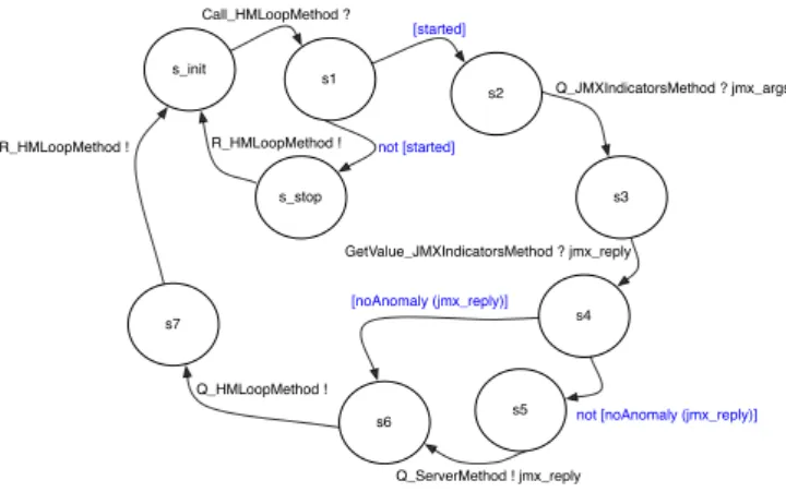
The last remaining service method to describe is the most interesting one — the loop method.
s2 s1 s_init Call_HMLoopMethod ? R_HMLoopMethod ! [started] s_stop not [started] s3 Q_JMXIndicatorsMethod ? jmx_args s4 GetValue_JMXIndicatorsMethod ? jmx_reply s7 R_HMLoopMethod ! [noAnomaly (jmx_reply)]
not [noAnomaly (jmx_reply)]
s5 s6
Q_ServerMethod ! jmx_reply Q_HMLoopMethod !
As illustrated by Figure 9, the actual looping only occurs if the flag variable
startedis set to true, otherwise a simple return without performing any
signif-icant action is made.6
While looping, the JMX indicators are checked. Should an anomaly be detected a report is made to the HM Server. Last, before returning a request is sent to itself — Q HMLoopMethod — in order to be able to continue
looping while the flag variable evaluates to true.
Model Generation and Proven Properties Table 1 illustrates the relevant
information concerning the HM Gateway’s state-space built using the CADP toolbox. The model is generated with two RFID readers.
States Transitions File Size hmgateway.bcg 14.931.628 147.485.103 ∼ 295 mb hmgateway-min.bcg14.931.628 147.485.103 ∼ 296 mb
Table 1.Numbers regarding the gateway model
The entry suffixed by -min means that minimization by branching
bisimu-lation was applied. We note that the minimization process fails to produce a
reduced transition system. This is due to the fact that we do not hide any
com-munication action and all transitions are visible7
. However, there is an increase in the file size even though the number of states and transitions remained equal. This is justified by the fact that bcg min inserts information in the produced file stating that it came from a minimization process. In any case, this overhead is rather negligible.
Having this state-space generated we can now prove some properties regard-ing the expected behaviour of the model. Specifyregard-ing properties of interest in MCL is a rather intuitive task due to its expressiveness and conciseness. Its main ingredients include patterns extracting data values from LTS actions, modali-ties on transition sequences described using extended regular expressions and programming language constructs.
For instance, one could wonder about this rather unusual looping mechanism. Once setting the flag to true — accomplished by Q HMStartMethod —, the
looping continues until a request to stop monitoring is received. That is, there
is no path in which the flag evaluates to false without the occurrence of a Q HMStopMethod.
Property 1. [ "Q_HMStartMethod" . "Q_HMLoopMethod" . (not "Q_HMLoopMethod")* . "GuardReply !FALSE" ] false
6
For the sake of clarity, communications actions are written in black, while local computations are written in blue. Their intended meaning should pose no doubt.
7
It is worth noticing that the flac compiler translates shared variables and internal communications into τ -transitions. These will therefore disappear from the LTS if subject to minimization.
Naturally, we also want to avoid overloading the HM Server with unnecessary messages. As such, we want to ensure that we cannot push data if not in the presence of an anomaly. This can be modelled as follows:
Property 2.
[ ((not "R_JMXIndicatorsMethod !memory_usage (Unstable)")* . "Q_ServerMethod.*") |
((not "R_JMXIndicatorsMethod !device_status ((Unavailable, IdTwo))")* . "Q_ServerMethod.*") |
((not "R_JMXIndicatorsMethod !device_status ((Unavailable, IdOne))")* . "Q_ServerMethod.*")
] false
Both properties are naturally proved true.
4.2 The HM Server
Similarly as seen for the HM Gateway component, the HM Server component also features a JMX Indicators primitive component. This however, is naturally not endowed with indicators for the RFID devices statuses. Technically, we attach to the LTS modelling its behaviour (Figure 7) a context that constraints its requests. Moreover, HMStartMethod and HMStopMethod methods exhibit the same behaviour as described above.
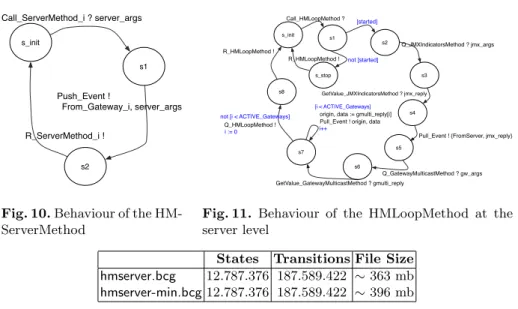
As seen above, upon detection of an anomaly, the HM Gateway component
pushes the relevant information to the HM Server. Then, it is emitted as a push
event as depicted by Figure 10. The careful reader will notice that the emit-ted event also contains the information regarding the HM Gateway from which the anomaly originated. This should come as no surprise as there can be sev-eral of them, and properly identifying the source of an abnormal situation is of paramount importance.
As depicted by Figure 11, the looping process for the HM Server proceeds in a similar fashion as the one from the HM Gateway: the flag variable started’s valuation determines whether we enter the looping process or if we just return. While looping we pull information from the local JMX indicators and emit it as a pull event.
Moreover, via a multicast interface information is pulled from the connected gateways. This, will emit as many pull events as the number of connected gate-ways. Last, a request to itself is performed in order to continue looping.
Model Generation and Proven Properties Table 2 illustrates the relevant
information concerning HM Server’s state-space.
As in the case of the HM Gateway model, the minimization process failed to produce a smaller state-space. However, this time we get a 9% increase in the
s1 s_init Call_ServerMethod_i ? server_args s2 Push_Event ! From_Gateway_i, server_args R_ServerMethod_i !
Fig. 10.Behaviour of the HM-ServerMethod s2 s1 s_init Call_HMLoopMethod ? R_HMLoopMethod ! [started] s_stop not [started] s3 Q_JMXIndicatorsMethod ? jmx_args s4 GetValue_JMXIndicatorsMethod ? jmx_reply s5
Pull_Event ! {FromServer, jmx_reply}
s6
Q_GatewayMulticastMethod ? gw_args GetValue_GatewayMulticastMethod ? gmulti_reply
s7
[i < ACTIVE_Gateways]
Pull_Event ! origin, data
i++ s8 Q_HMLoopMethod ! R_HMLoopMethod ! not [i < ACTIVE_Gateways] i := 0
origin, data := gmulti_reply[i]
Fig. 11. Behaviour of the HMLoopMethod at the server level
States Transitions File Size hmserver.bcg 12.787.376 187.589.422 ∼ 363 mb hmserver-min.bcg12.787.376 187.589.422 ∼ 396 mb
Table 2.Numbers regarding the server model
file size, not so much negligible as the increase noticed for the HM Gateway’s
state-space.8
A rather trivial property we can expect to hold is that we can reach a state which explodes one of the request queues. This can be modelled in MCL as follows:
Property 3. < true* . ’QueueException_ServerPrimitive !.*’> true As mentioned above, we omitted all the machinery involving proxies while describing the service methods’ behaviour. However, this is naturally included in the generated model. For instance, the HMLoopMethod method needs to request a proxy in order to be able to invoke JMX Indicators’s service method. This is naturally encoded as follows:
Property 4. [ (not "GetProxy_JMXIndicatorsMethod.*")* . "Q_JMXIndicatorsMethod.*"] false
As expected, both properties hold in the model.
4.3 System Product, Model Generation and Proven Properties
We attempted to generate a system product constituted by two HM Gateways and one HM Server components. However, even on a machine with 90 GB of RAM, we experienced the so common state-space explosion phenomena.
8
In fact, we encountered another peculiar situation where minimization pro-duced a smaller state-space, yet a bigger file size: http://cadp.forumotion.com/ t374-bcg-file-size-after-minimization
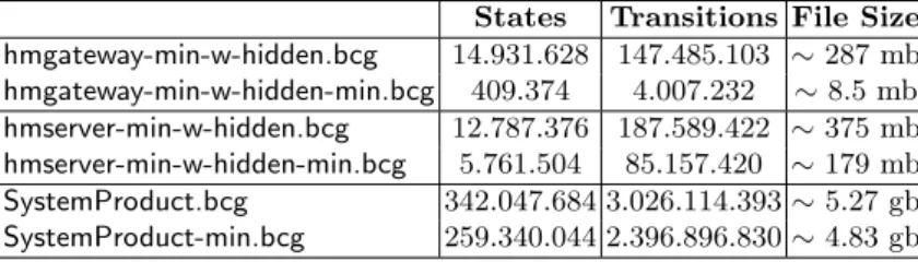
This arises often in the analysis of complex systems. To this end,
commu-nication hiding comes as an efficient and pragmatic approach for tackling this
issue. Indeed, it allows to specify the communication actions that need not to be observed for verification purposes, thus yielding more tractable state-spaces. Table 3 illustrates the effects of applying this technique to the model. The sole communication actions being hidden are the ones involved in (1) the request transmission from the Queue to the adequate method — Serve and Call —, (2) the proxy machinery —GetProxy , New and Recycle —, and (3) finally in the
guard of the looping methods — GuardQuery, GuardReply, SetFalse and SetTrue.
States Transitions File Size hmgateway-min-w-hidden.bcg 14.931.628 147.485.103 ∼ 287 mb hmgateway-min-w-hidden-min.bcg 409.374 4.007.232 ∼ 8.5 mb hmserver-min-w-hidden.bcg 12.787.376 187.589.422 ∼ 375 mb hmserver-min-w-hidden-min.bcg 5.761.504 85.157.420 ∼ 179 mb SystemProduct.bcg 342.047.684 3.026.114.393 ∼ 5.27 gb SystemProduct-min.bcg 259.340.044 2.396.896.830 ∼ 4.83 gb
Table 3.Relevant numbers regarding the generated model
The lines suffixed by -hidden indicate the results obtained by hiding the mentioned communication actions in the minimized HM Gateway and HM server state-spaces. For both, no effect is noticed on the size of the LTS. However, there is a decrease in the file size. This is due to the fact that the hiding process yields several τ -transitions, which facilitates file compression. This has the consequence of leveraging the subsequent minimization process. Indeed, we even obtain a reduction by two orders of magnitude (!) for the HM Gateway state-space.
The HyperManager comes as a monitoring application that should be able to properly trace the origin of an anomaly. As such, one behavioural property that we expect to hold is that whenever an abnormal situation is detected by a HM Gateway, it is fairly inevitable to be reported as a push event that correctly identifies its origin.
First, we shall use MCL’s macro capabilities to help us build the formula:
macro GETVALUE_1_MEMORY () =
"GetValue_JMXIndicatorsMethod_Push_1 !memory_usage (Unstable)" end_macro
macro PUSH_1_MEMORY () =
("Push_Event (FirstGateway, UnstableMemoryUsage)") end_macro
...
The above macros should be self-explanatory. The former represents the detec-tion of an anomaly coming from the first HM Gateway — the model is instan-tiated with two HM Gateways, thus we differentiate their actions by suffixing
them adequately. The latter stands for the emission of the push event corre-sponding to that anomaly. The macros for the remaining relevant actions are defined analogously.
Moreover, we define the following macro generically encoding the fair
in-evitability that after an anomaly the system emits a push.
macro FAIRLY_INEVITABLY_A_PUSH (ANOMALY, PUSH) = [ true* . "ANOMALY" . (not "PUSH")* ]
< (not PUSH)* . PUSH > true end_macro
Having the macros defined, we can now write the formula of interest:
Property 5.
(FAIRLY_INEVITABLY_A_PUSH(GETVALUE_1_MEMORY, PUSH_1_MEMORY) and FAIRLY_INEVITABLY_A_PUSH(GETVALUE_2_MEMORY, PUSH_2_MEMORY) and FAIRLY_INEVITABLY_A_PUSH(GETVALUE_1_DEVICE_1, PUSH_1_DEVICE_1) and FAIRLY_INEVITABLY_A_PUSH(GETVALUE_1_DEVICE_2, PUSH_1_DEVICE_2) and FAIRLY_INEVITABLY_A_PUSH(GETVALUE_2_DEVICE_1, PUSH_2_DEVICE_1) and FAIRLY_INEVITABLY_A_PUSH(GETVALUE_2_DEVICE_2, PUSH_2_DEVICE_2) )
As expected, this property holds for the model.
5
The Case Study Reloaded: On Structural
Reconfigurations
As seen so far, the HyperManager acts as a monitoring application with two styles of communication: pull and push. However, it also needs to cope with structural reconfigurations. This means that at runtime the architecture of the application can evolve by, say, establishing new bindings and/or removing existing ones.
For GCM applications bind and unbind operations are handled by the com-ponent owning the client interface that is supposed to be reconfigurable. This should come as no surprise, indeed, it follows the same spirit as in object-oriented languages: an object holds the reference to a target object; it is this object that must change the reference it holds.
In our case-study, these reconfigurations can occur both at the server level — when pulling data from the bound gateways —, and at gateway level — when pushing data to the server. The difference lies at the fact that the server communicates via a multicast interface, unlike the gateways that establish a standard 1-to-1 communication. Therefore, these are dealt in a different manner.
5.1 HM Reconfigurable Gateway
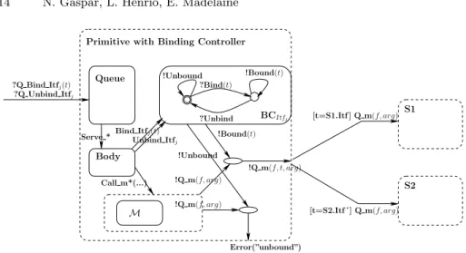
Let us first illustrate how a singleton client reconfigurable interface is modelled in pNets. As depicted by Figure 12, for each client reconfigurable interface there exists a binding controller.
Primitive with Binding Controller M Queue !Q m(f, t, arg) [t=S1.Itf ] Q m(f, arg) [t=S2.Itf´] Q m(f, arg) Body !Q m(f, arg) !Bound(t) Error(”unbound”) BCItfj !Unbound !Bound(t) ?Unbind Call m*(...) !Unbound Bind Itfj(t) S2 S1 ?Q Bind Itfj(t) ?Q Unbind Itfj !Q m(f, arg) Serve * Unbind Itfj
?Bind(t)
Fig. 12.Binding controller
Indeed, we allow for reconfigurations by defining two new request messages for the binding and unbinding of interfaces. These are delegated to a binding controller that upon method invocation over these reconfigurable interfaces will check if they are indeed bound, emitting an error if it is not the case. Moreover, the target of the invocation is decided by checking its passed reference. For this reason one must know statically what are the possible target interfaces that a reconfigurable interface can be bound too.
In practice, to the HM Gateway model discussed in Subsection 4.1 we add the request messages Q Bind ServerMethod and Q Unbind ServerMethod. Since we only have one reconfigurable interface we can avoid adding an explicit pa-rameter — unlike shown in Figure 12, where we demonstrate a more general case. Moreover, since the gateways can only be bound to one target — the server — the binding controller only needs to keep a state variable regarding its connectedness.
As expected, these changes have a considerable impact in the size of the model. This is illustrated by Table 4.
States Transitions File Size hmgateway-reconfig.bcg 354.252.868 4.178.400.886 ∼ 8.45 gb hmgateway-reconfig-min.bcg354.104.012 4.176.956.686 ∼ 8.54 gb
Table 4.Gateway with reconfigurable interface
All the properties proven in Subsection 4.1 still hold for this new HM Gateway model, with a natural overhead in model-checking them in a much bigger state-space. However, for this new model we are more interested in addressing the
reconfiguration capabilities. For instance, provided that the interface is bound, it will not yield an Unbound action upon method invocation.
Property 6.
< true* . "Q_Bind_ServerMethod" . (not "Q_Unbind_ServerMethod")* . "Q_ServerMethod" . (not "Q_Unbind_ServerMethod")* . "Unbound" > true
The above property is proved false. This indicates that provided that the inter-face is bound, a path yielding an Unbound action without the occurrence of a Q Unbind ServerMethod will not occur.
5.2 HM Reconfigurable Server
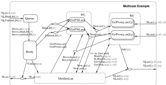
As an illustrative example, the pNet of a primitive component featuring a
re-configurable client multicast interface and two service methods — m1and m2—
is depicted by Figure 13. Multicast Example GrPM m1 GrPM m2 Method m GrProxy m1[p] New m1(p) New m2(p) !R m(f, val) GetProxy m1 GetProxy m2 ?R m1((p, id), val) ?R m2((p, id), val) !R m(val) ?Q Unbind Itfj(t) ?Q m(f, arg) ?Q Bind Itfj(t) Bind Itfj(t) Unbind Itfj(t) !Q m1(p, arg) !Q m2(p, arg) !Q m1(p, G, arg) !Q m2(p, G, arg) GrProxy m2[p] !MC(G) New m1(p, G) New m2(p, G) Recycle m2(p) Recycle m1(p) ∀min {m1,m2} WaitN m(p, n) R WaitN m(p, vect) GetNth m(p, n, val) GetValue m(p, vect) Serve unbind Itfj(t)
Serve bind Itfj(t) Serve m(f, arg)
Itfj Itfj
Body Queue
!Call m(arg)
Fig. 13.pNet example for reconfigurable multicast interface
In short, the machinery involved for dealing with this kind of interfaces mainly differs from reconfigurable singleton interfaces in that we must keep track of the
target’s connectedness status. Indeed, the emission of a new proxy — New mi,i∈{1,2}
— is synchronized in a similar manner, however we also transmit the current status of the multicast interface (i.e. the G variable in the figure). This status will
be taken into account when invoking one of the client methods — Q mi,i∈{1,2}.
In practice, G is a boolean vector whose element’s valuation determine the in-terface’s connectedness.
Table 5 demonstrates the impact of adding reconfiguration capabilities to the HM Server model.
States Transitions File Size hmserver-reconfig.bcg931.640.080 16.435.355.306 ∼ 32.93 gb
Table 5.Server with reconfigurable multicast interface
The generated state-space for the HM Server model nearly attained 1 billion states.9
Our attempts to minimize it revealed to be unsuccessful due to the lack of memory. These were carried out on a workstation with ∼90 GB of RAM.
It is worth noticing that while we were not able to minimize the produced state-space, we were still able to model-check it against the same properties discussed in Subsection 4.2.
5.3 Model Generation and Proven Properties
As seen in Subsection 4.3, building the product of the system already showed to be delicate. Abstraction techniques such as communication hiding were already required to build the system. Thus, it should come as no surprise that we face the same situation here.
However, it should be noted that the hiding process itself, produced little effect on the file size, and no effect on the state-spaces. It mainly acted as a means to leverage the subsequent minimization process, allowing for a very significant state-space reduction. Table 6 illustrates the results obtained by following the same approach as above.
States Transitions File Size hmgateway-reconfig-min-w-hidden.bcg 354.104.012 4.176.956.686 ∼ 8.15 gb hmgateway-reconfig-min-w-hidden-min.bcg 11.090.974 127.799.874 ∼ 283.5 mb hmserver-reconfig-min-w-hidden.bcg 931.640.080 16.435.355.306 ∼ 31.28 gb Table 6.Relevant numbers regarding the generated model with reconfigurable inter-faces
We obtained a significant state-space reduction for the HM Gateway model, but we were unable to minimize the HM Server. Indeed, communication hiding may leverage state-space reduction, but still requires that the minimization pro-cess is able to run, therefore not solving the lack of memory issue. This is a rather
9
As mentioned in Subsection 4.2, for the HM Server model, the JMX Indicators com-ponent is generated with a context not including the request of device statuses. Pre-vious experiments not considering this context produced a HM Server model with the following characteristics: 4.148.563.680 states, with 74.268.977.628 transitions, on a 154.2 GB file. It is interesting to note the huge impact that (the lack of) a contextual state-space generation on one of its components can provoke.
embarrassing situation as we would expect a significant state-space reduction as well for the HM Server.
While communication hiding revealed to be a valuable tool, minimization is still a bottleneck if the input state-space is already too big. Thus, we need to shift this burden to the lower levels of the hierarchy. Indeed, both HM Server and HM Gateway components are the result of a product between their primitive components. Moreover, these are themselves the result of a product between their internals – request queue, body, proxies ...
Table 7 illustrates the results obtained by hiding the same communication actions as in the above approaches, but before starting to build any product.
States Transitions File Size hidden-hmgateway-reconfig.bcg 3.483.000 43.193.346 ∼ 85.46 mb hidden-hmgateway-reconfig-min.bcg 3.073.108 39.373.968 ∼ 83.95 mb hidden-hmserver-reconfig.bcg 210.121.904 3.890.791.694 ∼ 7.52 gb hidden-hmserver-reconfig-min.bcg 177.604.848 3.288.937.718 ∼ 6.61 gb SystemProduct-reconfig.bcg 3.054.464.649 38.680.270.695 ∼ 74.16 gb Table 7.Relevant numbers regarding the generated model with reconfigurable inter-faces
Indeed, following this approach proved to be fruitful as we were able to generate the system product. Yet, minimization remained still out of reach. Nevertheless, we are still in a position to model-check some properties of interest. For instance, pulling information via a multicast emission is now predicated with a boolean array whose element’s valuation determines its connectedness. As an example, a rather simple liveness property is the following one:
Property 7.
<true* . "Q_GatewayMulticastMethod !ARRAY(FALSE FALSE) !MemoryUsage"> true
Initially, both HM Gateways are bound, the above property tell us that we can indeed unbind both of them.
6
Related Work
The maturity attained by the CADP toolbox made it a reference tool among the formal methods community. Several case studies have been published, namely industrial ones addressing other goals than verification. For instance, in [8] Coste et. al. discuss performance evaluation for systems and networks on chips. More closely related with our work we must refer the experiments presented in [7]. A dynamic reconfiguration protocol is specified and model-checked, however their focus is on the reconfiguration protocol itself rather than reconfigurable appli-cations.
Indeed, many works can be found in the literature embracing a behavioural semantics approach for the specification and verification of distributed systems. Yet, literature addressing the aspects of reconfigurable applications remains scarce.
Nevertheless, we must cite the work around BIP (Behaviour, Interaction, Pri-ority) [2] — a framework encompassing rigorous design principles. It allows the description of the coordination between components in a layered way. Moreover, it has the particularity of also permitting the generation of code from its models. Yet, structural reconfigurations are not supported.
Another rather different approach that we must refer is the one followed by tools specifically tailored for architectural specifications. For instance, in [11] Inverardi et. al. discusses CHARMY, a framework for designing and validating architectural specifications. It offers a full featured graphical interface with the goal of being more user friendly in an industrial context. Still, architectural specifications remain of static nature.
Looking at the interactive theorem proving arena we can also find some re-lated material. In [6] Boyer et. al. propose a reconfiguration protocol and prove its correctness in the Coq Proof Assistant [15]. This work however, focuses on the protocol itself, and not in the behaviour of a reconfigurable application. More-over, in [10] we presented Mefresa — a Mechanized Framework for Reasoning on Software Architectures. This work discusses a formal specification and a (re)configuration language for GCM architectures. All the involved machinery and underlying formal semantics are mechanized in Coq. However, at the cur-rent stage of development its main focus is on the reasoning at the architectural level.
7
Final Remarks
In the realm of component-based systems, behavioural specification is among the most employed approaches for the rigorous design of applications. It lever-ages the use of model-checking techniques, by far the most widespread formal method in the industry. Yet, verification in the presence of structural reconfig-urations remains still a rather unaddressed topic. This can be justified by the inherent complexity that such systems impose. However, reconfiguration plays a significant role for the increase in systems availability, and is a key ingredient in the autonomic computing arena, thus tackling its demands should be seen of paramount importance.
In this paper we discussed the specification and formal verification of a re-configurable monitoring application as an industrial case study. Several lessons can be drawn from this work.
The Spinnaker project gave us the opportunity to promote the use of formal methods within the industry. As expected, the interaction with our industrial partners revealed to be a demanding task. Common budgetary issues (time allo-cation, hirings, ...) of such projects and lack of prior formal methods’ exposure by our partners were some of the barriers to overcome. This was further
ag-gravated by the fact that software development was playing a little part in the overall project budget, and therefore not a main priority.
Nevertheless our experience revealed to be fruitful. We were able to witness the general curiosity on the use of formal methods by the industry, and increase our understanding on the needs and obstacles for its broader adoption. Indeed, collaborative projects of this nature allow the industry to test the waters and expose researchers to real-world scenarios. However, bridging the gap between the industry’s expectation and the current state of the art still remains as a challenge for the research community. To this end, recent work on Vercors [12] aims at bringing intuitive specification languages and graphical tools for the non-specialists.
Concerning our task at hand, modelling the HyperManager application upto the intricacies of the middleware led us to a combinatorial explosion in the number of states. This, is further exasperated by the inclusion of reconfigurable interfaces. Even the use of compositional and contextual state-space generation techniques revealed to be insufficient. While this could be solved by further increasing the available memory in our workstation, it is worth noticing that this approach is not always feasible in practice. This bottleneck can be alleviated by performing the synchronization product in a distributed manner. Alas, this is not supported by the CADP toolbox. Alternatively, CADP supports tau-reduction algorithms that reduce on-the-fly the existent τ -transitions. While this approach was successfully applied in [5], its practical effects for this case
study remain as future work.10
Moreover, handling such big state-spaces teaches us the importance of automation regarding model generation. Indeed, debugging can be a daunting task due to the inherent complexity and size of the involved models. Regarding this issue we must refer that we plan on tackling behavioural specification concerns within the Mefresa framework as future work. This will leverage the use of deductive reasoning in a usual model-checking context as demonstrated in [14], and thus relax the burden of dealing with huge state-spaces.
At last, as usual in the realm of formal verification, we conclude that ab-straction is the key. Taking advantage of CADP’s facilities for communication hiding, one can specify actions that need not to be observed for the verification purposes, which further enhances the effects of a subsequent minimization by branching bisimulation. This illustrates the pragmatic rationale of formal verifi-cation by model-checking — the most likely reason behind its acceptance in the industry.
Acknowledgements
The authors are grateful to Fr´ed´eric Lang from the INRIA Vasy team for trou-bleshooting with the CADP toolbox and the semantics of the Fiacre specification
10
It is worth mentioning that the immediate concerns and goals for this case study were more aimed at convincing our industrial partners on the ease of use of our verification workflow.
language. Moreover, our ing´enieur experts Arthur Mbonyinshuti and Bartlomiej Szejna deserve a mention for technical assistance regarding CADP’s license man-agement and the implementation of The HyperManager, respectively.
References
1. Rab´ea Ameur-Boulifa, Ludovic Henrio, Eric Madelaine, and Alexandra Savu. Be-havioural Semantics for Asynchronous Components. RR RR-8167, December 2012. 2. A. Basu, S. Bensalem, M. Bozga, J. Combaz, M. Jaber, T.-H. Nguyen, and J. Sifakis. Rigorous component-based system design using the bip framework. IEEE Software, 28(3):41–48, 2011.
3. B. Berthomieu, J.P. Bodeveix, M. Filali, H. Garavel, F. Lang, F. Peres, R. Saad, J. Stoecker, and F. Vernadat. The syntax and semantics of FIACRE. RR, 2009. 4. Tommaso Bolognesi and Ed Brinksma. Introduction to the iso specification
lan-guage lotos. Comput. Netw. ISDN Syst., 14(1):25–59, March 1987.
5. Rab´ea Ameur Boulifa, Raluca Halalai, Ludovic Henrio, and Eric Madelaine. Veri-fying safety of fault-tolerant distributed components. In International Symposium on Formal Aspects of Component Software (FACS 2011), 2011.
6. Fabienne Boyer, Olivier Gruber, and Damien Pous. Robust reconfigurations of component assemblies. In Proceedings of the 2013 International Conference on Software Engineering, ICSE ’13. IEEE Press, 2013.
7. Manuel Aguilar Cornejo, Hubert Garavel, Radu Mateescu, and Noel De Palma. Specification and verification of a dynamic reconfiguration protocol for agent-based applications. In Krzysztof Zielinski, Kurt Geihs, and Aleksander Laurentowski, editors, DAIS, volume 198 of IFIP Conference Proceedings, pages 229–244. Kluwer, 2001.
8. Nicolas Coste, Holger Hermanns, Etienne Lantreibecq, and Wendelin Serwe. To-wards performance prediction of compositional models in industrial gals designs. In CAV, Lecture Notes in Computer Science, pages 204–218. Springer, 2009. 9. Hubert Garavel, Fr´ed´eric Lang, Radu Mateescu, and Wendelin Serwe. CADP 2010:
A Toolbox for the Construction and Analysis of Distributed Processes. In Tools and Algorithms for the Construction and Analysis of Systems - TACAS 2011. 10. Nuno Gaspar, Ludovic Henrio, and Eric Madelaine. Bringing Coq Into the World
of GCM Distributed Applications. International Journal of Parallel Programming, 2013. HLPP’2013 Special Issue.
11. P. Inverardi, H. Muccini, and P. Pelliccione. Charmy: An extensible tool for archi-tectural analysis. In ESEC-FSE’05, ACM SIGSOFT Symposium on the Founda-tions of Software Engineering. Research Tool Demos, September 5-9, 2005. 12. Oleksandra Kulankhina. A graphical specification environment for GCM
component-based applications. Ubinet master internship report, INRIA, 2013. 13. Radu Mateescu and Damien Thivolle. A model checking language for concurrent
value-passing systems. In Proceedings of the 15th international symposium on Formal Methods, FM ’08, pages 148–164, Berlin, Heidelberg, 2008. Springer-Verlag. 14. Christoph Sprenger. A verified model checker for the modal mu-calculus in coq.
In In TACAS, volume 1384 of LNCS. Springer Verlag, 1998.