HAL Id: hal-02467126
https://hal.inria.fr/hal-02467126
Submitted on 4 Feb 2020
HAL is a multi-disciplinary open access
archive for the deposit and dissemination of
sci-entific research documents, whether they are
pub-lished or not. The documents may come from
teaching and research institutions in France or
abroad, or from public or private research centers.
L’archive ouverte pluridisciplinaire HAL, est
destinée au dépôt et à la diffusion de documents
scientifiques de niveau recherche, publiés ou non,
émanant des établissements d’enseignement et de
recherche français ou étrangers, des laboratoires
publics ou privés.
Sliding Mode Control of Automatic Guidance of Farm
Vehicles in the Presence of Sliding
F Hao, R. Lenain, B. Thuilot, Philippe Martinet
To cite this version:
F Hao, R. Lenain, B. Thuilot, Philippe Martinet. Sliding Mode Control of Automatic Guidance of
Farm Vehicles in the Presence of Sliding. International Symposium on Robotics and Automation,
ISRA’04, Aug 2004, Queretaro, Mexico. pp.582-587. �hal-02467126�
Sliding Mode Control of Automatic Guidance of Farm Vehicles in
the Presence of Sliding
F. Hao, R. Lenain, B. Thuilot, P. Martinet
LASMEA
24, av. des Landais
63177 Aubiere Cedex France
hao@lasmea.univ-bpclermont.fr
Abstract— Satisfactory results of automatic guidance of
farm vehicles have been achieved in previous works as long as vehicles move without sliding, but unfortunately in agricultural applications, sliding always occurs inevitably which causes loss of accuracy. In this paper the problem of path following control of autonomous farm vehicles subject to sliding is addressed. To take sliding effects into account, a vehicle-oriented kinematic model is built in which sliding effects are integrated in the form of additive disturbances to the ideal kinematic model. By transforming the vehicle-oriented kinematic model into a perturbed chained system, a sliding mode controller, which is robust not only to the sliding effects but also to the input noise, is designed with the help of the natural algebraic structure of chained systems. Simulation results show that the proposed control law can guarantee high path-following accuracy even in the presence of sliding.
I. INTRODUCTION
High-precision auto-farming and precise automatic guid-ance of agricultural vehicles have been the subject of research for a long time, since autonomous farm vehicles have some benefits
• Human factors such as the driver’s ability to see
the ground, driver comfort and operator safety do not need to consider when designing vehicles, so the manufacture cost may be reduced.
• Remove human operators from a tired uncomfortable
working environment.
• Vehicles can run at a particular speed which guarantees
the tracking accuracy without constraints of operator factors, increasing production efficiency.
Recently with the development of GPS technology, more and more researchers apply GPS to automatic guidance systems of agricultural vehicles, since GPS can provide realtime absolute position with a centimeter accuracy and outdoor working environment of agricultural vehicles is suitable for using GPS. In our previous works we have solved the problem of curved path following with unique RTK GPS [1], the vehicle kinematic model is built under the assumption of pure rolling, a nonlinear controller guarantee-ing high lateral and orientation accuracy has been designed by converting the kinematic model into a chained system, Kalman filter is used to reconstruct system states only from GPS information, satisfactory results of path following have
been obtained in [1] providing the vehicle moves without sliding. However due to various effects such as slipping of tires, deformability or flexibility of wheels, the conditions of pure rolling without sliding are never strictly satisfied, especially when vehicles move on a slippery ground or on a slope following a curved path, sliding inevitably occurs which deteriorates performances of the automatic guidance and even system stability.
Abundance of satisfactory results of path following con-trol have been achieved as long as there is no sliding between vehicles and ground, but there are very few papers dealing with sliding. [2] copes with the control of WMR (Wheeled Mobile Robot) not satisfying the ideal kinematic constraints by using slow manifold methods and assuming that the parameter characterizing the sliding effects is ex-actly known. In [3], it is proven that the dynamic model of the unicycle WMR is not flat when slipping effects are considered, but the flatness of the robot can be recovered in average by using vibrational control, a controller is designed based on the averaged model allowing the tracing errors to converge to a limit cycle near the origin. In [4] the effects of wheel slips and external loads are considered as the disturbances to the system, a variable structure control is used to eliminate the harmful sliding effects when the bounds of the disturbances have been known. The trajectory tracking problem of mobile robots in the presence of sliding is solved in [5] using discrete-time sliding mode control, a simple discrete-time model of vehicles combined with sliding mode control leads to a controller which is robust against the sliding effects, guaranteeing the position errors and orientation error converge simultaneously. In [6] a general singular perturbation formulation was developed which has led to robust results for linearizing feedback laws ensuring trajectory tracking in presence of sufficiently small slipping and skidding effects. In [8] an extended kinematic model integrating sliding effects is built, the sliding effects are rejected by re-scheming the desired path adaptively based on the steady control errors which is mainly caused by the modeled sliding effects.
In this paper we investigate the problem of path following of autonomous farm vehicles when subjected to sliding. The main idea of this paper is regarding sliding effects
as additive disturbances to the ideal kinematic model, then sliding mode control theories are used to design an robust controller which has ability to reject sliding effects from the vehicle’s path following performance. The structure of this paper is that, in section 2 a vehicle-oriented kinematic model considering sliding is built in the path frame. In section 3 chained system properties are reviewed by re-calling our previous works. In section 4 by transforming the vehicle-oriented kinematic model into a chained form, a new sliding mode controller is designed and the stability of the closed-loop system is proven. In section 5, some comparative simulation results are presented to validate the proposed control law.
II. KINEMATIC MODEL
A. Notation and problem description
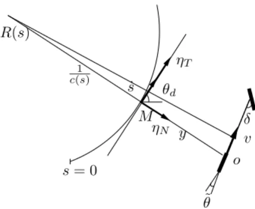
For simplicity the vehicle is simplified with a bicycle model such that the two actual front wheels are equivalent to a unique virtual wheel located at the mid-distance between the actual wheels. The angle between the axis of the front wheels and the vehicle body is called the steering angle δ which is adjusted to allow the vehicle to follow the desired path. The direction of the rear wheels is fixed along the body axis.
In this paper the kinematic model is expressed with
re-spect to the path in frame(M, ηT, ηN), variables necessary
in the kinematic model are denoted as follow: (see figure 1)
• C is the path to be followed.
• O is the center of the vehicle virtual rear wheel. • M is the orthogonal projection of O on path C, M
exits and is uniquely defined if the path meets some conditions.
• ηT is the tangent vector to the path at M .
• ηN is the normal vector at M .
• y is the lateral deviation between O and M
• s is the curvilinear coordinates (arc-length) of point M
along the path from an initial position.
• c(s) is the curvature of the path at point M .
• θdis the orientation of the tangent to the path at point
M .
• θ is the orientation of the vehicle centerline with
respect to the inertia frame.
• θ˜= θ − θd is the orientation error. • l is the vehicle wheelbase. • v is the vehicle linear velocity.
• δ is the steering angle of the virtual front wheel
So the new set of state vectors in the path frame is
(y, s, ˜θ), the path following problem consists of finding a
feedback control law
δ= K(s, y, ˜θ, v) (1) such that lim t→∞y= 0 (2) lim t→∞ ˜ θ= 0 (3) s= 0 θd ˜ θ ˙s v ηT ηN M y δ 1 c(s) o R(s)
Fig. 1. Notation and path frame description
B. Kinematic model
Assuming the vehicle moves without sliding, the ideal
kinematic model of the vehicle with the state (y, s, eθ) is
(see [1]) ˙s = vcos ˜θ 1 − c(s)y ˙y = v sin ˜θ ˙˜θ = v³ tan δ l − c(s) cos ˜θ 1 − c(s)y ´ (4)
But when sliding effects are taken into account, the pure rolling constraint is violated, (4) is no longer valid. To describe the violation of the pure rolling constraint, a vehicle-oriented model is built in which the sliding effects are introduced as additive disturbances which may cause uncertain effects on the vehicle performances, the vehicle-oriented kinematic model is
˙s = vcos ˜θ 1 − c(s)y + ε1 ˙y = v sin ˜θ+ ε2 ˙˜θ = v³ tan δ l − c(s) cos ˜θ 1 − c(s)y ´ + ε3 (5)
where ε is the vector depicting the violation of the ideal rolling without sliding constraints, ε is bounded by a known
constant γ, that is|εi| ≤ γi.
In actual applications, the longitudinal friction is much larger than the sliding force and the longitudinal velocity
varies slowly enough, so in this paper the sliding effect ε1in
the longitudinal direction is negligible, the vehicle-oriented kinematic model is rewritten as
˙s = vcos ˜θ 1 − c(s)y ˙y = v sin ˜θ+ ε2 ˙˜θ = v³ tan δ l − c(s) cos ˜θ 1 − c(s)y ´ + ε3 (6)
III. PREVIOUS WORKS
A. Chained system properties
As presented in [1], in our previous work a path following controller has been designed by converting the model (4)
into a chained system which allows using linear system theories to design nonlinear controllers without any approx-imation while still relying on the actual nonlinear system model (see [7]). For a 3-D nonlinear system with two control inputs, the general chained system is written as
derivation w.r.t t ˙a1= m1 ˙a2= a3m1 ˙a3= m2 (7)
where A= [a1, a2, a3] and M = [m1, m2] are respectively
the states and control inputs of the chained system. The general chained system can be converted into a single-input linear system by replacing the time derivative with
a derivation with respect to the state variable a1. Using the
notation d da1 ai= a ′ i and m3= m2 m1 (8) the general chained system is changed into
derivation w.r.t a1 a′ 1= 1 a′ 2= a3 a′ 3= m3 (9)
where m3 is the virtual control input.
B. Automatic guidance based on chained form system
Considering the kinematic model (4), via state transfor-mation as following
(a1, a2, a3) = (s, y, (1 − c(s)y) tan ˜θ) (10)
the ideal kinematic model is transformed into the general chained system (7) in which
m1= vcos ˜θ 1 − yc(s) m2= d dt((1 − yc(s)) tan ˜θ) = −vc(s) sin ˜θtan ˜θ− vdc(s) ds cos ˜θ
1 − yc(s)tan ˜θy + v1 − yc(s) cos2θ˜ µ tan δ l − c(s) cos ˜θ 1 − yc(s) ¶ (11) Form (10)(11), the expression of the single-input linear system (9) can be obtained. In [1] the virtual control input
m3 is designed to be a PD-type controller
m3= −Kda3− Kpa2 (Kp, Kd) ∈ R+2 (12) which leads to a′′ 2+ Kda ′ 2+ Kpa2= 0 (13)
It is easy to prove that both the state a2 and a3 can
con-verge to zero asymptotically by choosing Kd, Kp. Through
inverse conversion, the physical control law is obtained as
δ(y, ˜θ) = arctan µ l · cos3θ˜ (1 − yc(s))2 ³ dc(s) ds ytan ˜θ −Kd(1 − yc(s)) tan ˜θ− Kpy
+c(s)(1 − yc(s)) tan2θ˜´+c(s) cos ˜θ
1 − yc(s) ¸
(14)
Satisfactory path following results have been reported in [1] provided the vehicles move without sliding.
But in actual applications especially when vehicles move on a slippery ground or make a turn on a slope, the substantial sliding effects cannot be ignored which causes a significant lateral deviation.
IV. ROBUST CONTROL LAW DESIGN
In this section a sliding mode controller is designed based on the vehicle-oriented kinematic model (6) in which sliding effects are considered as additive disturbances.
A. Sliding mode control for perturbed chained system
[9] has designed a sliding mode controller to stabilize a nonholonomic perturbed systems, but all the disturbances have to satisfy a linear constraint. [10] has investigated the problem of designing robust controllers for general chained systems. A sliding mode controller was designed after the chained system was converted into a single-input and varying linear model by setting one input as a time-varying function, but unfortunately the system becomes no longer always controllable. To overcome this problem a new scheme is proposed in this paper to design a sliding mode controller with the help of the natural algebraic structure of chained systems.
Considering the kinematic model (6), a perturbed chained system (15) can be obtained when the same coordinates transformation (10) is used, derivation w.r.t t ˙a1= vcos ˜θ 1 − yc(s) = m1 ˙a2= v sin ˜θ+ ε2= a3m1+ ε2 ˙a3= d dt((1 − yc(s)) tan ˜θ) = m2+ η (15) where η= (1 − yc(s))ε3 cos2θ˜ − c(s)ε2tan˜θ (16)
Noting that in (15) ai and mi have the same expression
as it in (10-11), ε2 and η act as two additive disturbances
to the ideal system (7). So similarly (15) can be converted into a perturbed single-input linear system by computing
the derivative with respect to the state variable a1.
derivation w.r.t a1 a′ 1= 1 a′ 2= a3+ ε2 m1 a′ 3= m2 m1 + η m1 = u + η m1 (17)
where u is the virtual control input of the disturbed single-input system (17). Remarking that u is velocity independent,
ε2
m1 and
η
m1 are bounded. Because the single-input model
(17) contains uncertain bounded disturbances, sliding mode control theories are applied to design a robust controller which may guarantee the system states converge to a neighborhood near the origin.
Concerning the states a2, a3for the path following
prob-lem, the sliding surface is defined as
z= Λa2+ a3 (18)
One condition that guarantees the system states reach the
sliding manifold z = 0 in finite time and remain in this
mode in future time is z˙z < 0. Once the sliding manifold
is encountered, the system stability is achieved with an exponential convergence.
Theorem 2: Define a strictly increasing function
s(t) = Z t
0
v+(τ )dτ (19)
where v+is positive definite and use the notation that(⋄)′
= d⋄
ds, if the sign of v
+(τ ) is kept positive, then the condition
zz′
<0 is equivalent to the reaching condition z ˙z < 0.
Prove: zz′ = zdz ds = z dz dt dt ds= z ˙z 1 v+(τ ) (20) if zz′
<0 then it is easy to prove that the reaching condition z˙z < 0 is satisfied provided v+(τ ) is kept positive. 2
In our applications, s(t) is the curvilinear coordinates of
point M , v+(τ ) is the linear velocity of point M along the
desired path C. v+(τ ) = m1, since the orientation deviation
˜
θ of the vehicle with respect to the desired path C varies
in the range of(−π
2, π
2) and the vehicle remains closed to
the desired path which means that 1 − yc > 0, from (11)
the condition of v+(τ ) > 0 is satisfied.
Theorem 3: Considering the system (15) where
(a1, a2, a3) =¡s, y,(1 − c(s)y) tan ˜θ¢, define
z= Λa2+ a3= Λy + (1 − yc(s)) tan ˜θ (21)
the achievement of sliding motions on the sliding surface (21) can be guaranteed by the control law
u= −kz − Λa3− ρsign(z) (22) where ρ≥ |ς| =¯¯¯Λε2+ η m1 ¯ ¯ ¯ (23)
Prove: For the states a2, a3, consider the reaching
con-dition of sliding mode control:
zz′ = z(Λa′ 2+ a ′ 3) = z³Λa3+ u + Λε2+ η m1 ´ = z³Λa3+ u + ς ´ (24)
Applying (22) into (24), we get
zz′
= z³Λa3− kz − Λa3− ρsign(z) + ς
´
<−kz2− (ρ − |ς|)|z| (25)
if we choose ρ following (23), then the reaching condition
zz′
< 0 is satisfied guaranteeing a sliding motion on the
sliding surface (21). On the sliding surface (21), one has
z= Λa2+ a3= 0 (26) which leads to a′ 2= −Λa2+ ε2 m1 = −Λa2+ ̟ (27)
The stability of system (27) has been analyzed in [11] in
detail, from (27) a2 can be expressed as
a2= e −Λs a2(0) + ̟ Λ = a2(0)e −ΛRt 0v +(τ )dτ +̟ Λ (28)
so the solutions of the resulting closed-loop system are
globally uniformly ultimately bounded. 2
Due to the definition of a2, a3in (10), it is proven that the
lateral deviation y and the orientation error ˜θ are globally
uniformly ultimately bounded in the presence of sliding effects.
Sliding mode control (22) is simple, robust and can guarantee transient performances, but the low level delay caused by hydraulic-driven steering systems always results in chattering responses which may wear down the actuator and excite unmodeled dynamics, possibly compromising performance and even stability. To mitigate the problem of chatter, the signum function is replaced by the hyperbolic
tangent function tanh()
u= −kz − Λa3− ρtanh(
0.2785ρz
σ ) σ >0 (29)
Combining (11) with (29), the physical steering angle is obtained by inverse conversion of the virtual robust control law u. δ(y, ˜θ) = arctan µ l · cos3θ˜ (1 − yc(x))2 ³ dc(s) ds ytan ˜θ + u + c(s)(1 − yc(s)) tan2θ˜´+ c(s) cos ˜θ
1 − yc(s)
¸¶ (30)
Remarking that some constraints have to be added to the system to ensure the validity of the controller:
• Because of the definition of m1in (11) which requires
1 − yc(s) 6= 0, the vehicle is not allowed to pass
the curvature center of the path c, which means that
y < c(s)1 holds and makes the definition of ρ in (23) reasonable.
• Because of the definition of m2in (11) which requires
cos ˜θ 6= 0, the vehicle body axis may not vertical to
the path, the orientation error varies only in the range
of (−π
2, π 2).
However the importance of the constraints is limited due to the small path curvatures and the restricted range of the steering angle in most practical cases.
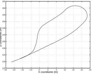
V. SIMULATION RESULTS
In this section, some simulation results are presented to validate the proposed control law. In order to fully demon-strate the effectiveness of the controller, two reference paths consisting of straight lines and curves are followed (see figure 2 and 5), the sliding effects are introduced to the system when the vehicle follows the desired path stepping into a curve. To simulate all the other external unconsidered
disturbances, noises are always added to the system through the same channel as the control inputs. In the simulations,
the gains used in the control law (22) are set as Λ = 0.3
ρ = 0.08, k = 0.3. To compare the control performances
with the previous works, the control laws (14) are applied under the same condition except that we set the controller
gains as kp= 0.09, kd = 0.6.
The simulation results of the lateral deviation for two path-following experiments are shown by figure 3 and 6 respectively, the results of the orientation errors are shown in figure 4 and 7. In the simulation results, the dashed line represents the results yielded by using the controller (14), the solid line depicts the results obtained by applying the sliding mode controller (30) proposed in this paper.
Because the control law (14) does not take sliding effects into account and from theoretical point of view, the PD-type virtual control law is not robust against disturbances, it is clear that it suffers from sliding greatly, when the sliding effects appear, its lateral deviation becomes more significant than the other. While the sliding mode control law proposed in this paper provides satisfactory simulation results, it has good transient responses and is robust against not only the sliding effects but also other input noises which inevitably occur in actual applications, the simulation results show that the sliding effects affect both the lateral deviation and the orientation error weakly.
VI. CONCLUSION
The path following problem of autonomous agricultural vehicles in the presence of sliding is investigated in this paper. A vehicle-oriented kinematic model which integrates the sliding effects as additive disturbances is used. From this model, a particular perturbed chained system is evolved. The use of the attractive structure of chained systems together with the sliding mode control leads to a robust controller which is robust to both the sliding effects and external disturbances. The system states have been theoret-ically proved globally uniformly ultimately bounded. The advantage of this new scheme is that
• The anti-sliding controller proposed in this paper is
developed still relying on chained system properties, so abundant linear system theories are available to design more powerful controllers without loss of nonlinear features.
• This scheme is a primary work of designing robust
controllers for chained systems. Since chained systems have a perfect natural structure for the use of sliding mode control, some skillful high-dimensional sliding surfaces can be designed to fulfill more complicated tasks, for example longitudinal control or anti-sliding control of vehicles with four-wheel steering kinematic model.
• This scheme does not require more sensors and costs
less on-board computation which yields a easy actual implementation. −220 −210 −200 −190 −180 −170 −160 100 110 120 130 140 150 160 X coordiante (m) y coordiante (m)
Fig. 2. Path to be followed
0 50 100 150 200 250 300 350 400 450 500 −0.2 −0.1 0 0.1 0.2 0.3 0.4 0.5 0.6 Time (s) Lateral Deviation (m) Sliding Period
Fig. 3. Lateral deviation
0 50 100 150 200 250 300 350 400 450 500 −15 −10 −5 0 5 10 15 Time (s)
Orientation Error (Degree)
−25 −20 −15 −10 −5 0 5 10 15 20 25 115 120 125 130 135 140 145 150 155 160 165 X coordiante (m) y coordiante (m)
Fig. 5. Path to be followed
0 100 200 300 400 500 600 −5 −4 −3 −2 −1 0 1 Time (s) Lateral Deviation (m) Sliding Period
Fig. 6. Lateral deviation
0 100 200 300 400 500 600 −80 −60 −40 −20 0 20 40 Time (s)
Orientation Error (Degree)
Fig. 7. Orientation error
Experimental comparative results with previous schemes show the effectiveness of the proposed control law.
REFERENCES
[1] Thuilot B, Cariou C, Martinet P, and Berducat M, “Automatic guid-ance of a farm tractor relying on a single CP-DGPS”, Autonomous robots , 13(1): 87-104,2002
[2] I.Motte, H. Campion, “Control of sliding mobile robots : a slow manifold approach”, MNTS 2000
[3] W. Leroquais, B. D’Andera-Novel, “ Vibrational control of wheeled mobile robots not satisfying ideal evlocity constraints: the unicycle case ”, European Control Conference, July 1-4, Brussels,1997 [4] Y.L.Zhang, J.H.Chung, S.A.Velinsky, “ Variable structrue control of
a differentially steered wheeled mobile robot”, Jounal of intellignet and Robotic Systems, 36:301-314,2003
[5] M.L.Corradini and G. Orlando, “Experimental testing of a discrete-time sliding mode controller for trajectory tracking of a wheeled mobile robot in the presence of skidding effects”, Journal of robotic systems, 19(4), 177-188, 2002
[6] B. D’Andera-Novel, G.Campion, and G.Bastin. “Control of wheeled mobile robots not satisfying ideal constraints: a singular perturbation approach”. Internaltinal Journal of Robust Nonlinear Control, 5:243-267,1995.
[7] Samson,C Control of chianed systems, “Applicatoin to path following and time-varying point stabilization of mobile robot”, IEEE Trans,on Automatic Control, 39(12):2411-2425,1995
[8] Lenain R. Thuilot B. Cariou C, Martinet P. “Adaptive control for car like vehicles guidance relying on RTK GPS: rejection of sliding effects in agricultural applications”, In Proc. of the intern. Conf. On Robotics and Automation, Taibei, Sept, 2003.
[9] T.Floquet, J-P.Barbot, W.Perruquetti, “One-chained form and sliding mode stabilization for nonholonomic perturbed systems”, Proceed-ing of the American Control Conference, Chicago,Illinois,:3264-3268,June 2000
[10] J.Lu, S.Sekhavat, M. Xie,and C.Laugier, “Sliding mode control for nonholonomic mobile robot”, In Proc. of the Int. Conf. on Control, Automation, Robotics and Vision, Singapore, December 2000. [11] ZP. Jiang, David J.Hill, “A robust adaptive backstepping scheme
for nonlinear systems with unmodeled dynamics”,IEEE Trans. Auto Contr., vol.44, pp. 1705-1711,1999