https://doi.org/10.4224/20374409
READ THESE TERMS AND CONDITIONS CAREFULLY BEFORE USING THIS WEBSITE.
https://nrc-publications.canada.ca/eng/copyright
Vous avez des questions? Nous pouvons vous aider. Pour communiquer directement avec un auteur, consultez la
première page de la revue dans laquelle son article a été publié afin de trouver ses coordonnées. Si vous n’arrivez pas à les repérer, communiquez avec nous à [email protected].
Questions? Contact the NRC Publications Archive team at
[email protected]. If you wish to email the authors directly, please see the first page of the publication for their contact information.
NRC Publications Archive
Archives des publications du CNRC
For the publisher’s version, please access the DOI link below./ Pour consulter la version de l’éditeur, utilisez le lien DOI ci-dessous.
Access and use of this website and the material on it are subject to the Terms and Conditions set forth at
Characterization of low temperature creep properties of crack sealants
using bending beam rehometry
Al-Qadi, I. L.; Yang, S.-H.; Elsefi, M. A.; Dessouky, S.; Loulizi, A.; Masson,
J.-F.; McGhee, K. K.
https://publications-cnrc.canada.ca/fra/droits
L’accès à ce site Web et l’utilisation de son contenu sont assujettis aux conditions présentées dans le site LISEZ CES CONDITIONS ATTENTIVEMENT AVANT D’UTILISER CE SITE WEB.
NRC Publications Record / Notice d'Archives des publications de CNRC:
https://nrc-publications.canada.ca/eng/view/object/?id=8e51ba47-3728-4e42-ae7f-ebeba6411115 https://publications-cnrc.canada.ca/fra/voir/objet/?id=8e51ba47-3728-4e42-ae7f-ebeba6411115
http://www.nrc-cnrc.gc.ca/irc
Cha ra c t e riza t ion of low t e m pe ra t ure c re e p prope rt ie s of c ra c k
se a la nt s using be nding be a m re hom e t ry
N R C C - 5 3 2 5 4
Al-Qadi, I.L.; Yang, S.-H.; Elsefi, M.A.; Dessouky, S.; Loulizi, A.; Masson,
J.-F.; McGhee, K.K.
M a r c h 2 0 1 0
A version of this document is published in / Une version de ce document se trouve dans:
Illinois Center for Transportation, pp. 52, November 01, 2008
The material in this document is covered by the provisions of the Copyright Act, by Canadian laws, policies, regulations and international agreements. Such provisions serve to identify the information source and, in specific instances, to prohibit reproduction of materials without
written permission. For more information visit http://laws.justice.gc.ca/en/showtdm/cs/C-42
Les renseignements dans ce document sont protégés par la Loi sur le droit d'auteur, par les lois, les politiques et les règlements du Canada et des accords internationaux. Ces dispositions permettent d'identifier la source de l'information et, dans certains cas, d'interdire la copie de
CHARACTERIZATION OF LOW TEMPERATURE
CREEP PROPERTIES OF CRACK SEALANTS
USING BENDING BEAM REHOMETRY
Prepared By
Imad L. Al-Qadi
Shih-Hsien Yang
University of Illinois at Urbana-Champaign
Mostafa A. Elseifi
Louisiana State University
Samer Dessouky
University of Texas at San Antonio
Amara Loulizi
Re'seau National Universitaire, Tunisia
Jean-François Masson
National Research Council of Canada
Kevin K. McGhee
Virginia Transportation Research Council
Research Report ICT-08-029
Illinois Center for Transportation
November 2008
CIVIL ENGINEERING STUDIES
Illinois Center for Transportation Series No. 08-029 UILU-ENG-2008-2017
Technical Report Documentation Page
1. Report No.
FHWA-ICT-08-029
2. Government Accession No. 3. Recipient's Catalog No.
4. Title and Subtitle
CHARACTERIZATION OF LOW TEMPERATURE CREEP PROPERTIES OF CRACK SEALANTS USING BENDING BEAM REHOMETRY
5. Report Date
November 2008
6. Performing Organization Code
8. Performing Organization Report N o. 7. Author(s)
Imad L. Al-Qadi, Shih-Hsien Yang, Mostafa A. Elseifi, Samer Dessouky, Amara Loulizi, Jean-François Masson, Kevin K. McGhee
ICT-08-029
UILU-ENG-2008-2017
9. Performing Organization Name and Address
University of Illinois at Urbana Champaign
Department of Civil and Environmental Engineering 205 N. Mathews Ave, MC-250
Urbana, Illinois 61081
10. Work Unit ( TRAIS)
11. Contract or Grant No.
VTRC Project # 67775 TPF-5(045)
13. Type of Report and Period Covered
Technical Report
12. Sponsoring Agency Name and Address
Federal Highway Administration 400 North 8th Street, Room 750 Richmond, VA 23219-4825
Virginia DOT – Lead State 1401 E. Broad St
Richmond, VA 23219
14. Sponsoring Agency Code
15. Supplementary Notes
16. Abstract
Crack sealing has been widely used as a routine preventative maintenance practice. Given its proper installation, crack sealants can extend pavement service life by three to five years. However, current specifications for the selection of crack sealants correlate poorly with field performance. The purpose of this research was to develop performance guidelines for the selection of hot-poured bituminous crack sealants at low temperature. In this part of the research, the creep behavior of crack sealant at low temperature is measured and performance criteria for material selection were developed. Because various pavement and State agencies are well acquainted with and own the Bending Beam Rheometer (BBR), which was developed during the Strategic Highway Research Program (SHRP), an attempt was made to utilize the same setup to test hot-poured bituminous-based crack sealants. Testing conducted in this research project indicated that the standard BBR was inappropriate for testing soft bituminous-based hot-poured crack sealant, even at -40°C. The measured deflection exceeded the BBR limit, for some sealants, after only a few seconds of loading. To address this issue, the moment of inertia of the tested beam was increased by doubling its thickness (from 6.35mm to 12.7mm). For the new beam dimensions, it was found that only 4% of the beam center deflection is due to shear, a value deemed acceptable for sealant evaluation and comparison.
In an effort towards developing a robust testing procedure, 15 sealants from various manufacturers were included in the study and tested between –4°C and –40°C. In addition, five sealants, which have known field performance, were tested to validate the laboratory results and establish specification thresholds for the selection guidelines. Since stiffness calculation in the BBR test method requires that measurements be made within the linear region of viscoelastic behavior, validation of this theory was conducted for crack sealants. This was found to be generally the case with crack sealants, which allowed for the use of the time-temperature superposition. If the temperature-superposition principle is applied, the stiffness at 240s at a given temperature can be used to predict the stiffness after 5hr of loading at a temperature that is 6°C lower. With the assumption of linear viscoelastic behavior, sealants performance can be characterized through stiffness, average creep rate, and dissipated energy ratio. Stiffness was found to be sensitive to temperature changes and could be used to differentiate between sealants. The measurements of the average creep rate and the dissipated energy ratio were also found to be valuable in differentiating between sealants. In addition, numerical modeling was used to simulate the mechanical response of crack sealants at low temperatures. Parameters that may be used for evaluating crack sealant cohesive performance using the crack sealant BBR (CSBBR) are the stiffness at 240s, average creep rate, and the dissipated energy ratio. For simplicity, the first two parameters, stiffness at 240s and average creep rate, are recommended for
implementation in the sealant performance grade. The recommended thresholds are maximumstiffness of 25MPa and minimum average creep rate of 0.31.
17. Key Words 18. Distribution Statement
No restrictions. This document is available to the public through the National Technical Information Service, Springfield, Virginia 22161.
ACKNOWLEDGEMENT
The research on the Development of Performance-Based Guidelines for the
Selection of Bituminous–Based Hot-Poured Pavement Crack Sealants is sponsored by the Federal Highway Administration “pooled-fund study TPF5 (045)” and the US-Canadian Crack Sealant Consortium. The contribution of the participating states, industry, and provinces is acknowledged. This report is part of a series of reports that resulted from this study. Four reports were published by the Illinois Center for Transportation:
Al-Qadi, I.L., E.H. Fini, H.D. Figueroa, J.-F Masson, and K.K. McGhee, Adhesion Testing Procedure for Hot-Poured Crack Sealants, Final Report, No. ICT-08-026, Illinois Center for Transportation, Rantoul, IL, Dec 2008, 103 p.
Al-Qadi, I.L., E.H. Fini, J.-F Masson, A. Loulizi, K.K. McGhee, M.A. Elseifi,
Development of Apparent Viscosity Test for Hot-Poured Crack Sealants, Final Report, No. ICT-08-027, Illinois Center for Transportation, Rantoul, IL, Dec 2008, 41 p.
Al-Qadi, I.L., S.-H. Yang, J.-F. Masson, and K.K. McGhee, Characterization of Low Temperature Mechanical Properties of Crack Sealants Utilizing Direct Tension Test, Final Report, No. ICT-08-028, Illinois Center for Transportation, Rantoul, IL, Dec 2008, 70 p.
Al-Qadi, I.L., S.-H. Yang, M.A. Elseifi, S. Dessouky, A. Loulizi, J.-F. Masson, and K.K. McGhee, Characterization of Low Temperature Creep Properties of Crack Sealants Using Bending Beam Rheometry, Final Report, No. ICT-08-029, Illinois Center for Transportation, Rantoul, IL, Dec 2008, 81 p.
Two internal reports on aging and sealant characterization were published by the National Research Council of Canada and a summary can be found in the following papers):
Collins, P., Veitch, M., Masson, J-F., Al-Qadi, I. L., Deformation and Tracking of Bituminous Sealants in Summer Temperatures: Pseudo-field Behaviour,
International Journal of Pavement Engineering, Vol. 9, No. 1, 2008, pp. 1-8.
Masson, J-F., Woods, J. R., Collins, P., Al-Qadi, I. L., Accelerated Aging of Bituminous Sealants: Small-kettle Aging, International Journal of Pavement
Engineering, Vol. 9, No. 5, 2008, pp. 365-371.
In addition, an executive summary report of the study was published by the Virginia Transportation Research Council (the leading state of the study):
Al-Qadi, I. L. J-F. Masson, S-H. Yang, E. Fini, and K. K. McGhee, Development of Performance-Based Guidelines for Selection of Bituminous-Based Hot-Poured Pavement Crack Sealant: An Executive Summary Report, Final Report, No. VTRC 09-CR7, Virginia Department of Transportation, Charlottesville, VA, 2008, 40 p.
DISCLAIMER
The project that is the subject of this report was completed under contract with the Virginia Transportation Research Council, which served as lead-state coordinator and project monitor for the partner states of Connecticut, Georgia, Maine, Michigan, Minnesota, New Hampshire, New York, Rhode Island, Texas, and Virginia. The contents of this report reflect the views of the authors, who are responsible for the facts and the accuracy of the data presented herein. The contents do not necessarily reflect the official views or policies of the Virginia Transportation Research Council, the partnering states, the Illinois Center for Transportation, the Illinois Department of Transportation, the Federal Highway
Administration, or the remaining members of the Crack Sealant Consortium. This report does not constitute a standard, specification, or regulation. Any inclusion of manufacturer names, trade names, or trademarks is for identification purposes only and is not to be considered an endorsement.
EXECUTIVE SUMMARY
Crack sealing has been widely used as a routine preventative maintenance practice. Given its proper installation, crack sealants can extend pavement service life by three to five years. However, current specifications for the selection of crack sealants correlate poorly with field performance. The purpose of this research was to develop performance
guidelines for the selection of hot-poured bituminous crack sealants at low temperature. In this part of the research, the creep behavior of crack sealant at low temperature is
measured and performance criteria for material selection were developed. Because various pavement and State agencies are well acquainted with and own the Bending Beam
Rheometer (BBR), which was developed during the Strategic Highway Research Program (SHRP), an attempt was made to utilize the same setup to test hot-poured bituminous-based crack sealants. Testing conducted in this research project indicated that the standard BBR was inappropriate for testing soft bituminousbased hotpoured crack sealant, even at -40°C. The measured deflection exceeded the BBR limit, for some sealants, after only a few seconds of loading. To address this issue, the moment of inertia of the tested beam was increased by doubling its thickness (from 6.35mm to 12.7mm). For the new beam
dimensions, it was found that only 4% of the beam center deflection is due to shear, a value deemed acceptable for sealant evaluation and comparison.
In an effort towards developing a robust testing procedure, 15 sealants from various manufacturers were included in the study and tested between –4°C and –40°C. In addition, five sealants, which have known field performance, were tested to validate the laboratory results and establish specification thresholds for the selection guidelines. Since stiffness calculation in the BBR test method requires that measurements be made within the linear region of viscoelastic behavior, validation of this theory was conducted for crack sealants. This was found to be generally the case with crack sealants, which allowed for the use of the time-temperature superposition. If the temperature-superposition principle is applied, the stiffness at 240s at a given temperature can be used to predict the stiffness after 5hr of loading at a temperature that is 6°C lower.
With the assumption of linear viscoelastic behavior, sealants performance can be characterized through stiffness, average creep rate, and dissipated energy ratio. Stiffness was found to be sensitive to temperature changes and could be used to differentiate
between sealants. The measurements of the average creep rate and the dissipated energy ratio were also found to be valuable in differentiating between sealants. In addition,
numerical modeling was used to simulate the mechanical response of crack sealants at low temperatures. Parameters that may be used for evaluating crack sealant cohesive
performance using the crack sealant BBR (CSBBR) are the stiffness at 240s, average creep rate, and the dissipated energy ratio. For simplicity, the first two parameters, stiffness at 240s and average creep rate, are recommended for implementation in the sealant
performance grade. The recommended thresholds are maximum stiffness of 25MPa and minimum average creep rate of 0.31.
TABLE OF CONTENTS
ACKNOWLEDGEMENT ... I DISCLAIMER ... II EXECUTIVE SUMMARY ... III TABLE OF CONTENTS ... IV
INTRODUCTION ... 1
PURPOSE AND SCOPE ... 2
METHODS ... 3
CRACK SEALANT BENDING BEAM RHEOMETER (CSBBR) ... 3
SuperPaveTM Bending Beam Rheometer ... 4
Bending Beam Rheometer Equipment Evaluation and Test Modification ... 5
TIME-TEMPERATURE SUPERPOSITION PRINCIPLE VERIFICATION AT LOW TEMPERATURE ... 6
EFFECT OF AGING ... 6
BITUMINOUS-BASED CRACK SEALANT TYPES AND IDENTIFICATIONS ... 7
COHESIVE PERFORMANCE AT LOW TEMPERATURE –LABORATORY PARAMETERS ... 9
Crack Sealant Stiffness ... 9
Average Creep Rate ... 11
Dissipated Energy Ratio ... 12
VISCOELASTIC BEHAVIOR AND MODELING ... 13
Mechanical Response of Hot-Poured Bituminous-Based Crack Sealant ... 14
Kelvin-Voigt Viscoelastic Model ... 15
Three-Dimensional Finite Element Model ... 18
Experimental Design ... 20
RESULTS AND DISCUSSION ... 21
CRACK SEALANT BENDING BEAM RHEOMETER (CSBBR) ... 21
BBR Equipment Evaluation ... 21
Modifications to the Asphalt Binder Test Procedure ... 23
Test Repeatability ... 25
TIME-TEMPERATURE SUPERPOSITION PRINCIPLE VERIFICATION AT LOW TEMPERATURE ... 30
EFFECT OF AGING ... 31
COHESIVE PERFORMANCE AT LOW TEMPERATURE –LABORATORY PARAMETERS ... 32
Crack Sealants Stiffness (S) ... 32
Average Creep Rate ... 32
Dissipated Energy Ratio ... 32
VISCOELASTIC BEHAVIOR AND MODELING ... 34
Data Reduction and Analysis ... 34
Model Validation ... 38 TEST VARIATION ... 41 FIELD VALIDATION ... 43 Sealant A ... 45 Sealant B ... 45 Sealant E ... 45 Sealant G ... 46 Sealant J ... 46
SUMMARY AND CONCLUSIONS ... 47
RECOMMENDATIONS ... 48
ACKNOWLEDGMENTS ... 48
REFERENCES ... 49 APPENDIX A: CSBBR TESTING PROCEDURE ... A-1 APPENDIX B: SPECIMEN SIZE EFFECT OF BENDING BEAM RHEOMETER ... B-1 APPENDIX C: TEST SPECIFICATION ... C-1
FINAL CONTRACT REPORT
CHARACTERIZATION OF LOW TEMPERATURE MECHANICAL PROPERTIES OF CRACK SEALANTS USING BENDING BEAM RHEOMETRY
Imad L. Al-Qadi
Founder Professor of Engineering Illinois Center for Transportation, Director Department of Civil and Environmental Engineering
University of Illinois at Urbana-Champaign
INTRODUCTION
Crack sealing and filling are the most widely used maintenance activity for in-service pavements. This preventive maintenance activity is particularly favored among pavement agencies because it is inexpensive, quick, and well-proven to delay the pavement
deterioration caused by other mechanisms, such as weakening of subgrade and aggregate layers through water infiltration and stripping of hot-mix asphalt (HMA) layers. Several years of service life may be added to a pavement at a relatively low cost if an appropriate sealant material is correctly installed at the right time. Several studies demonstrated the cost-effectiveness of crack sealing and filling (Joseph 1990; Cuelho et al. 2002; Cuelho et al. 2003; Fang et al. 2003; Ward 2001; Chong and Phang 1987; Chong 1990). Chong and Phang (1987) reported that crack sealing added about four years of life to flexible
pavements. Chong (1990) also reported that maximum cost-effectiveness was achieved when the first treatment was performed between the third and fifth year of the pavement service life and a second treatment between the eighth and ninth year of the pavement service life.
In order to maintain a cost-effective crack sealing/filling operation and achieve the expected performance of crack sealnts, two factors must be closely controlled: quality of the installation and sealant mechanical and rheological properties (such as viscosity, bulk stiffness, and adhesive bond strength). Regardless of sealant quality, improper installation will cause premature failure and lead to a shorter service life. The installed sealant material should also have the appropriate rheological properties to adequately accommodate crack movements, particularly during the winter season. Cracks in pavements may move in both horizontal and vertical directions. Vertical movement is a result primarily of traffic loading. Because the crack may divide the pavement into two parts, differential movement between the two parts occurs when the load transfer is not full; this is usually referred to as a
“working crack”. Horizontal movement in a crack is primarily due to thermal expansion and contraction of the pavement. Thermally-induced movements tend to occur on a seasonal basis rather than on a daily basis (Linde 1988). Cracks open the most during winter, and tend to close during summer, and they rarely return to their original width. In fact, cracks seem to increase in width every year. In some cases, cracks were found to move a considerable amount, while in other cases; they barely moved (Linde 1988).
Existing standards and specifications in the United States and Canada describe specific test methods to measure the properties of crack sealants. Laboratory tests and specifications for crack sealant materials were established by several organizations,
including American Society for Testing and Materials (ASTM), American Association of State Highway and Transportation Officials (AASHTO), and U.S. and Canadian federal, state, provincial, and municipal agencies. Chehovits and Manning (1984) reported that eight specific properties are desirable in a product to perform adequately as a crack sealant: 1. ability to be easily and properly placed in a crack with application equipment, 2. adequate adhesion to remain bonded to HMA crack faces,
3. adequate resistance to softening and flow at high, in-service pavement temperatures so that the sealant will not flow from the crack,
4. adequate flexibility and extensibility to remain bonded to crack faces when extended at low, in-service temperatures,
5. sufficient elasticity to restrict the entrance of incompressible materials into the crack, 6. sufficient pot life at application temperatures,
7. resistance to degradation from weather to ensure long in-service life of the sealant, and 8. compatibility with HMA, and low cure time to allow traffic as soon as possible after
application.
Several empirical tests exist that are thought to indicate whether a selected crack sealant material possesses the required properties. ASTM Standard D5329-04 (Standard Test Methods for Sealants and Fillers, Hot-Applied, for Joints and Cracks in Asphaltic and Portland Cement Concrete Pavements) summarizes most of these tests. These include immersed cone penetration, fuel-immersed cone penetration, the flow test, the non-immersed bond test, the water-non-immersed bond test, the fuel-non-immersed bond test, the resilience test, the oven-aged resilience test, the asphalt compatibility test, the artificial weathering test, the tensile adhesion test, the solubility test, and the flexibility test.
These tests are used by most state highway agencies in selecting their crack sealing materials; but the specification limits may vary from one state to another. These differences create difficulties for crack sealant suppliers because many states with the same
environmental conditions specify different limits for the measured properties. These tests were also reported to poorly characterize the rheological properties of bituminous-based crack sealants and to predict sealant performance in the field. This may lead to premature sealant failure when used in unfavorable conditions.
The inability of current ASTM and AASHTO standard tests to provide a good indication of field performance has been repeatedly documented in the literature (Belangie and Anderson 1985; Smith and Romine 1999; Masson et al. 1999; Masson 2000). The main reason that current specifications poorly predict field performance is that these tests are empirical and that the measured parameters are not based on any rheological properties. Therefore, it has been a common practice to evaluate the performance of sealing materials through field trials. However, even the results from field tests are sometimes controversial because a sealant can perform well at one site and fail in another, simply because of
differences in environmental or installation conditions. Masson and Lacasse (1999) showed that current ASTM specifications for selecting hot-poured crack sealants are based on tests whose results are not correlated with field performance.
PURPOSE AND SCOPE
The main objective of this project was to develop laboratory tests that measure bituminous-based crack sealants rheological properties, which may improve the selection of sealant materials. Ultimately, the aim was to predict crack sealant performance at a
particular site, with a benefit of being able to select durable sealants. Special attention was given to make use of the equipment originally developed during the five-year Strategic Highway Research Program (SHRP), which were used to measure binder rheological behavior as part of the performance grade (PG) system. At low temperatures, the SHRP BBR was modified and used to predict the cohesive performance of crack sealants. This report describes the research tasks conducted to achieve the objectives of this phase of the study. This included the following research tasks:
• Development of modifications to the binder BBR test setup and specimen preparation originally developed by SHRP.
• Validation of the time-temperature superposition principle for crack sealants and verification of the applicability of the linear viscoelastic theory for these materials at low temperature.
• Evaluate the effect aging process on crack sealants rheological behavior. • Identification of laboratory-measured parameters to predict the cohesive field
performance of crack sealants at low temperature and recommend related thresholds.
METHODS
The key to improving sealant durability is to develop effective performance guidelines for selection and application of sealants. Acknowledging the deficiencies of the current specification system, more than 26 State and Province departments of transportation, manufactures, cities, and research agencies in North America have partnered to develop performance-based guidelines for the selection of bituminous-based hot-poured crack sealants. A major milestone of this project was to make use of the well-established methods and equipment originally developed during the five-year Strategic Highway Research
Program (SHRP) as part of the Performance Grade (PG) system for asphalt binders. Because the equipment utilized in this system is already owned by various pavement and State agencies, this was an attractive and economical choice that was adopted by this research project.
Previous researchers have attempted to test crack sealant using the SHRP bending beam rheometer (BBR); but because of the high flexibility of crack sealants and the large deformation experienced under loading, it was concluded that this equipment was not suitable for measuring the stiffness of these materials (Zanzotto 1996). Therefore, in order to use the equipment developed by SHRP, some modifications were needed to allow for testing hot-poured sealants. The proposed modifications were validated and recommended performance parameters, to characterize creep behavior of hot-poured bituminous-based crack sealants at low temperature using the CSBBR, were suggested.
Crack Sealant Bending Beam Rheometer (CSBBR)
This section presents the results of laboratory tests used to evaluate the application of the SuperPaveTM BBR for testing of crack sealants. This ultimately led to a series of modifications to address the rheological differences between asphalt binder and crack sealant. The modified equipment is referred to as the Crack Sealant Bending Beam Rheometer (CSBBR).
SuperPaveTM Bending Beam Rheometer
Research conducted in the late 1960s and early 1970s suggested that binder stiffness and thermal cracking in flexible pavements are closely correlated, after a loading time ranging from 3,600 to 20,000s (Hills and Brien 1966; Readshaw 1972). Based on this correlation, researchers suggested limiting the creep stiffness at 200MPa after a loading time of 2hr. Based on these field observations, the SuperPaveTM BBR testing protocol imposed upper limit on the measured creep stiffness. However, for practical reasons and assuming the time-temperature superposition principle is valid, loading time in the BBR was reduced from 2hr to 60s while raising the temperature by 10°C. In addition, the maximum allowable creep stiffness was changed from 200 to 300MPa as the original threshold was judged overly restrictive (Anderson et al. 1994). After several preliminary tests, the total loading time of 240s was selected. This loading time provided a sufficient time span to create an overlap between the different creep curves when it is beneficial to construct
master curves spreading over several orders of time magnitude (Bahia and Anderson 1995). In addition to the creep stiffness, the stress relaxation ability of the asphalt binder was also considered and measured from the creep rate, also known as the value. The m-value is the slope of the log stiffness versus log time curve at any time, t. Physically, a higher creep rate (m-value) would indicate a faster relaxation of stresses, which is desirable at low temperature. By applying a constant load to the asphalt beam and measuring the center deflection of the beam throughout a timed test procedure, the creep stiffness (S) and creep rate (m) can be calculated. The creep load simulates the thermal stresses that gradually build up in a pavement when the temperature drops. Based on elementary beam theory, the deflection of a prismatic beam in a three-point bending mode can be calculated using the following equation:
EI 48 PL3 = δ (1) where,
P = constant applied load (N); L = span length (102mm);
δ = deflection of the beam at midspan (mm); E = modulus of elasticity (N/mm2);
I = moment of inertia (mm4) = bh3/12. b = beam width (12.7mm); and h = beam thickness (6.35mm).
The selected beam dimensions (b, h) meet the requirements for applying the
elementary beam theory by keeping the shear effects on the center deflection minimal (less than 1%). For this beam configuration, the span to depth ratio was 16/1, and the depth to width ratio was ½. A major simplification, which was introduced to calculate creep stiffness, assumed that asphalt binder behaves as a linear viscoelastic material. This assumption was evaluated and validated by Marasteanu and Anderson (2000). Using the elastic-viscoelastic correspondence principle, the creep stiffness was then calculated as follows:
) t ( bh 4 PL ) t ( S 3 3 δ = (2) where, S(t) = time-dependent stiffness.
As shown in the previous section, several critical assumptions were made in the analysis of the data obtained from the BBR. Before adopting this equipment for testing bituminous hot-poured sealants for cracks and joints, it is essential to ensure that these assumptions are applicable for crack sealants. Obviously, although there is similarity between asphalt binder and hot-poured crack sealants, some differences exist between the two materials. In fact, hot-poured crack sealants behave similarly to highly modified asphalt rubber.
The first assumption in the SuperPaveTM specification system is that all the
measurements are made in the linear region of viscoelastic behavior. If the measurements are not taken at relatively narrow strain amplitudes, this assumption will not be valid. A departure from the linear region of behavior would necessitate a highly complex analysis to calculate the stiffness of the material, and would mean that the suggested analysis would bear no resemblance to the existing SuperPaveTM binder specification system other than using similar equipment. Therefore, measurements need to be checked for being obtained in the linear region of viscoelastic behavior. The check of linearity suggested by
Marasteanu and Anderson (2000) was adopted in this study.
Another critical assumption made in the SuperPaveTM specification system is that the stiffness after two hours of loading can be approximated by the stiffness after 60s of loading by raising the temperature by 10°C. It was recently reported that this assumption was never validated experimentally in the SHRP program by actually conducting the 2-h tests.
Moreover, recent evaluation of this assumption by Basu and his colleagues indicated that this hypothesis was not correct (Basu et al. 2003). Results of this study indicated that the 60s stiffness values were significantly higher than the 2-h stiffness values and that the differences in stiffness ranged from 32 to 66% depending on the binder type.
A third assumption made in the SuperPaveTM specification system was that the selected conditioning time of one hour is sufficient to reduce the effect of physical hardening on the measured stiffness. During the SHRP program, it was noticed that asphalt binders exhibited a significant hardening that resulted in a sharp increase in the material’s stiffness. This phenomenon increased sharply in the first 24h, and then stabilized to become
negligible after 3 to 7 days. Although the SHRP program did not thoroughly quantify this factor, a standard conditioning time of one hour was decided so that hardening could be discounted. Such selection would need to be validated for crack sealant materials.
The final assumption made in the SuperPaveTM specification system was that the creep stiffness and the slope of changing stiffness (m-value) would suffice to distinguish and grade the low temperature performance of different binders. This is a critical assumption that was investigated by various researchers (Anderson et al. 1994; Hesp, 2004). Based on the results of these studies, it was concluded that the original specification did not accurately reflect the low temperature performance of binders.
Bending Beam Rheometer Equipment Evaluation and Test Modification
While attempt to use SuperPaveTM BBR to test crack sealants, several problems have encountered. The first problem was that the AASHTO TP1-97 binder sample
preparation procedure was followed to evaluate the potential use of this practice for bituminous hot-poured crack sealants. However, although this AASHTO procedure recommends using Mylar strips to prevent the binder adhering to the mold, the technique was not effective with crack sealant materials, as they tended to stick to the mold during de-molding. Several release agents (e.g., a mix of glycerin and talc) were tried, with silicone grease found to work best with crack sealant materials. The second problem encountered during the testing was the relatively soft crack sealant material. Due to the excessive softness of the crack sealant, several tested sealants were too soft to measured by the SuperPaveTM BBR. The specimen quickly deformed within the 240s testing period. To overcome this issue, the specimen thickness was doubled. The third problem was the relatively high variation in testing results. Crack sealant has much more complex
composition compared to asphalt binder. Crack sealant may have high content of polymer, crumb rubber particales, lime, and/or filler. This makes sealant more viscos material compared to asphalt binder and its inhomogeneity becomes a major issue during the sealant pouring into the mold. To overcome this problem, each specimen was poured from individual container, which contains the same amount of sealant sample. This improves the test repeatability significantly.
Time-Temperature Superposition Principle Verification at Low Temperature
The SuperPaveTM specifications for asphalt binder assume that creep responses are measured in the linear region of its viscoelastic behavior. In order for the time-temperature superposition principle to be valid, measurements must be taken at relatively narrow strain amplitudes. Therefore, it is essential to ensure that crack sealants measurements are obtained in the linear region of viscoelastic behavior. Al-Qadi et al. (2006) and Elseifi et al. (2006) have studied quantifying the linear response of sealant materials. The studies utilized two conditions to verify the linearity as suggested by Marasteanu and Anderson (2000). Marasteanu and Anderson (2000) showed that for a linear viscoelastic material, time response measurements should be independent of the applied stress level, and second, the linear superposition principle should be applicable to a sequence of loading and
unloading cycles. Therefore, creep loading at 250, 490, and 980mN was conducted on sealant.
Effect of Aging
When sealant is subjected to weathering, the stiffness of the sealant varies
depending on the chemical composition of the material. Hence, it is important to simulate the effects of aging on sealants because their mechanical properties can be altered from their original state. Sealant aging is typically divided into two categories: short-term aging, which occurs during the installation process, and long-term aging, which occurs after construction, primarily due to climate exposure and loading.
Currently, there is no method to simulate hot-poured bituminous crack sealant aging. Aging effects are usually accounted for by subjecting sealant to simulated aging then
measuring its mechanical properties by conducting standard physical tests (such as
viscosity, dynamic shear rheometer test, BBR test, and the direct tension test). In this study, vacuum oven aging (VOA) was used to simulate the aging and weathering of crack sealants during installation and service.
In this procedure, developed by Masson et al. (2007) as part of this project, the homogenized sealant is cut into slices and then placed in a stainless steel pan in a heated oven in order to achieve a film thickness of less than 2mm. The sealant is then removed from the oven and allowed to cool down at room temperature before enduring accelerated aging in the VOA, which is preheated to 115ºC. The sealant is then transferred into the vacuum oven for 16hr under a vacuum of 760mm of mercury. After this period, the steel pan is placed back into a regular oven at 180°C and heated until the sealant is sufficiently fluid. The sealant from each pan is poured into individual containers, which ensures the homogeneity of the sealant for future performance testing. Through chemical analysis, this procedure was shown to be suitable for aging of bituminous crack sealants. It does not cause significant degradation of polymer constituents nor excessive oxidation.
The aging process was first conducted with Precision vacuum oven model 29 (Figure 1a a). However, a study was conducted to measure the internal temperature distribution in the vacuum oven and showed that the temperature distribution within the oven can be as high as 25°C between the upper and lower shelves. Therefore, a new vacuum oven from Sheldon lab model 1445 (Figure 1b) was used and the measurement showed that a relatively uniform temperature distribution can be achieved when a special design shelves were used in this oven. The special shelves had a height of 23mm and therefore uniform temperature distribution can be reached at the middle portion of the oven. Therefore, all the sealants used in the study were aged in the Sheldon lab vacuum oven prior to testing.
(a) (b) Figure 1. Vacuum Oven Used for Aging the Sealant Material (a) Precision Vacuum Oven
and (b) Sheldon Vacuum Oven
Bituminous-Based Crack Sealant Types and Identifications
In general, sealants are composed of base bituminous, styrene-butadiene copolymer, and filler. The styrene-butadiene (SB) copolymer consists of linked blocks of polystyrene (PS) and polybutadiene (PB). The fillers may include crumb rubber block, rubber powder, and fibers. The variety of chemical compositions for crack sealants can significantly influence their rheological properties. Therefore, 25 sealants with varying chemical
compositions were selected for this study to validate the developed testing procedure using the Crack Sealant BBR (CSBBR). These sealants represent a wide array of rheological behaviors and they are expected to be used in various locations in North America. Variations in the rheological properties can be attributed to different factors including the
source of the origin crude, the refining and modification process, and the content of polymer, filler, and additives.
Sealant products used at University of Illinois were designated by a two-character code, which identifies the sealant type (Error! Reference source not found.). Those sealants with one character code are those sealants, which were included in the field trials conducted in Canada. The field sealants were installed in the early 1990s, and were sampled in the un-aged (V) condition and after 1 (w1), 3 (w3), 5 (w5), and 9 (w9) years of weathering. For example, sealant A was installed in Montreal, Canada in 1990. During sealant installation, portions of the virgin sample were cut and designated as A_V. A virgin sealant that was aged in the laboratory according to the acceleration aging procedure developed by NRC Canada is designated as A_AV. Field samples of sealant A were taken at year 1, 3 and 5 years after installation and they were designated as A_w1, A_w3, and A_w5. On the other hand, although the field performance of some of the selected sealants was not known; they provided a wide array of rheological behaviors ranging from very soft to very stiff crack sealants.
Table 1. Sealants Description and Designation
ID Notes Penetration Flow Resilience
25°C (dmm) 60°C (mm) 25°C
QQ Stiffest crack sealant 22 0 36
EE Expected high temperature grade is
-22°C 47 0 51
ZZ Used in San Antonio, TX 42 N/A N/A
YY Used in San Antonio, TX 42 N/A N/A
AB Used in San Antonio, TX 40 N/A 23
VV Modified with fiber N/A N/A N/A
UU Used by SHRP H106 62 1.5 N/A
AE Widely used in NY, VA, and NH N/A N/A N/A
DD Expected low temperature grade is
-34oC 80 1.5 50
MM For aging study 120 1 70
WW Field data available N/A N/A N/A
NN Field data available 75 0 70
AD SHRP H106 field data available N/A 1 80
PP Field data available 130 1 44
BB Softest crack sealant 148 0 80
SS For preliminary testing 122 0.1 63
CC Field data available N/A 0 65
GG For preliminary testing 66 0 75
HH SHRP H106 field data N/A 0 44
A Field data available 86 0.5 57
B Field data available 68 0.5 64
C Field data available 78 0 59
E Field data available 124 1 73
G Field data available 50 0.5 51
J Field data available 66 6 48
Cohesive Performance at Low Temperature – Laboratory Parameters
Crack Sealant Stiffness
The rational for measuring stiffness of crack sealant is different than that for asphalt binder due to their different function in the pavement system. A crack sealant needs to be flexible enough to deform while the crack opens. Therefore, the strength of crack sealant is not the primary concern. Instead, the sealant flexibility, extendibility and stress relaxation are the important parameters. In contrast, asphalt binder holds the aggregates together to provide the structure strength. In order to decide on the critical loading time for crack sealant material at low temperature, temperature history at several locations in the US was reviewed.
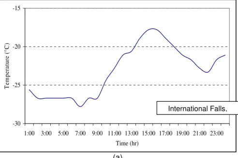
Figure 2a presents the daily temperature variation in International Falls, Minnesota (one of the coldest locations in the US) during the winter season; the data obtained from files for the typical meteorological year (TMY). These data represent temperatures judged
figure, the temperature drops over 10h, between 4PM and 2AM, to stabilize at its lowest level of -27°C for about 7hr during the night. It is worth noting that in several Canadian cities that were part of this project, the temperature could reach lows of -40°C in the winter. Figure 2b presents the average daily temperature variation in a much warmer location: Roanoke, Virginia, during winter. In this location, the temperature drops over about 6hr and it is stable at the low of -1°C for about 3hr. Hence, with dropping temperatures, sealants may be under tensile strain for 6 to 10hr. With constant temperatures and static cracks and joints, the internal stresses may be dissipated by the relaxation of stress over 3 to 7 hrs.
Figure 3 presents the constructed master curve for sealant YY at 4°C, 10°C, and -16°C. The master curve makes it possible to determine the stiffness after 5hr of loading at a reference temperature of -16°C. At the same temperature, the reduction in stiffness after 5hr of creep loading is significant and ranges between 70% and 80% of the calculated stiffness at a loading time of 240s. If the temperature superposition principle is applied, the stiffness at 240s for a given temperature can be used to predict the stiffness after 5 hrs of loading at a temperature of approximately 12°C. Given the variation in sealant response to temperature change, 6°C shift is deemed appropriate.
As previously discussed, the rationale used for setting a maximum threshold limit for the stiffness of crack sealants is different than its use for asphalt binders. A maximum value for stiffness must be set to ensure the flexibility of crack sealant at low temperature after 5hr of creep loading. (a) -30 -25 -20 -15 1:00 3:00 5:00 7:00 9:00 11:00 13:00 15:00 17:00 19:00 21:00 23:00 Time (hr) T em p er at ur e ( °C ) Falls, MN International Falls,
(b)
Figure 2. Variation of Air Temperature for Two Locations: (a) International Falls, MN, and (b) Roanoke, VA
Figure 3. Construction of a Master Curve for Sealant YY from the BBR Test Data Obtained at Three Temperatures
Average Creep Rate
Another method to evaluate the creep behavior from CSBBR data is to determine the average rate of creep and recovery. The creep data versus time were fitted to a power law model. The exponents of the power law model represent the average creep rate. The absolute values of the exponents were then compared. The calculation of the average creep rate for sealant NN at -40°C is illustrated in Figure 4. From the results presented in these figures, it can be estimated that the average rate of creep is 0.34.
-5 -3 -1 1 3 5 1:00 3:00 5:00 7:00 9:00 11:00 13:00 15:00 17:00 19:00 21:00 23:00 Time (hr) T em p er at ur e ( °C ) Roanoke, VA 1 10 100 1000 0.1 1 10 100 1000 10000 100000 Time (s) Stif fn ess (MPa) -16°C -10°C -4°C
Figure 4. Average Creep Rate for Sealant NN at -40°C
Dissipated Energy Ratio
Another indicator considered in this study was the dissipated energy ratio for the sealant during the loading phase. The ratio for dissipated energy reveals the proportion of elasticity and viscosity of the material. A two-term Prony series model was used to
investigate the viscoelastic nature of the sealant. The relationship between strain, , and stress, , can be expressed by the compliance, D(t)= / . The Prony series model describes the creep compliance as follows:
1 2 ( ) ( ) 0 1 2
1
1
1
( )
(1
t)
(1
t)
D t
e
e
E
E
E
τ τ − −=
+
−
+
−
(3) where,D(t) = is the tensile creep compliance at time t; E1, E2 = material constants; and
τ1, τ2 = retardation time.
The parameters of the Prony series are time-independent variables relative to the creep modulus or compliance. Hence, the output of the CSBBR test data was first
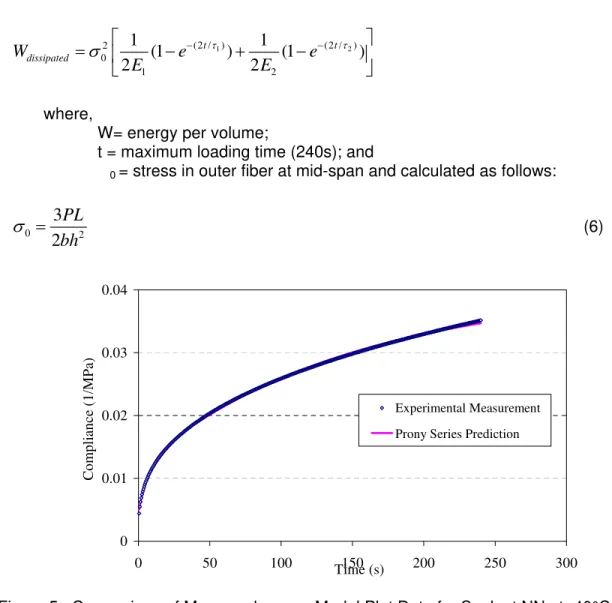
converted to compliances and Prony series parameters were calculated for each test run by fitting the measured compliance to the Prony series model using regression analysis. Figure 5 presents a comparison between measured versus model plot. Since the model fairly fits the experimental data, the Prony series parameters were then used to calculate dissipated and stored energy for each sealant. Equations (4) and (5) present the stored and dissipated energy calculations, respectively (Johansson and Isacsson 1998). The
dissipated energy ratio is calculated as Wdissipated/Wstored.
1 1 2 2 2 ( / ) (2 / ) ( / ) (2 / ) 0 0 1 2 1 1 1 (1 2 ) (1 2 ) 2 t t t t store W e e e e E E E τ τ τ τ
σ
⎡ − − − − ⎤ = ⎢ + − + + − + ⎥ ⎣ ⎦ (4) y = 0.0528x0.3444 R2 = 0.9999 0.01 0.1 11.0E-01 1.0E+00 1.0E+01 1.0E+02 1.0E+03
Time (s) De formatio n (mm) NN_-40°C Power (NN_-40°C)
1 2 (2 / ) (2 / ) 2 0 1 2 1 1 (1 ) (1 ) 2 2 t t dissipated W e e E E τ τ
σ
⎡ − − ⎤ = ⎢ − + − ⎥ ⎣ ⎦ (5) where,W= energy per volume;
t = maximum loading time (240s); and
0 = stress in outer fiber at mid-span and calculated as follows:
0 2
3
2
PL
bh
σ
=
(6)Figure 5. Comparison of Measured versus Model Plot Data for Sealant NN at -40°C Fitted with a Two-Term Prony Series Model
Viscoelastic Behavior and Modeling
The extensive modification used in producing hot-poured crack sealants results in two major differences at low service temperature when compared to asphalt binders. First, at low service temperature, crack sealants may not be in a glassy state, with a glass transition temperature (Tg) reaching as low as -78°C for a very soft sealant such as PP (as measured in this study). Hence, a crack sealant may not experience pure fracture as it is usually encountered in asphalt binders. It is well known that in the glass transition region, a material is brittle and only a small portion of the molecules is in motion or responsive to the applied load. This results in the material responding elastically and linearly to the load. With such a low glass transition temperature, soft sealants may behave as viscoelastic even at low service temperatures (i.e., -4 to -40°C). In fact, the cohesive failure of the soft sealant at low temperature may be attributed to imperfection at the interfaces between the different sealant components rather than to a clear fracture of the material.
0 0.01 0.02 0.03 0.04 0 50 100 Time (s)150 200 250 300 C o mplian ce ( 1/MPa) Experimental Measurement Prony Series Prediction
Second, in contrast to the single-event thermal cracking considered in the
SuperPaveTM binder specification system, cohesive failure of crack sealants is a progressive, localized damage process due to fluctuating stresses and strains in the material and a
buildup of irrecoverable deformations. Therefore, the material response under cyclic thermal loading is of particular interest.
Evaluating the mechanical behavior of crack sealants at low temperature has usually focused on either experimental or laboratory approaches. Since a closed-form solution is not available for a pavement structure incorporating a sealed crack, the mechanical analysis of this problem may only be achieved using numerical methods and has usually been
overlooked in the literature. Although recent work has been presented to evaluate joint seals using finite element (FE) models, researchers have reported difficulties in adopting an accurate constitutive model to describe the mechanical behavior of crack sealants (Khuri and Tons 1993). Reported difficulties include tedious testing procedures and inaccuracy of available models. With the development of a simple creep test at low temperature using the CSBBR test setup, a linear viscoelastic model is presented to describe the mechanical response of crack sealants. This response behavior was further studied utilizing the Kelvin-Voight viscoelastic model simulation. The availability of such a constitutive model would allow for an accurate determination of in-situ crack sealant responses to thermal and traffic loading.
Mechanical Response of Hot-Poured Bituminous-Based Crack Sealant
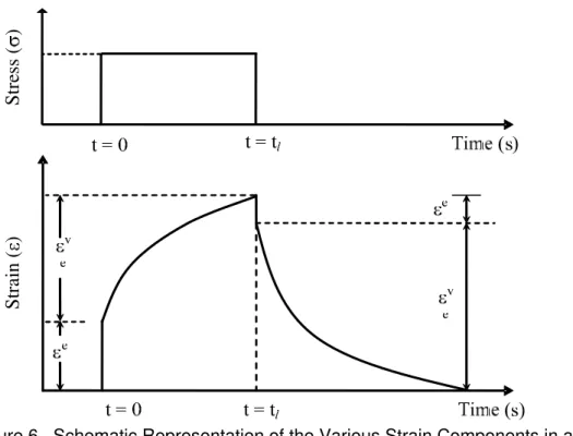
Bituminous crack sealant is a typical viscoelastic material, which exhibits elastic (solid-like) and viscous (fluid-like) mechanical behavior. The elastic response is completely recoverable and it is generally only a small portion of the total response. The viscous portion, which dominates the behavior, dissipates all work energy applied to the material due to the flow within the material (Figure 6). The viscoelastic response due to creep loading is conclusively affected by the percentage of polymers and crumb rubber, which varies in each sealant. In order to fully utilize numerical methods, such as FE analysis, to describe crack sealant behavior, it is important to first characterize the material’s rheological properties using adequate constitutive models. It is also of utmost importance that the utilized models are capable of describing the material’s behavior in order to be incorporated into a numerical presentation.
To predict the performance of hot-poured crack sealants, it is necessary to describe its strain relationship. Viscoelastic theory describes a material’s constitutive stress-strain relationship that requires time to respond to the imposed excitation (delayed
response). When the stress is proportional to the strain at any given frequency and temperature, the material is termed linear viscoelastic. Upon application of a small excitation and depending on the applicable temperature and loading frequency, many materials may be assumed to behave in the linear viscoelastic region. The use of linear viscoelastic theory is somewhat simpler when compared to the use of nonlinear viscoelastic theory, which requires extensive testing for a material’s constitutive behavior to be described.
Strain (
)
Stress (
)
Figure 6. Schematic Representation of the Various Strain Components in an Elasto-Viscoelastic Material
Viscoelastic material properties, including creep compliance as a function of time, are determined from laboratory tests. A curve-fitting function can then be used to describe the linear viscoelastic response with a constitutive equation. Among many candidate models to describe the broad behavior of viscoelastic materials, the Prony series function may be used to fit the creep response, and is mathematically efficient when compared to other models. It has been successfully used for analytical representation of viscoelastic functions of bituminous materials (Park and Kim 2001; Lundström and Isacsson 2004; Kim and Little 2004; Elseifi et al. 2006). It is known as the generalized Voigt model, comprising linear springs and dashpots connected in a particular fashion (Findley et al. 1976). The method described in this report fits a Prony-series expansion to the response of crack sealants obtained from creep testing results. The tests were conducted using the CSBBR setup.
Kelvin-Voigt Viscoelastic Model
The stress-strain behavior of linear viscoelastic materials closely resembles that of models built from discrete elastic (spring) and viscous elements (dashpot) as shown in Figure 7. Of these two basic elements, various models (e.g., Maxwell and Kelvin elements) can be built to describe the viscoelastic response of the material to a given excitation. Testing results are commonly used to verify the applicability of a specific model to predict the performance or behavior of the material under evaluation. To describe the isotropic viscoelastic behavior of hot-poured crack sealants, a generalized Kelvin-Voigt model, which consists of a spring and dashpot connected in series, was selected for this study. In the case of a viscoelastic solid, the creep compliance at time t of a Generalized Kelvin model is given as follows (Park and Shapery 1999):
D
decay place spring are re gene comp retard assoc the P the s Prony Fig beha linear(
E∑
=+
=
K i 0D
D(t)
where, D( Di τi Equation ying expone ed at the star g and the da estrained to rally used to ponent of the dation time c ciated with a Prony-series pan of the te y series term gure 7. Mec It is assum vior, analog rly viscoelas( )
∑
= ∞+ = K i E t where, E Ei i ρ∑
= τ − K 1 / t i(1
-
e
D
i (t) = tensile c = material c = retardatio (7) is also k entials (Figur rt of the cha ashpot of the experiencin o provide an e material (e contributes t a componen should not b est. For exa ms should nochanical Rep med that all ous to the S stic solid can
∑
= − K 1 t ie i E ρ ∞ = equilibr = material c i = relaxatio)
creep compl constants; a on times. nown as a P re 7). Upon in (first term e different K g the same indication o e.g., polymer to the fitting t of the mate be greater th ample, if a cr ot exceed th presentation measureme SuperPaveTM n be express rium modulu constant com on time. liance at tim nd Prony series applying a l m in Equation elvin elemen strain at any of the amoun r) to respond of the mode erial respond han the num reep test is cree.
of a Prony S ents are mad M specificatio sed as follow s; mmonly refe me t; expansion, oad, the exc n [7]) respon nts exhibit co y given time nt of time req d to the impo el in one orde ding to the lo mber of logar conducted fo Series to De de in the line on system. T ws: rred to as re and it repre citation, the ds instantly. onstrained m . The retard quired for a c osed creep l er of time ma oad. The nu ithmic decad or 1000s, the escribe a Vis ear region of The stiffness (8 elaxation stre (7) esents a seri individual sp . In contrast motions as th dation times certain oad. Each agnitude an umber of term des covered e number of scoelastic So f viscoelastic s E
( )
t of a 8) engths; and es of pring t, the hey are d is ms in d by olid cThe glassy compliance represents the short-term behavior (t 0) of the compliance, while E∞ represents the long-term behavior of the modulus. To facilitate the numerical implementation of a Prony series, Equation (8) can be given in a normalized form as follows:
( )
∑
(
)
= − − − = K 1 i t i o i e 1 1 E t Eζ
ρ (9) where, iζ
= ratio between relaxation and initial modulus.To evaluate the Prony series parameters, the three-point CSBBR test was conducted. By applying a constant load to the sealant beam and measuring the center deflection of the beam throughout the test, the creep compliance (D) can be calculated. According to the beam theory and the elastic-viscoelastic correspondence principle, the creep compliance at time (t) can be calculated as follows:
( )
( )
3 3 PL ) t ( bh 4 t t Dδ
σ
ε
= = (10) where,D(t) = time-dependent creep compliance; σ = constant applied stress;
ε(t) = time-dependent strain;
P = constant applied load (980 mN); L = span length (102 mm);
b = beam width (12.7 mm);
h = beam thickness (12.7 mm); and δ = beam deflection at midspan in mm.
While Prony series parameters are normally calculated using the shear modulus data, the resulting creep compliance recorded by the CSBBR can be converted to stiffness using the convolution integral principle:
( ) (
t E t-)
d t D t o =∫
ψ
ψ
(11)Applying Laplace transform to Equation (11), the following equation can be obtained:
( ) ( )
2s
1
s
E
s
D
=
(12) where,s = a Laplace variable.
Schapery and Park (1999) proposed a simplified technique to solve for E(t) as follows:
( )
(
) ( )
( )
(
) ( )
E t s n 1 s E t D s n 1 s D − Γ = + Γ = (13) where,( )
n
Γ
= gamma function; andn = log-log slope of the compliance as a function of time
(
)
(
logt)
d D log d .By applying inverse Laplace and substituting Equation (13) into Equation (12), the relation between the creep and stiffness moduli can be expressed as follows:
( ) ( )
(
) (
)
( )
π
π
n n sin n 1 n 1 1 t E t D = − Γ + Γ = (14)At low temperatures, materials exhibit nearly ideal elastic behavior or behave as a viscoelastic solid. Thus, the relaxation shear modulus G(t) can be expressed using the elastic theory in the following form:
( )
(
( )
)
ν
+ = 1 2 t E t G (15) where,ݒ = a time-independent Poisson’s ratio.
The stiffness modulus calculated from Equation (14) was fitted into Equation (9) to evaluate the Prony series parameters, ζ and ρ. These parameters were also implemented into FE to simulate the deflection response of a sealant as it undergoes creep loading.
Three-Dimensional Finite Element Model
The commercial software ABAQUS version 6.5 was used for FE modeling of crack sealant viscoelastic behavior. Nine-node continuum brick elements, which are appropriate for bending behavior, were used to develop a 3D FE model for the crack sealant beam with a square cross-section of 12.7mm. Figure 8a shows the geometric layout of the 3D FE model, which matches the CSBBR beam dimensions. Because the concentrated load in the CSBBR covers the width of the beam, an equivalent pressure was applied at midspan in the FE beam for a total load of 980mN. The lower end-edges were restrained in both the
Loading is applied in two stages: 980mN for 240s, followed by 30mN for 480s. Although 3D analysis was used, the model took only a few minutes to run because of its simplicity.
The normalized-fitting Prony series parameters, computed in Equation (9), were implemented in the FE for each sealant type at corresponding temperatures. To monitor the variation of the deflection with time, quasi-static analysis was conducted, which considers the time-dependent response of the material; but does not consider the dynamic response of the system, which in this analysis can be neglected. Figure 8b illustrates the model layout after the creep load was applied for a total time of 240s; while Figure 8c illustrates the horizontal stresses.
(a)
(c)
Figure 8. (a) General Description of the FE Model; (b) Vertical Displacement Distribution after 240s Creep Loading; and (c) Horizontal Stress Distribution after 240s Creep Loading
Experimental Design
Fifteen sealants were selected to test at various temperature ranges from +2°C to -40°C. This temperature range covered most of the areas in the Northern America. Each sealant was tested at three temperatures. The selection of testing temperatures is based on the manufacturers’ recommended service temperatures. Sealants were further tested at +/- 6°C of the recommended service temperatures. If the recommended service temperature of the sealant is -40°C, the sealant was tested at -28°C, -34°C, and -40°C. Table 2 shows the experimental factorial design of the test.
Table 2 Experimental Factorial Design of the CSBBR Test Temperature (°C) 2 -4 -10 -16 -22 -28 -34 -40 Sealants QQ QQ QQ EE EE EE ZZ ZZ ZZ YY YY YY AB AB AB VV VV VV UU UU UU AE AE AE DD DD DD MM MM MM WW WW WW NN NN NN AD AD AD PP PP PP BB BB BB
RESULTS AND DISCUSSION
Crack Sealant Bending Beam Rheometer (CSBBR)
BBR Equipment Evaluation
Using the testing procedures summarized in Appendix A, the perceived softest and the stiffest sealants from one manufacturer were tested, along with an intermediate soft sealant from another manufacturer—BB, QQ and NN, respectively. The asphalt beam is supported at both ends by stainless steel half-rounds that are 102mm apart. The specimen, the supports, and the lower part of the test frame are submerged in a constant-temperature fluid bath, which controls the test temperature. During the test, the deflection of the center point of the beam is measured continuously. Sealants BB and NN were tested at -40°C, while sealant QQ was tested at -10°C.
Figure 9 shows time dependency for the load and deflection for sealant QQ. The maximum deflection was 0.7mm after 240s. Figure 10 shows the stiffness calculated using Equation (2) for four replicates of sealant QQ. At 60s, the average stiffness was 154MPa, with a standard deviation of 30.5MPa, and a coefficient of variation (COV) of 19.8%.
For sealant NN that was tested at -40°C, the maximum deflection limit of 6.3mm was reached after 62s of loading (Figure 11). An alternative test was performed with 50% reduction of the applied load. This reduction led to a smaller deflection; but the deflection still remained near the equipment limit (6mm) after 240s. The load was further reduced to 250mN, and a reasonable deflection of approximately 3mm was obtained. With the load of 250mN, the average stiffness after 60s was 12.7±0.60MPa, and the COV was only 4.6%.
Figure 9. Load and Deformation versus Time for Sealant QQ Using the Standard Binder Beam Dimensions at -10°C 0 0.1 0.2 0.3 0.4 0.5 0.6 0.7 0.8 0 20 40 60 80 100 120 140 160 180 200 220 240 Time (s) D ef le ct ion ( m m ) 0 200 400 600 800 1000 1200 Lo ad ( m N ) Deflection Load
Figure 10. Stiffness versus Time for Sealant QQ Using the Standard Binder Beam Dimensions at -10°C
Figure 11. Deflection versus Time for Sealant NN for Three Loadings Using the Standard Binder Beam Dimensions at -40°C
For sealant BB, the deflection limit was reached after only 2s of loading at -40°C (Figure 12). With a load of 250mN, the deflection limit was reached after approximately 40s. When the load was reduced further to 100mN, the deflection was 4.8mm. After 60s, the stiffness was 2.2MPa and the COV was 9.8%. With the 100mN load, however, the deflection was unstable.
1 10 100 1000 1 10 100 1000 Time (s) Stiffness ( M P a ) QQ-1 QQ-2 QQ-3 QQ-4 0 1 2 3 4 5 6 7 0 20 40 60 80 100 120 140 160 180 200 220 240 Time (s) D ef le ct ion ( m m ) 980mN 480mN 250mN
Figure 12. Deflection versus Time for Sealant BB for Three Loading Magnitudes Using the
Standard Binder Beam Dimensions at -40°C
Modifications to the Asphalt Binder Test Procedure
Release Agent for Crack Sealants
To examine the effect of silicone grease material on the BBR results, testing with PG64-22 binder was performed on nine specimens using Mylar strips and on nine specimens using silicone grease. Table 3 shows the results of a t-test analysis (two samples assuming equal variances) conducted on the calculated stiffness values. The results show that the p-values are greater than the 0.05 level of significance. This indicates that there is no evidence of significant difference in the means. Therefore, statistically, the results obtained using the Mylar strips are equivalent to those using the silicone grease. Since silicone grease was proven not to affect the BBR results and was effective in
preventing crack sealants from adhering to the aluminum molds, it was used in all the crack sealant testing conducted in this study, and will be recommended in the final test
specification procedure presented at the end of this report.
Specimen Dimensions
The beam thickness was doubled from 6.35 to 12.7mm, to overcome the
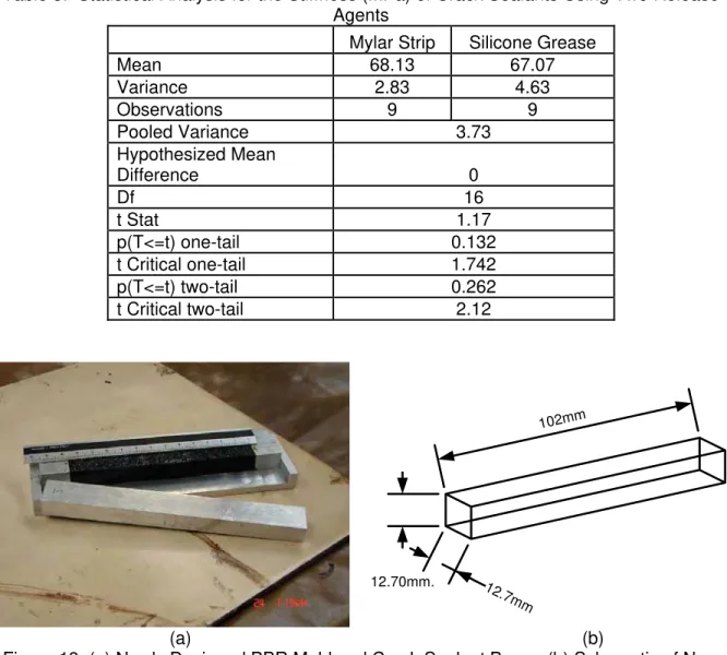
aforementioned problems resulting from the fact that crack sealant materials may exhibit very large deformations during the BBR test. A specimen mold was constructed for this purpose. Figure 13 shows the new mold and the schematic of new beam dimension of crack sealant. 0 1 2 3 4 5 6 7 0 40 80 120 160 200 240 Time (s) D e fl ecti on (mm) 980mN 250mN 100mN
12.70mm.
102mm
12.7mm
Table 3. Statistical Analysis for the Stiffness (MPa) of Crack Sealants Using Two Release Agents
Mylar Strip Silicone Grease
Mean 68.13 67.07 Variance 2.83 4.63 Observations 9 9 Pooled Variance 3.73 Hypothesized Mean Difference 0 Df 16 t Stat 1.17 p(T<=t) one-tail 0.132 t Critical one-tail 1.742 p(T<=t) two-tail 0.262 t Critical two-tail 2.12 (a) (b)
Figure 13. (a) Newly Designed BBR Mold and Crack Sealant Beam; (b) Schematic of New Beam Dimension
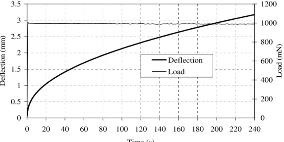
Three replicates of sealant BB were tested using the new beam dimensions. Figure 14 shows the deflection versus time as well as the load versus time for one of the tested specimens. The load and deflection were stable over time. The maximum measured deflection was approximately 3.2mm and the measured stiffness was 6.1MPa, with a COV of 3.5%, after 60s of loading. The above results suggest that a 12.7mm-thick beam for testing hot-poured bituminous-based crack sealant materials was feasible. However,
because of the increase in the beam’s thickness, the deflection due to shear would increase. An analysis to determine the percentage of the deflection due to shear is presented in
Appendix B. This analysis shows that center deflection contributed by shear force is only 4%, which was deemed acceptable (Al-Qadi et al., 2005).
Figure 14. Deflection and Load versus Time for Sealant BB Using the New Beam Thickness of 12.7mm at -40°C
Test Repeatability
The repeatability of testing using the new beam size in CSBBR was studied by testing ten various sealants at -40°C (Sealants BB, CC, GG, HH, LL, MM, NN, PP, SS, and WW) and three sealants (Sealants MM, NN, and PP) at 35°C, 30°C, 28°C, 25°C, and -20°C. In addition, three sealants, described as hard (Sealants QQ, YY, and ZZ), were tested at -10°C. A minimum of three replicates per sealant were tested. Figure 15 shows the measured stiffness after 60s of loading (S60) for the 10 tested sealants at -40°C. Figure 16 shows the measured S60 for sealants MM, NN, and PP versus temperature, while Figure 17 shows the measured S60 for the three sealants tested at -10°C. The highest calculated COV for all tested sealants was found to be 17.1%, while the minimum COV was 1.5%. Figure 18 shows the frequency distribution and the cumulative frequency distribution for the calculated COV. From this figure, it is noted that the most frequent calculated COV was between 6% and 8% (28.6% of the measurements). All measurements had a COV of less than 19%; almost 11% of the measurements had a COV of less than 4%, and almost 72% of the measurements had a COV of less than 10%.
To verify the acceptance of the range of the different results, limits as specified per ASTM C670-03 (Standard Practice for Preparing Precision and Bias Statements for Test Methods for Construction Materials) were checked. All calculated ranges were below the ASTM specified criteria of 3.3 standard deviations when testing three replicates and 3.6 standard deviations when testing four replicates.
0 0.5 1 1.5 2 2.5 3 3.5 0 20 40 60 80 100 120 140 160 180 200 220 240 Time (s) D efl ec tio n (m m ) 0 200 400 600 800 1000 1200 Lo ad ( m N ) Deflection Load