Publisher’s version / Version de l'éditeur:
Vous avez des questions? Nous pouvons vous aider. Pour communiquer directement avec un auteur, consultez la
première page de la revue dans laquelle son article a été publié afin de trouver ses coordonnées. Si vous n’arrivez pas à les repérer, communiquez avec nous à [email protected].
Questions? Contact the NRC Publications Archive team at
[email protected]. If you wish to email the authors directly, please see the first page of the publication for their contact information.
https://publications-cnrc.canada.ca/fra/droits
L’accès à ce site Web et l’utilisation de son contenu sont assujettis aux conditions présentées dans le site LISEZ CES CONDITIONS ATTENTIVEMENT AVANT D’UTILISER CE SITE WEB.
Research Report (National Research Council of Canada. Institute for Research in Construction), 2010-03-29
READ THESE TERMS AND CONDITIONS CAREFULLY BEFORE USING THIS WEBSITE.
https://nrc-publications.canada.ca/eng/copyright
NRC Publications Archive Record / Notice des Archives des publications du CNRC : https://nrc-publications.canada.ca/eng/view/object/?id=c91807a3-96d0-47b9-b7fc-e385209ef566 https://publications-cnrc.canada.ca/fra/voir/objet/?id=c91807a3-96d0-47b9-b7fc-e385209ef566
NRC Publications Archive
Archives des publications du CNRC
For the publisher’s version, please access the DOI link below./ Pour consulter la version de l’éditeur, utilisez le lien DOI ci-dessous.
https://doi.org/10.4224/20374401
Access and use of this website and the material on it are subject to the Terms and Conditions set forth at SIGDERS Air Intrusion Measurements on Mechanically Attached Roofing Systems
http://www.nrc-cnrc.gc.ca/irc
SI GDERS Air I nt rusion M e a sure m e nt s on M e c ha nic a lly At t a c he d Roofing Syst e m s
I R C - R R - 2 9 6
B e a u l i e u , P . ; M o l l e t i , S . ; B a s k a r a n , B . A .M a r c h 2 0 1 0
The material in this document is covered by the provisions of the Copyright Act, by Canadian laws, policies, regulations and international agreements. Such provisions serve to identify the information source and, in specific instances, to prohibit reproduction of materials without
written permission. For more information visit http://laws.justice.gc.ca/en/showtdm/cs/C-42
Les renseignements dans ce document sont protégés par la Loi sur le droit d'auteur, par les lois, les politiques et les règlements du Canada et des accords internationaux. Ces dispositions permettent d'identifier la source de l'information et, dans certains cas, d'interdire la copie de
Page 1 of 116
SIGDERS AIR INTRUSION
MEASUREMENTS ON MECHANICALLY
ATTACHED ROOFING SYSTEMS
P. Beaulieu ,S.Molleti and Bas Baskaran
Research Report No. (IRC-RR 296)
Date of issue: March 29th , 2010
This research report, while not intended for general distribution, may be cited or referenced in other publications
Page 2 of 116
Executive Summary
At the National Research Council of Canada in November 1994, members of the North American roofing community {manufacturers, building owners, industry association and
research agencies} met and agreed that a means of evaluating the effect of dynamic
wind loads on roofing systems was necessary. Thus, a Special Interest Group on
Dynamic Evaluation of Roofing Systems (SIGDERS) was created. The mandate of
SIGDERS joint research program is to carry out generic, pre-competitive research of benefit to all its members. During the Phases 1, 2, 3 and 4 objectives were identified; tasks were developed and executed through approval process by the Steering Committee members. For each of the Phase, SIGDERS deliverables were presented to the members via formal technical meetings and fulfilled all established tasks. Based on the focused effort, recently, SIGDERS made two major contributions to the roofing community by publishing national dynamic wind uplift standard (CSA, 2004) and a guide for wind design of mechanically attached roof assemblies (Baskaran and Smith, 2005). In addition, SIGDEERS’ technology was transferred via more than 100 peer reviewed publications (www.sigders.ca). Currently, SIGDERS is in its Phase V operation.
Objective 2 for the Phase V is “Air Intrusion Quantification of Mechanically Attached Roofing Assemblies”. It has the following tasks:
T1: Demonstrate that wind uplift testing can address the issue of air leakage in roofing.
T2: Measure air intrusion of mechanically attached roofing systems without any barrier/ retarder.
T3: Measure air intrusion of mechanically attached roofing systems with barrier/ retarder.
T4: Measure air intrusion of roofing systems with multilayer insulation arrangements.
To measure the air intrusion in Mechanically Attached Roofing Systems (MARS), a new test laboratory Dynamic Roofing Facility – Air Intrusion (DRF-AI) Lab was developed at the National Research Council of Canada, and a new test protocol was conceptualized. This test protocol has been submitted as a work item to the American Society of Testing and Materials [D08.20.40] towards standard development [Work item WK23684 –
Standard Test Method for Quantification of Air Intrusion in Low Slopped Mechanically Attached Roofing Assemblies].
The DRF-AI test apparatus as shown in Figure 1 consists of two chambers designated as the top chamber and the bottom chamber. The top chamber is movable, while the bottom chamber is fixed to the ground. Both chambers have dimensions of 20 ft (L) X 8 ft (W) X 3 ft (H) [6 m x 2.4 m x 0.91 m]. In the bottom chamber, the roof specimen can be installed and its height can be adjustable using levers. This lever mechanism offer options of the testing roof specimens with different thickness. Test pressures (negative or suction pressures) are applied on the test specimen through a controllable blower connected to the top chamber. To measure the air intrusion into the roofing specimen, the bottom chamber is installed with an airflow measurement system. Three pressure
Page 3 of 116 measuring devices, one on top of the membrane, other above the insulation and at the bottom chamber are installed as shown in Figure 2. To measure the membrane deformation, laser technology is used.
Roofing systems with three different membrane types-modified bituminous (MB), thermoplastic (TP) and thermoset (TS) were tested. Table 1 provides the system details. All systems had common system components and systems with air retarder used a self adhered film as the air retarder component. Layouts for the deck, air retarder, one layer insulation and two layer staggered insulation are shown in Figures 3, 4, 5 and 6 respectively.
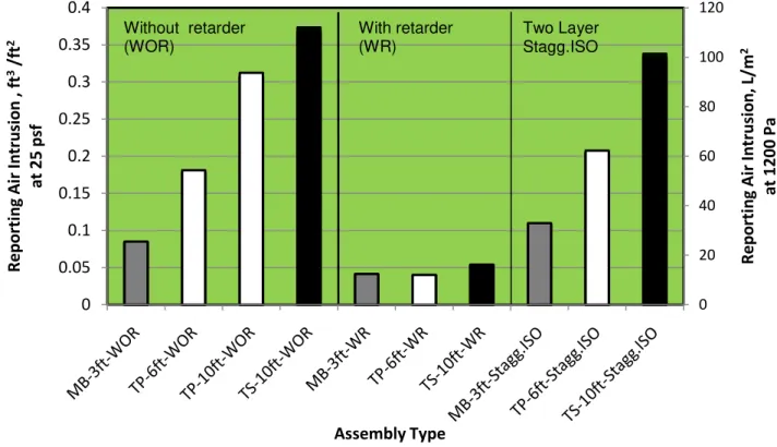
Table 1 summarizes the calculated air intrusion performance of the ten tested systems in terms of the reporting air intrusion volume at 25 psf (1200 Pa) for 60 secs. The reported values in the Table 1 are the average of the two test runs. Figure 7 is the graphical representation of the measured data and categorized as:
Task 2 (WithOut Retarder [WOR]), Task 3 (With Retarder [WR]), and
Task 4 (Two Layer Staggerd Insulation [TLSI].
Based on the test results, the following observations were made:
For all WOR systems same components up to the insulation were used and the only variability was the membrane (width and type). MB system 3ft (1m) had an air intrusion volume of 0.08 ft3/ft2 (25 L/m2), 6ft (2m) TP system had an air intrusion volume of 0.177 ft3/ft2 (54 L/m2), and 10 ft (3.3 m) TP and TS systems measured an air intrusion volume of 0.303 ft3/ft2 (94 L/m2) and 0.366 ft3/ft2 (112 L/m2) respectively. This lead to the formation of a liner trend, i.e as membrane width increases air intrusion volume increases. However, it should be noted as the membrane width changes so as the membrane material type. To validate this linearity, further system investigations are needed by using a same family of TP or TS membrane and varying its sheet widths.
For all three WR systems, a self adhesive air retarder was installed above the deck. Irrespective of the system, they had an average air intrusion volume of 13 L/m2 (0.043 ft3/ft2). Comparing the WR and WOR systems, it is clear that the presence of air retarder minimized air intrusion by 50% in the 3ft (1m) MB system, around 75 % in the 6ft (2m) TP system and around 85% in the 10 ft (3.3 m) TS system. The self adhered film installed on the deck as an air retarder created the first line of defence against the air intrusion through the deck joints. As the retarder had certain air permeance, and also as its layout comprised of seams and fastener penetrations, it could not completely prevent air intrusion but it significantly minimized the volume of air intruding into the WR systems. This indicates that irrespective of the membrane type and width, the presence of air retarder at deck level, if constructed properly minimizes air intrusion into the assembly.
Data from the TLSI systems showed an interesting observation. The air intrusion volume was similar with their respective one layer insulation layout system’s (WOR) i.e. increase in the sheet width increases the volume of air intruding into the roof system. At present there is an assumption that staggered insulation
Page 4 of 116 layout could minimize air intrusion which leads to design practice of eliminating the air retarder component in systems with staggered insulation layout. The measured data fails to support the above assumption and design practice. Comparison of measured air intrusion data of TLSI and WR systems, it can be concluded that contribution of the staggered insulation layout are not same as installing an air retarder above the deck. Component joints are formed at two planes, one at the deck level and other at the insulation level. The staggered insulation layout does not defend the air intrusion through the deck joints and only can dampen the air intrusion through the insulation joints. Failure to control the air intrusion at the deck level (as the air retarder does) allows the air into the system. Providing design options such as staggered insulation layouts can only dampens the flow and redirect the flow path rather than controlling it. Thus why the air intrusion volume was similar with their respective one layer insulation layout. One can analogue this observation with the vapour barrier location in an assembly. If it is not in the warm side of an envelope, having one is similar to having none.
This report also archives the results obtained from the above four tasks as follows: For the Task1, Appendix 1 documents technology transfer activities to
demonstrate that wind uplift testing can address the issue of air leakage in roofing.
Appendices 2, 3 and 4 archive all the measured system response data respectively for the Tasks 2, 3 and 4. The measured data includes membrane pressure, insulation pressure, bottom chamber pressure, membrane deflection, flow rate and the calculated air intrusion volume.
For each system, two test runs or data sets were collected as per the ASTM WK23684, and included in the report with the heading “System # – Data Set #”. For each system, an isometric view of the components used, system layout and a table detailing the components’ nominal physical and mechanical properties are also provided.
Acknowledgement
The presented research is being carried out for a consortium - Special Interest Group for Dynamic Evaluation of Roofing Systems (SIGDERS). SIGDERS was formed from a group of partners who were interested in roofing design. These partners included: Atlas Roofing Corporation, Canadian General-Tower Ltd., Canadian Roofing Contractors’ Association, Carlisle SynTec Incorporated, Dow Roofing Systems, Duro-Last ® Roofing, Inc., Firestone Building Products Company, GAF-Elk Materials Corporation, IKO Industries Ltd., Johns Manville Inc., National Roofing Contractors Association, OMG Roofing Products, Public Works and Government Services Canada, RCI, Inc., Sika Sarnafil, Soprema Canada Inc., Tremco Inc., and Trufast Corporation
Page 5 of 116
References
American Society of Testing and Materials (ASTM) - D08.20.40, Work Item WK23684: Standard Test Method for Quantification of Air Intrusion in Low Sloped Mechanically Attached Roofing Assemblies, 2009.
Baskaran, A. and Smith, T.L (2005), “A Guide for the Wind Design of Mechanically Attached Flexible Membrane Roofs”, www.nrc.gc.ca/virtualstore.
CSA A123.21-04 (2004), “Standard Test Method for the Dynamic Wind Uplift Resistance of Mechanically Attached Membrane Roofing System”, www.csashop.ca
Page 6 of 116
TABLE 1: AIR INTRUSION DATA (IMPERIAL /SI UNITS)
Test No. (YYMM#) System Reporting Volume (ft³/ft²) @ 25 psf for 60 Sec Reporting Volume(L/m2) @ 1200 Pa for 60 Sec Task 2: Without Retarder (WOR)
090201 System 1 (ModBit) No Retarder 1 Layer 4’X4’X2” ISO Fr = 35” Fs= 18” 0.088 25.51 090403 System 2 (PVC) No Retarder 1 Layer 4’X4’X2” ISO Fr = 66” Fs= 12” 0.177 54.31 090807 System 2 -Repeat 0.218 66.70 090908 System 3 (PVC) No Retarder 1 Layer 4’X4’X2” ISO Fr = 114” Fs= 12” 0.303 93.70 090705 System 4 (EPDM) No Retarder 1 Layer 4’X4’X2” ISO Fr = 114” Fs= 12” 0.366 112.05
Task 3: With Retarder (WR) 090202 System 5 (ModBit) Sopravap’r Retarder 1 Layer 4’X4’X2” ISO Fr = 35” Fs= 18” 0.041 12.43 090504 System 6 (PVC) Sopravap’r Retarder 1 Layer 4’X4’X2” ISO Fr = 66” Fs= 12” 0.039 12.03 090706 System 7 (EPDM) Sopravap’r Retarder 1 Layer 4’X4’X2” ISO Fr = 114” Fs= 12” 0.053 16.23
Task 4: With Two Layers Staggered Insulation (TLSI) 091109 System 8 (ModBit) No Retarder 2 Layers 4’X4’X1” ISO Fr = 35” Fs= 18” 0.107 32.97 091110 System 9 (PVC) No Retarder 2 Layers 4’X4’X1” ISO Fr = 66” Fs= 12” 0.203 62.22 100111 System 10 (EPDM) No Retarder 2 Layers 4’X4’X1” ISO Fr = 114” Fs= 12” 0.331 101.40
Page 7 of 116
FIGURE 1: AIR INTRUSION TEST APPARATUS
Page 8 of 116
FIGURE 2: INSTRUMENTATION LAYOUT FOR ALL THE TESTED ASSEMBLIES
P1
P2
P3
P1 = Membrane pressure P2 = Insulation pressure P3 = Bottom chamber pressure D1 = Deflection sensor
LFE = Laminar flow element
Specimen Top Chamber
Page 9 of 116
COMMON SYSTEM CONFIGURATIONS
FIGURE 3: STRUCTURAL STEEL DECK LAYOUT
Page 10 of 116
FIGURE 5: INSULATION LAYOUT
FIGURE 6: MULTIPLE INSULATION LAYOUT
Bottom Layer ISO Layout
Top Layer ISO Layout
Page 11 of 116 0 20 40 60 80 100 120 0 0.05 0.1 0.15 0.2 0.25 0.3 0.35 0.4 Re p o rti n g Ai r In trusi o n , L/ m 2 a t 1 2 0 0 Pa Rep o rti n g Ai r In tr u si o n , ft 3/ft 2 a t 2 5 p sf Assembly Type Without retarder (WOR) With retarder (WR) Two Layer Stagg.ISO
FIGURE 7: REPORTING AIR INTRUSION VOLUME OF THE MECHANICALLY ATTACHED SYSTEMS (SYSTEMS 1 TO 10)
Page 12 of 116
APPENDIX 1: TECHNOLOGY TRANSFER
Molleti, S., Baskaran, B.A., "A New test method for quantifying air leakage of a mechanically-attached roofing assembly," Proceedings of the RCI 22nd International Convention (Orlando, Florida, March 01, 2007), pp. 105-116, March 01, 2007 (NRCC-49438)
Molleti, S., Baskaran, B.A., Ko, K.P., Beaulieu, P., "Air intrusion vs. air leakage - the dilemma for low sloped mechanically attached membrane roofs," Proceedings of the Canadian Symposium on Roofing Technology (Toronto, March 31, 2009), pp. 1-9, April 01, 2009
Molleti, S., Baskaran, B.A., Ko, K.P., Beaulieu, P., "Air leakage vs. air intrusion in low-sloped roofing assemblies," 12th Canadian Conference on Building Science and Technology (Montréal, Quebec, May 06, 2009), pp. 567-578,
Baskaran, B.A., Molleti, S., "How much air is too much? The National Research Council of Canada studies roof system air intrusion," Professional Roofing Magazine, January, pp. 27-32, January 01, 2010
Baskaran, B.A., Molleti, S., "Air intrusion vs. air leakage - the dilemma for low sloped mechanically attached membrane roofs," The Journal of RCI Interface, pp. 4-10, November 01, 2009
Molleti, S., "Newsbrief - roofing researchers to develop new test protocol for quantifying air leakage through low-slope roof assemblies," Construction Innovation, 12, (1), March, pp. 4, March 01, 2007
Page 13 of 116
APPENDIX 2: MEASURE AIR INTRUSION OF MECHANICALLY
ATTACHED ROOFING SYSTEMS WITHOUT ANY BARRIER/
Page 14 of 116
FIGURE A2.1: SYSTEMS 1-MOD BIT: COMPONENTS AND SYSTEM LAYOUT
S = Membrane Seam J = Joist
Page 15 of 116
Page 16 of 116
TABLE A2.1: NOMINAL PHYSICAL AND MECHANICAL PROPERTIES OF THE COMPONENTS FOR SYSTEM 1
Deck
Type Profiled metal
Thickness* 22 Ga
Overall Depth 1.5” (38 mm)
Flute Spacing 5.9” (150 mm)
Joist Spacing 6’ (1828.8 mm)
Source Canam Steel
Insulation
Type Polyiso
Dimensions 4’ x 4’ (1219 mm x 1219 mm) x 2” (51 mm)
Attachment Mechanically fastened, 5 fasteners per board
Compressive Strength as per ASTM D1621-1997 25 psi (170 kPa)
Source IKO
Air/Vapour Barrier/Retarders/Support Board
Type None
Membrane
Type Mod. Bit., Base Sheet and Cap Sheet
Width 39” (991 mm)
Thickness Base Sheet (2.2 mm), Cap Sheet (3.3 mm)
Attachment Base Sheet
Type Mechanical fasteners with Plates
Fastener 3” (76mm), # 14
Fastener Plate 2” (51 mm) dia. Metal Plate
Fastener Row Spacing 35” (889 mm)
Fastener Spacing 18” (152 mm)
Seam
Type Torching Base Sheet Seam
Seaming Width Overlap = 4” (102 mm)
Attachment Cap Sheet
Page 17 of 116
SYSTEM 1 (MOD-BIT-WOR): DATA SET 1 – MEASURED TIME HISTORIES
0 5 10 15 20 25 30 0 1 2 3 4 5 6 7 8 P re s s ure ( psf ) Time (min) 090201-DS1-P1 P1 @ 25 PSF P1 @ 20 PSF P1 @ 15 PSF P1 @ 10 PSF P1 @ 5 PSF 0 5 10 15 20 25 30 0 1 2 3 4 5 6 7 8 P re s s ure ( psf ) Time (min) 090201-DS1-P2 P2 @ 25 PSF P2 @ 20 PSF P2 @ 15 PSF P2 @ 10 PSF P2 @ 5 PSF
Page 18 of 116 0 5 10 15 20 25 30 0 1 2 3 4 5 6 7 8 P re s s ure ( psf ) Time (min) 090201-DS1-P3 P3 @ 25 PSF P3 @ 20 PSF P3 @ 15 PSF P3 @ 10 PSF P3 @ 5 PSF 0 5 10 15 20 25 30 0 1 2 3 4 5 6 7 8 Fl ow ( C FM )
Time (min) 090201-DS1-Flow
FLOW @ 25 PSF FLOW @ 20 PSF FLOW @ 15 PSF FLOW @ 10 PSF FLOW @ 5 PSF
Page 19 of 116 0 10 20 30 40 50 60 70 0 1 2 3 4 5 6 7 8 V ol um e ( ft ^3 )
Time (min) 0900201-DS1- Volume
VOLUME @ 25 PSF VOLUME @ 20 PSF VOLUME @ 15 PSF VOLUME @ 10 PSF VOLUME @ 5 PSF
Page 20 of 116
SYSTEM 1(MOD-BIT-WOR): DATA SET 2 – MEASURED TIME HISTORIES
0 5 10 15 20 25 30 0 1 2 3 4 5 6 7 8 P ressu re (psf) Time (min) 090201-DS2-P1 P1 @ 25 PSF P1 @ 20 PSF P1 @ 15 PSF P1 @ 10 PSF P1 @ 5 PSF 0 5 10 15 20 25 30 0 1 2 3 4 5 6 7 8 P re s s ure ( psf ) Time (min) 090201-DS2-P2 P2 @ 25 PSF P2 @ 20 PSF P2 @ 15 PSF P2 @ 10 PSF P2 @ 5 PSF
Page 21 of 116 0 5 10 15 20 25 30 0 1 2 3 4 5 6 7 8 P re s s ure ( psf ) Time (min) 090201-DS2-P3 P3 @ 25 PSF P3 @ 20 PSF P3 @ 15 PSF P3 @ 10 PSF P3 @ 5 PSF 0 5 10 15 20 25 30 0 1 2 3 4 5 6 7 8 Fl ow ( C FM )
Time (min) 090201-DS2-Flow
FLOW @ 25 PSF FLOW @ 20 PSF FLOW @ 15 PSF FLOW @ 10 PSF FLOW @ 5 PSF
Page 22 of 116 0 10 20 30 40 50 60 70 0 1 2 3 4 5 6 7 8 V ol um e ( ft ^3 )
Time (min) 090201-DS2-Volume
VOLUME @ 25 PSF VOLUME @ 20 PSF VOLUME @ 15 PSF VOLUME @ 10 PSF VOLUME @ 5 PSF
Page 23 of 116
FIGURE A2.3: SYSTEM 2 -THERMOPLASTIC (PVC): COMPONENTS AND SYSTEMS LAYOUT
S = Membrane Seam J = Joist
Page 24 of 116
Page 26 of 116
TABLE A2.2: NOMINAL PHYSICAL AND MECHANICAL PROPERTIES OF THE COMPONENTS FOR SYSTEM 3
Deck
Type Profiled Metal
Thickness* 22 Ga Overall Depth 1 1/2" (38 mm) Flute Spacing 5.9” (150 mm) Joist Spacing 6’ (1828.8) Source CANAM Insulation Type Polyiso Dimensions 4' x 4' (1219 mm x 1219 mm) x 2" (51 mm)
Attachment Mechanically fastened, 5 fasteners per board
Source Sika Sarnafil
Air/Vapor Barrier/Retarders/Support Board
Type None Membrane Type PVC, Single-Ply Width 72" (1828 mm) Thickness 48 mil (1.21 mm) Attachment
Type Mechanical fasteners with plates
Fastener 3" (76mm), #15
Fastener Plates 2 3/8" (60 mm) round plate with barb
Fastener Row Spacing 66” (1676.4 mm)
Fastener Spacing 12” (304 mm)
Seam
Type Hot air welding (One side weld)
Seaming Width Overlap = 5 1/2" (139 mm)
Temperature: 480°C Speed: 2.1m/min
Page 27 of 116
SYSTEM 2(TP-WOR): DATA SET 1 – MEASURED TIME HISTORIES
0 5 10 15 20 25 30 0 1 2 3 4 5 6 7 8 P re s s ure ( psf ) Time (min) 090403-DS1-P1 P1 @ 25 PSF P1 @ 20 PSF P1 @ 15 PSF P1 @ 10 PSF P1 @ 5 PSF 0 5 10 15 20 25 0 1 2 3 4 5 6 7 8 P re s s ure ( psf ) Time (min) 090403-DS1-P2 P2 @ 25 PSF P2 @ 20 PSF P2 @ 15 PSF P2 @ 10 PSF P2 @ 5 PSF
Page 28 of 116 0 5 10 15 20 25 30 0 1 2 3 4 5 6 7 8 P re s s ure ( psf ) Time (min) 090403-DS1-P3 P3 @ 25 PSF P3 @ 20 PSF P3 @ 15 PSF P3 @ 10 PSF P3 @ 5 PSF 0 5 10 15 20 25 30 0 1 2 3 4 5 6 7 8 Fl ow ( C FM )
Time (min) 090403-DS1-Flow
FLOW @ 25 PSF FLOW @ 20 PSF FLOW @ 15 PSF FLOW @ 10 PSF FLOW @ 5 PSF
Page 29 of 116 0 10 20 30 40 50 60 0 1 2 3 4 5 6 7 8 V ol um e ( ft ^3 )
Time (min) 090403-DS1-Volume
VOLUME @ 25 PSF VOLUME @ 20 PSF VOLUME @ 15 PSF VOLUME @ 10 PSF VOLUME @ 5 PSF
Page 30 of 116
SYSTEM 2(TP-WOR): DATA SET 2 – MEASURED TIME HISTORIES
0 5 10 15 20 25 30 0 1 2 3 4 5 6 7 8 P ressu re (psf) Time (min) 090403-DS2-P1 P1 @ 25 PSF P1 @ 20 PSF P1 @ 15 PSF P1 @ 10 PSF P1 @ 5 PSF 0 5 10 15 20 25 30 0 1 2 3 4 5 6 7 8 P re s s ure ( psf ) Time (min) 090403-DS2-P2 P2 @ 25 PSF P2 @ 20 PSF P2 @ 15 PSF P2 @ 10 PSF P2 @ 5 PSF
Page 31 of 116 0 5 10 15 20 25 30 0 1 2 3 4 5 6 7 8 P re s s ure ( psf ) Time (min) 090403-DS2-P3 P3 @ 25 PSF P3 @ 20 PSF P3 @ 15 PSF P3 @ 10 PSF P3 @ 5 PSF 0 5 10 15 20 25 30 0 1 2 3 4 5 6 7 8 Fl ow ( C FM )
Time (min) 090403-DS2-Flow
FLOW @ 25 PSF FLOW @ 20 PSF FLOW @ 15 PSF FLOW @ 10 PSF FLOW @ 5 PSF
Page 32 of 116 0 10 20 30 40 50 60 70 0 1 2 3 4 5 6 7 8 V ol um e ( ft ^3 )
Time (min) 090403-DS2-Volume
VOLUME @ 25 PSF VOLUME @ 20 PSF VOLUME @ 15 PSF VOLUME @ 10 PSF VOLUME @ 5 PSF 0 50 100 150 200 250 300 0 1 2 3 4 5 6 7 8 D e fl e c ti on (m m )
Time (min) 090403-DS2-Deflection
D1 @ 25 PSF D1 @ 20 PSF D1 @ 15 PSF D1 @ 10 PSF D1 @ 5 PSF
Page 33 of 116
SYSTEM 2(TP-WOR): REPEATABILITY – MEASURED TIME HISTORIES
0 5 10 15 20 25 30 0 1 2 3 4 5 6 7 8 P ressu re (psf) Time (min) 090807-DS1-P1 P1 @ 25 PSF P1 @ 20 PSF P1 @ 15 PSF P1 @ 10 PSF P1 @ 5 PSF 0 5 10 15 20 25 30 0 1 2 3 4 5 6 7 8 P re s s ure ( psf ) Time (min) 090807-DS1-P2 P2 @ 25 PSF P2 @ 20 PSF P2 @ 15 PSF P2 @ 10 PSF P2 @ 5 PSF
Page 34 of 116 0 5 10 15 20 25 30 0 1 2 3 4 5 6 7 8 P re s s ure ( psf ) Time (min) 090807-DS1-P3 P3 @ 25 PSF P3 @ 20 PSF P3 @ 15 PSF P3 @ 10 PSF P3 @ 5 PSF 0 5 10 15 20 25 30 0 1 2 3 4 5 6 7 8 Fl ow ( C FM )
Time (min) 090807-DS1-Flow
FLOW @ 25 PSF FLOW @ 20 PSF FLOW @ 15 PSF FLOW @ 10 PSF FLOW @ 5 PSF
Page 35 of 116 0 10 20 30 40 50 60 70 0 1 2 3 4 5 6 7 8 V ol um e ( ft ^3 )
Time (min) 090807-DS1-Volume
VOLUME @ 25 PSF VOLUME @ 20 PSF VOLUME @ 15 PSF VOLUME @ 10 PSF VOLUME @ 5 PSF 0 50 100 150 200 250 300 0 1 2 3 4 5 6 7 8 D e fl e c ti on (m m )
Time (min) 090807-DS1-Deflection
D1 @ 25 PSF D1 @ 20 PSF D1 @ 15 PSF D1 @ 10 PSF D1 @ 5 PSF
Page 36 of 116
FIGURE A2.5: SYSTEM 3- THERMOPLASTIC (PVC): COMPONENTS AND SYSTEMS LAYOUT
S = Membrane Seam J = Joist
Page 37 of 116
SYSTEM 3(TP-WOR): DATA SET 1 – MEASURED TIME HISTORIES
0 5 10 15 20 25 30 0 1 2 3 4 5 6 7 8 P ressu re (psf) Time (min) 090908-DS1-P1 P1 @ 25 PSF P1 @ 20 PSF P1 @ 15 PSF P1 @ 10 PSF P1 @ 5 PSF 0 5 10 15 20 25 0 1 2 3 4 5 6 7 8 P re s s ure ( psf ) Time (min) 090708-DS1-P2 P2 @ 25 PSF P2 @ 20 PSF P2 @ 15 PSF P2 @ 10 PSF P2 @ 5 PSF
Page 38 of 116 0 5 10 15 20 25 30 0 1 2 3 4 5 6 7 8 P re s s ure ( psf ) Time (min) 090708-DS1-P3 P3 @ 25 PSF P3 @ 20 PSF P3 @ 15 PSF P3 @ 10 PSF P3 @ 5 PSF 0 5 10 15 20 25 30 0 1 2 3 4 5 6 7 8 Fl ow ( C FM )
Time (min) 090708-DS1-FLOW
FLOW @ 25 PSF FLOW @ 20 PSF FLOW @ 15 PSF FLOW @ 10 PSF FLOW @ 5 PSF
Page 39 of 116 0 10 20 30 40 50 60 0 1 2 3 4 5 6 7 8 V ol um e ( ft ^3 )
Time (min) 090708-DS1-VOLUME
VOLUME @ 25 PSF VOLUME @ 20 PSF VOLUME @ 15 PSF VOLUME @ 10 PSF VOLUME @ 5 PSF 0 50 100 150 200 250 300 0 1 2 3 4 5 6 7 8 P re s s ure ( psf )
Time (min) 090708-DS1-DEFLECTION
D1 @ 25 PSF D1 @ 20 PSF D1 @ 15 PSF D1 @ 10 PSF D1 @ 5 PSF
Page 40 of 116
SYSTEM 3(TP-WOR): DATA SET 2 – MEASURED TIME HISTORIES
0 5 10 15 20 25 30 0 1 2 3 4 5 6 7 8 P ressu re (psf) Time (min) 090908-DS2-P1 P1 @ 25 PSF P1 @ 20 PSF P1 @ 15 PSF P1 @ 10 PSF P1 @ 5 PSF 0 5 10 15 20 25 0 1 2 3 4 5 6 7 8 P re s s ure ( psf ) Time (min) 090908-DS2-P2 P2 @ 25 PSF P2 @ 20 PSF P2 @ 15 PSF P2 @ 10 PSF P2 @ 5 PSF
Page 41 of 116 0 5 10 15 20 25 30 0 1 2 3 4 5 6 7 8 P re s s ure ( psf ) Time (min) 090908-DS2-P3 P3 @ 25 PSF P3 @ 20 PSF P3 @ 15 PSF P3 @ 10 PSF P3 @ 5 PSF 0 5 10 15 20 25 30 0 1 2 3 4 5 6 7 8 Fl ow ( C FM )
Time (min) 090908-DS2-FLOW
FLOW @ 25 PSF FLOW @ 20 PSF FLOW @ 15 PSF FLOW @ 10 PSF FLOW @ 5 PSF
Page 42 of 116 0 10 20 30 40 50 60 0 1 2 3 4 5 6 7 8 V ol um e ( ft ^3 )
Time (min) 0909108-DS2-VOLUME
VOLUME @ 25 PSF VOLUME @ 20 PSF VOLUME @ 15 PSF VOLUME @ 10 PSF VOLUME @ 5 PSF 0 50 100 150 200 250 300 0 1 2 3 4 5 6 7 8 D e fl e c ti on (m m )
Time (min) 090908-DS2-DEFLECTION
D1 @ 25 PSF D1 @ 20 PSF D1 @ 15 PSF D1 @ 10 PSF D1 @ 5 PSF
Page 43 of 116
FIGURE A2.6: SYSTEM 4 - THERMOSET (EPDM): COMPONENTS AND SYSTEM LAYOUT
240 in.
S = Membrane Seam J = Joist
Page 44 of 116
Page 46 of 116
TABLE A2.3: NOMINAL PHYSICAL AND MECHANICAL PROPERTIES OF THE COMPONENTS FOR SYSTEM 4
Deck
Type Profiled Metal
Thickness* 22 Ga Overall Depth 1 1/2" (38 mm) Flute Spacing 5.9” (150 mm) Joist Spacing 6’ (1828.8) Source CANAM Insulation Type Polyiso Dimensions 4' x 4' (1219 mm x 1219 mm) x 2" (51 mm)
Attachment Mechanically fastened, 5 fasteners per board
Source FireStone
Air/Vapor Barrier/Retarders/Support Board
Type None
Membrane
Type EPDM, Single-Ply (FireStone)
Width 120”(3048 mm)
Thickness 45 mil (1.14 mm)
Attachment
Type Mechanical fasteners Batten Strip
Fastener 3" (76mm), #15
Batten Strip ¾” Polymer Batten Strip
Fastener Row Spacing 114” (2895.6 mm)
Fastener Spacing 12” (304 mm)
Seam
Type Taped (6”)
Seaming Width Overlap = 5 1/2" (139 mm)
Page 47 of 116
SYSTEM 4(TS-WOR): DATA SET 1 – MEASURED TIME HISTORIES
0 5 10 15 20 25 30 0 1 2 3 4 5 6 7 8 P re s s ure ( psf ) Time (min) 090705-DS1-P1 P1 @ 25 PSF P1 @ 20 PSF P1 @ 15 PSF P1 @ 10 PSF P1 @ 5 PSF 0 5 10 15 20 25 30 0 1 2 3 4 5 6 7 8 P re s s ure ( psf ) Time (min) 090705-DS1-P2 P2 @ 25 PSF P2 @ 20 PSF P2 @ 15 PSF P2 @ 10 PSF P2 @ 5 PSF
Page 48 of 116 0 5 10 15 20 25 30 0 1 2 3 4 5 6 7 8 P re s s ure ( psf ) Time (min) 090705-DS1-P3 P3 @ 25 PSF P3 @ 20 PSF P3 @ 15 PSF P3 @ 10 PSF P3 @ 5 PSF 0 5 10 15 20 25 30 0 1 2 3 4 5 6 7 8 Fl ow ( C FM )
Time (min) 090705-DS1-Flow
FLOW @ 25 PSF FLOW @ 20 PSF FLOW @ 15 PSF FLOW @ 10 PSF FLOW @ 5 PSF
Page 49 of 116 0 10 20 30 40 50 60 70 0 1 2 3 4 5 6 7 8 V ol um e ( ft ^3 )
Time (min) 090705-DS1-Volume
VOLUME @ 25 PSF VOLUME @ 20 PSF VOLUME @ 15 PSF VOLUME @ 10 PSF VOLUME @ 5 PSF
Page 50 of 116
SYSTEM 4(TS-WOR): DATA SET 2 – MEASURED TIME HISTORIES
0 5 10 15 20 25 30 0 1 2 3 4 5 6 7 8 Pre s s ure ( ps f) Time (min) 090705-DS2-P1 P1 @ 25 PSF P1 @ 20 PSF P1 @ 15 PSF P1 @ 10 PSF P1 @ 5 PSF 0 5 10 15 20 25 30 0 1 2 3 4 5 6 7 8 Pre s s ure ( ps f) Time (min) 090705-DS2-P2 P2 @ 25 PSF P2 @ 20 PSF P2 @ 15 PSF P2 @ 10 PSF P2 @ 5 PSF
Page 51 of 116 0 5 10 15 20 25 30 0 1 2 3 4 5 6 7 8 Pre s s ure ( ps f) Time (min) 090705-DS2-P3 P3 @ 25 PSF P3 @ 20 PSF P3 @ 15 PSF P3 @ 10 PSF P3 @ 5 PSF 0 5 10 15 20 25 30 0 1 2 3 4 5 6 7 8 Fl ow ( C FM )
Time (min) 090705-DS2-Flow
FLOW @ 25 PSF FLOW @ 20 PSF FLOW @ 15 PSF FLOW @ 10 PSF FLOW @ 5 PSF
Page 52 of 116 0 10 20 30 40 50 60 70 0 1 2 3 4 5 6 7 8 Vol ume (f t^ 3 )
Time (min) 090705-DS2-Volume
VOLUME @ 25 PSF VOLUME @ 20 PSF VOLUME @ 15 PSF VOLUME @ 10 PSF VOLUME @ 5 PSF 0 50 100 150 200 250 300 0 1 2 3 4 5 6 7 8 D e fl e c ti on (m m )
Time (min) 090705-DS2-Deflection
D1 @ 25 PSF D1 @ 20 PSF D1 @ 15 PSF D1 @ 10 PSF D1 @ 5 PSF
Page 53 of 116
TABLE A2.4: SUMMARY OF THE MEASURE DATA
Test No. (YYMM#) System Total Volume (ft³) @ 25 psf Membrane Deflection (In) @ 25 psf Reporting Volume (ft³/ft²) @ 25 psf for 60 Sec Task 2: Without Retarder (WOR)
090201 System 1 (ModBit) No Retarder 1 Layer 4’X4’X2” ISO Fr = 35” Fs= 18” 15.11 N/A 0.088 090403 System 2 (PVC) No Retarder 1 Layer 4’X4’X2” ISO Fr = 66” Fs= 12” 37.22 N/A 0.177 090807 System 2 -Repeat 37.26 6.78 0.218 090908 System 3 (PVC) No Retarder 1 Layer 4’X4’X2” ISO Fr = 114” Fs= 12” 50.65 10.44 0.303 090705 System 4 (EPDM) No Retarder 1 Layer 4’X4’X2” ISO Fr = 114” Fs= 12” 59.54 11.04 0.366 Test No. (YYMM#) System Total Volume (L) @ 1200 Pa Membrane Deflection (mm) @ 1200 Pa Reporting Volume(L/m2) @ 1200 Pa for 60 Sec Task 2: Without Retarder (WOR)
090201 System 1 (ModBit) No Retarder 1 Layer 4’X4’X2” ISO Fr = 35” Fs= 18” 427.8 N/A 25.51 090403 System 2 ( PVC) No Retarder 1 Layer 4’X4’X2” ISO Fr = 66” Fs= 12” 1053.9 N/A 54.31 090807 System 3 -Repeat 1055.1 172 66.70 090908 System 4 (PVC) No Retarder 1 Layer 4’X4’X2” ISO Fr = 114” Fs= 12” 1434.2 265 93.70 090705 System 5 ( EPDM) No Retarder 1 Layer 4’X4’X2” ISO Fr = 114” Fs= 12” 1685.9 280 112.05
Page 54 of 116
APPENDIX 3: MEASURE AIR INTRUSION OF MECHANICALLY
ATTACHED ROOFING SYSTEMS WITH ANY BARRIER/ RETARDER
Page 55 of 116
FIGURE A3.1: SYSTEMS 5-MOD BIT: COMPONENTS AND SYSTEM LAYOUT
Air Retarder
S = Membrane Seam J = Joist
Page 56 of 116
Page 57 of 116
TABLE A3.1: NOMINAL PHYSICAL AND MECHANICAL PROPERTIES OF THE COMPONENTS FOR SYSTEM 5
Deck
Type Profiled metal
Thickness* 22 Ga
Overall Depth 1.5” (38 mm)
Flute Spacing 5.9” (150 mm)
Joist Spacing 6’ (1828.8 mm)
Source Canam Steel
Insulation
Type Polyiso
Dimensions 4’ x 4’ (1219 mm x 1219 mm) x 2” (51 mm)
Attachment Mechanically fastened, 5 fasteners per board
Compressive Strength as per ASTM D1621-1997 25 psi (170 kPa)
Source IKO
Air/Vapour Barrier/Retarders/Support Board
Type 3 mil SOPRAVAPOR
Membrane
Type Mod. Bit., Base Sheet and Cap Sheet
Width 39” (991 mm)
Thickness Base Sheet (2.2 mm), Cap Sheet (3.3 mm)
Attachment Base Sheet
Type Mechanical fasteners with Plates
Fastener 3” (76mm), # 14
Fastener Plate 2” (51 mm) dia. Metal Plate
Fastener Row Spacing 35” (889 mm)
Fastener Spacing 18” (152 mm)
Seam
Type Torching Base Sheet Seam
Seaming Width Overlap = 4” (102 mm)
Attachment Cap Sheet
Page 58 of 116
SYSTEM 5(MOD-BIT-WR): DATA SET 1 – MEASURED TIME HISTORIES
0 5 10 15 20 25 30 0 1 2 3 4 5 6 7 8 P re s s ure ( psf ) Time (min) 090202-DS1-P1 P1 @ 25 PSF P1 @ 20 PSF P1 @ 15 PSF P1 @ 10 PSF P1 @ 5 PSF 0 5 10 15 20 25 30 0 1 2 3 4 5 6 7 8 P re s s ure ( psf ) Time (min) 090202-DS1-P2 P2 @ 25 PSF P2 @ 20 PSF P2 @ 15 PSF P2 @ 10 PSF P2 @ 5 PSF
Page 59 of 116 0 5 10 15 20 25 30 0 1 2 3 4 5 6 7 8 P re s s ure ( psf ) Time (min) 090202-DS1-P3 P3 @ 25 PSF P3 @ 20 PSF P3 @ 15 PSF P3 @ 10 PSF P3 @ 5 PSF 0 5 10 15 20 25 30 0 1 2 3 4 5 6 7 8 Fl ow ( C FM )
Time (min) 090202-DS1-Flow
FLOW @ 25 PSF FLOW @ 20 PSF FLOW @ 15 PSF FLOW @ 10 PSF FLOW @ 5 PSF
Page 60 of 116 0 10 20 30 40 50 60 0 1 2 3 4 5 6 7 8 V ol um e ( ft ^3 )
Time (min) 090202-DS1-Volume
VOLUME @ 25 PSF VOLUME @ 20 PSF VOLUME @ 15 PSF VOLUME @ 10 PSF VOLUME @ 5 PSF
Page 61 of 116
SYSTEM 5(MOD-BIT-WR): DATA SET 2 – MEASURED TIME HISTORIES
0 5 10 15 20 25 30 0 1 2 3 4 5 6 7 8 P re s s ure ( psf ) Time (min) 090202-DS2-P1 P1 @ 25 PSF P1 @ 20 PSF P1 @ 15 PSF P1 @ 10 PSF P1 @ 5 PSF 0 5 10 15 20 25 30 0 1 2 3 4 5 6 7 8 P re s s ure ( psf ) Time (min) 090202-DS2-P2 P2 @ 25 PSF P2 @ 20 PSF P2 @ 15 PSF P2 @ 10 PSF P2 @ 5 PSF
Page 62 of 116 0 5 10 15 20 25 30 0 1 2 3 4 5 6 7 8 P re s s ure ( psf ) Time (min) 090202-DS2-P3 P3 @ 25 PSF P3 @ 20 PSF P3 @ 15 PSF P3 @ 10 PSF P3 @ 5 PSF 0 5 10 15 20 25 30 0 1 2 3 4 5 6 7 8 Fl ow ( C FM )
Time (min) 090202-DS2-Flow
FLOW @ 25 PSF FLOW @ 20 PSF FLOW @ 15 PSF FLOW @ 10 PSF FLOW @ 5 PSF
Page 63 of 116 0 10 20 30 40 50 60 0 1 2 3 4 5 6 7 8 V ol um e ( ft ^3 )
Time (min) 090202-DS2-Volume
VOLUME @ 25 PSF VOLUME @ 20 PSF VOLUME @ 15 PSF VOLUME @ 10 PSF VOLUME @ 5 PSF
Page 64 of 116
FIGURE A3.3: SYSTEM 6 -THERMOPLASTIC (PVC): COMPONENTS AND SYSTEMS LAYOUT
S = Membrane Seam J = Joist
Page 65 of 116
Page 67 of 116
TABLE A3.2: NOMINAL PHYSICAL AND MECHANICAL PROPERTIES OF THE COMPONENTS FOR SYSTEM 6
Deck
Type Profiled Metal
Thickness* 22 Ga Overall Depth 1 1/2" (38 mm) Flute Spacing 5.9” (150 mm) Joist Spacing 6’ (1828.8) Source CANAM Insulation Type Polyiso Dimensions 4' x 4' (1219 mm x 1219 mm) x 2" (51 mm)
Attachment Mechanically fastened, 5 fasteners per board
Source Sika Sarnafil
Air/Vapor Barrier/Retarders/Support Board
Type 3 mil Sopravapor
Membrane
Type PVC, Single-Ply
Width 72" (1828 mm)
Thickness 48 mil (1.21 mm)
Attachment
Type Mechanical fasteners with plates
Fastener 3" (76mm), #15
Fastener Plates 2 3/8" (60 mm) round plate with barb
Fastener Row Spacing 66” (1676.4 mm)
Fastener Spacing 12” (304 mm)
Seam
Type Hot air welding (One side weld)
Seaming Width Overlap = 5 1/2" (139 mm)
Temperature: 480°C Speed: 2.1m/min
Page 68 of 116
SYSTEM 6(TP-WR): DATA SET 1 – MEASURED TIME HISTORIES
0 5 10 15 20 25 30 0 1 2 3 4 5 6 7 8 P ressu re (psf) Time (min) 090504-DS1-P1 P1 @ 25 PSF P1 @ 20 PSF P1 @ 15 PSF P1 @ 10 PSF P1 @ 5 PSF 0 5 10 15 20 25 30 0 1 2 3 4 5 6 7 8 P re s s ure ( psf ) Time (min) 090504-DS1-P2 P2 @ 25 PSF P2 @ 20 PSF P2 @ 15 PSF P2 @ 10 PSF P2 @ 5 PSF
Page 69 of 116 0 5 10 15 20 25 30 0 1 2 3 4 5 6 7 8 P re s s ure ( psf ) Time (min) 090504-DS1-P3 P3 @ 25 PSF P3 @ 20 PSF P3 @ 15 PSF P3 @ 10 PSF P3 @ 5 PSF 0 5 10 15 20 25 30 0 1 2 3 4 5 6 7 8 Fl ow ( C FM )
Time (min) 090504-DS1-Flow
FLOW @ 25 PSF FLOW @ 20 PSF FLOW @ 15 PSF FLOW @ 10 PSF FLOW @ 5 PSF
Page 70 of 116 0 10 20 30 40 50 60 70 0 1 2 3 4 5 6 7 8 V ol um e ( ft ^3 )
Time (min) 090504-DS1-Volume
VOLUME @ 25 PSF VOLUME @ 20 PSF VOLUME @ 15 PSF VOLUME @ 10 PSF VOLUME @ 5 PSF
Page 71 of 116
SYSTEM 6(TP-WR): DATA SET 2 – MEASURED TIME HISTORIES
0 5 10 15 20 25 30 0 1 2 3 4 5 6 7 8 P re s s ure ( psf ) Time (min) 090504-DS2-P1 P1 @ 25 PSF P1 @ 20 PSF P1 @ 15 PSF P1 @ 10 PSF P1 @ 5 PSF 0 5 10 15 20 25 30 0 1 2 3 4 5 6 7 8 P re s s ure ( psf ) Time (min) 090504-DS2-P2 P2 @ 25 PSF P2 @ 20 PSF P2 @ 15 PSF P2 @ 10 PSF P2 @ 5 PSF
Page 72 of 116 0 5 10 15 20 25 30 0 1 2 3 4 5 6 7 8 P re s s ure ( psf ) Time (min) 090504-DS2-P3 P3 @ 25 PSF P3 @ 20 PSF P3 @ 15 PSF P3 @ 10 PSF P3 @ 5 PSF 0 5 10 15 20 25 30 0 1 2 3 4 5 6 7 8 Fl ow ( C FM )
Time (min) 090504-DS2-Flow
FLOW @ 25 PSF FLOW @ 20 PSF FLOW @ 15 PSF FLOW @ 10 PSF FLOW @ 5 PSF
Page 73 of 116 0 10 20 30 40 50 60 70 0 1 2 3 4 5 6 7 8 V ol um e ( ft ^3 )
Time (min) 090504-DS2-Volume
VOLUME @ 25 PSF VOLUME @ 20 PSF VOLUME @ 15 PSF VOLUME @ 10 PSF VOLUME @ 5 PSF 0 50 100 150 200 250 300 0 1 2 3 4 5 6 7 8 D e fl e c ti on (m m )
Time (min) 090504-DS2-Deflection
D1 @ 25 PSF D1 @ 20 PSF D1 @ 15 PSF D1 @ 10 PSF D1 @ 5 PSF
Page 74 of 116
FIGURE A3.5: SYSTEM 7 - THERMOSET (EPDM): COMPONENTS AND SYSTEM LAYOUT
S = Membrane Seam J = Joist
Page 75 of 116
Page 77 of 116
TABLE A3.3: NOMINAL PHYSICAL AND MECHANICAL PROPERTIES OF THE COMPONENTS FOR SYSTEM 7
Deck
Type Profiled Metal
Thickness* 22 Ga Overall Depth 1 1/2" (38 mm) Flute Spacing 5.9” (150 mm) Joist Spacing 6’ (1828.8) Source CANAM Insulation Type Polyiso Dimensions 4' x 4' (1219 mm x 1219 mm) x 2" (51 mm)
Attachment Mechanically fastened, 5 fasteners per board
Source FireStone
Air/Vapor Barrier/Retarders/Support Board
Type Sopravapor
Membrane
Type EPDM, Single-Ply (FireStone)
Width 120”(3048 mm)
Thickness 45 mil (1.14 mm)
Attachment
Type Mechanical fasteners Batten Strip
Fastener 3" (76mm), #15
Batten Strip ¾” Polymer Batten Strip
Fastener Row Spacing 114” (2895.6 mm)
Fastener Spacing 12” (304 mm)
Seam
Type Taped (6”)
Seaming Width Overlap = 5 1/2" (139 mm)
Page 78 of 116
SYSTEM 7(TS-WR): DATA SET 1 – MEASURED TIME HISTORIES
0 5 10 15 20 25 30 0 1 2 3 4 5 6 7 8 P re s s ure ( psf ) Time (min) 090706-DS1-P1 P1 @ 25 PSF P1 @ 20 PSF P1 @ 15 PSF P1 @ 10 PSF P1 @ 5 PSF 0 5 10 15 20 25 30 0 1 2 3 4 5 6 7 8 P re s s ure ( psf ) Time (min) 090706-DS1-P2 P2 @ 25 PSF P2 @ 20 PSF P2 @ 15 PSF P2 @ 10 PSF P2 @ 5 PSF
Page 79 of 116 0 5 10 15 20 25 30 0 1 2 3 4 5 6 7 8 P re s s ure ( psf ) Time (min) 090706-DS1-P3 P3 @ 25 PSF P3 @ 20 PSF P3 @ 15 PSF P3 @ 10 PSF P3 @ 5 PSF 0 5 10 15 20 25 30 0 1 2 3 4 5 6 7 8 Fl ow ( C FM )
Time (min) 090706-DS1-Flow
FLOW @ 25 PSF FLOW @ 20 PSF FLOW @ 15 PSF FLOW @ 10 PSF FLOW @ 5 PSF
Page 80 of 116 0 10 20 30 40 50 60 70 0 1 2 3 4 5 6 7 8 V ol um e ( ft ^3 )
Time (min) 090706-DS1-Volume
VOLUME @ 25 PSF VOLUME @ 20 PSF VOLUME @ 15 PSF VOLUME @ 10 PSF VOLUME @ 5 PSF 0 50 100 150 200 250 300 0 1 2 3 4 5 6 7 8 D e fl e c ti on (m m )
Time (min) 090706-DS1-Deflection
D1 @ 25 PSF D1 @ 20 PSF D1 @ 15 PSF D1 @ 10 PSF D1 @ 5 PSF
Page 81 of 116
SYSTEM 7 (TS-WR): DATA SET 2 – MEASURED TIME HISTORIES
0 5 10 15 20 25 30 0 1 2 3 4 5 6 7 8 P re s s ure ( psf ) Time (min) 090706-DS2-P1 P1 @ 25 PSF P1 @ 20 PSF P1 @ 15 PSF P1 @ 10 PSF P1 @ 5 PSF 0 5 10 15 20 25 30 0 1 2 3 4 5 6 7 8 P re s s ure ( psf ) Time (min) 090706-DS2-P2 P2 @ 25 PSF P2 @ 20 PSF P2 @ 15 PSF P2 @ 10 PSF P2 @ 5 PSF
Page 82 of 116 0 5 10 15 20 25 30 0 1 2 3 4 5 6 7 8 P re s s ure ( psf ) Time (min) 090706-DS2-P3 P3 @ 25 PSF P3 @ 20 PSF P3 @ 15 PSF P3 @ 10 PSF P3 @ 5 PSF 0 5 10 15 20 25 30 0 1 2 3 4 5 6 7 8 Fl ow ( C FM )
Time (min) 090706-DS2-Flow
FLOW @ 25 PSF FLOW @ 20 PSF FLOW @ 15 PSF FLOW @ 10 PSF FLOW @ 5 PSF
Page 83 of 116 0 10 20 30 40 50 60 0 1 2 3 4 5 6 7 8 V ol um e ( ft ^3 )
Time (min) 090706-DS2-Volume
VOLUME @ 25 PSF VOLUME @ 20 PSF VOLUME @ 15 PSF VOLUME @ 10 PSF VOLUME @ 5 PSF 0 50 100 150 200 250 300 0 1 2 3 4 5 6 7 8 D e fl e c ti on (m m )
Time (min) 090706-DS2-Deflection
D1 @ 25 PSF D1 @ 20 PSF D1 @ 15 PSF D1 @ 10 PSF D1 @ 5 PSF
Page 84 of 116
TABLE A3.4: SUMMARY OF THE MEASURE DATA
Test No. (YYMM#) System Total Volume (ft³) @ 25 psf Membrane Deflection (In) @ 25 psf Reporting Volume (ft³/ft²) @ 25 psf for 60 Sec Task 3: With Retarder (WR)
090202 System 5 (ModBit) Sopravap’r Retarder 1 Layer 4’X4’X2” ISO Fr = 35” Fs= 18” 13.63 N/A 0.041 090504 System 6 (PVC) Sopravap’r Retarder 1 Layer 4’X4’X2” ISO Fr = 66” Fs= 12” 7.51 5.26 0.039 090706 System 7 (EPDM) Sopravap’r Retarder 1 Layer 4’X4’X2” ISO Fr = 114” Fs= 12” 13.13 3.10 0.053 Test No. (YYMM#) System Total Volume (L) @ 1200 Pa Membrane Deflection (mm) @ 1200 Pa Reporting Volume(L/m2) @ 1200 Pa for 60 Sec Task 3: With Retarder (WR)
090202 System 6 ( ModBit) Sopravap’r Retarder 1 Layer 4’X4’X2” ISO Fr = 35” Fs= 18” 385.9 N/A 12.43 090504 System 7 ( PVC) Sopravap’r Retarder 1 Layer 4’X4’X2” ISO Fr = 66” Fs= 12” 212.6 133 12.03 090706 System 8 ( EPDM) Sopravap’r Retarder 1 Layer 4’X4’X2” ISO Fr = 114” Fs= 12” 371.8 78 16.23
Page 85 of 116
APPENDIX 4: MEASURE AIR INTRUSION OF ROOFING
SYSTEMS WITH MULTILAYER INSULATION ARRANGEMENTS.
Page 86 of 116
FIGURE A4.1: SYSTEM 8: MOD-BIT – COMPONENTS AND SYSTEM LAYOUT
(Two layer staggered arrangement)
Page 87 of 116
Page 89 of 116
TABLE A4.1: NOMINAL PHYSICAL AND MECHANICAL PROPERTIES OF THE COMPONENTS FOR SYSTEM 8
Deck
Type Profiled metal
Thickness* 22 Ga
Overall Depth 1.5” (38 mm)
Flute Spacing 5.9” (150 mm)
Joist Spacing 6’ (1828.8 mm)
Source Canam Steel
Insulation
Type Polyiso
Dimensions 4’ x 4’ (1219 mm x 1219 mm) x 1” (25.4 mm)
2’ x 4’ (609.5mm x 1219mm) x 1” (25.4mm)
Attachment Mechanically fastened, 5 fasteners per board (4’ x 4’)
Mechanically fastened, 3 fasteners per board (2’ x 4’)
Compressive Strength as per ASTM D1621-1997 25 psi (170 kPa)
Source IKO
Air/Vapour Barrier/Retarders/Support Board
Type None
Membrane
Type Mod. Bit., Base Sheet and Cap Sheet
Width 39” (991 mm)
Thickness Base Sheet (2.2 mm), Cap Sheet (3.3 mm)
Attachment Base Sheet
Type Mechanical fasteners with Plates
Fastener 3” (76mm), # 14
Fastener Plate 2” (51 mm) dia. Metal Plate
Fastener Row Spacing 35” (889 mm)
Fastener Spacing 18” (152 mm)
Seam
Type Torching Base Sheet Seam
Seaming Width Overlap = 4” (102 mm)
Attachment Cap Sheet
Page 90 of 116
SYSTEM 8 (MOD-BIT-STAGG. ISO): DATA SET 1 – MEASURED TIME HISTORIES
0 5 10 15 20 25 30 0 1 2 3 4 5 6 7 8 P re s s ure ( psf ) Time (min) 091109-DS1-P1 P1 @ 25 PSF P1 @ 20 PSF P1 @ 15 PSF P1 @ 10 PSF P1 @ 5 PSF 0 2 4 6 8 10 12 14 16 0 1 2 3 4 5 6 7 8 P re s s ure ( psf ) Time (min) 091109-DS1-P2 P2 @ 25 PSF P2 @ 20 PSF P2 @ 15 PSF P2 @ 10 PSF P2 @ 5 PSF
Page 91 of 116 0 5 10 15 20 25 30 0 1 2 3 4 5 6 7 8 P re s s ure ( psf ) Time (min) 091109-DS1-P3 P3 @ 25 PSF P3 @ 20 PSF P3 @ 15 PSF P3 @ 10 PSF P3 @ 5 PSF 0 5 10 15 20 25 30 0 1 2 3 4 5 6 7 8 Fl ow ( C FM )
Time (min) 091109-DS1-Flow
FLOW @ 25 PSF FLOW @ 20 PSF FLOW @ 15 PSF FLOW @ 10 PSF FLOW @ 5 PSF
Page 92 of 116 0 10 20 30 40 50 60 0 1 2 3 4 5 6 7 8 V ol um e ( ft ^3 )
Time (min) 091109-DS1-Volume
VOLUME @ 25 PSF VOLUME @ 20 PSF VOLUME @ 15 PSF VOLUME @ 10 PSF VOLUME @ 5 PSF 0 50 100 150 200 250 300 0 1 2 3 4 5 6 7 8 D e fl e c ti on (m m )
Time (min) 091109-DS1-Deflection
D1 @ 25 PSF D1 @ 20 PSF D1 @ 15 PSF D1 @ 10 PSF D1 @ 5 PSF
Page 93 of 116
SYSTEM 8 (MOD-BIT-STAGG. ISO): DATA SET 2 – MEASURED TIME HISTORIES
0 5 10 15 20 25 30 0 1 2 3 4 5 6 7 8 P re s s ure ( psf ) Time (min) 091109-DS2-P1 P1 @ 25 PSF P1 @ 20 PSF P1 @ 15 PSF P1 @ 10 PSF P1 @ 5 PSF 0 5 10 15 20 25 30 0 1 2 3 4 5 6 7 8 P re s s ure ( psf ) Time (min) 091109-DS2-P2 P2 @ 25 PSF P2 @ 20 PSF P2 @ 15 PSF P2 @ 10 PSF P2 @ 5 PSF
Page 94 of 116 0 5 10 15 20 25 30 0 1 2 3 4 5 6 7 8 P re s s ure ( psf ) Time (min) 091109-DS2-P3 P3 @ 25 PSF P3 @ 20 PSF P3 @ 15 PSF P3 @ 10 PSF P3 @ 5 PSF 0 5 10 15 20 25 30 0 1 2 3 4 5 6 7 8 Fl ow ( C FM )
Time (min) 091109-DS2-Flow
FLOW @ 25 PSF FLOW @ 20 PSF FLOW @ 15 PSF FLOW @ 10 PSF FLOW @ 5 PSF
Page 95 of 116 0 10 20 30 40 50 60 0 1 2 3 4 5 6 7 8 V ol um e ( ft ^3 )
Time (min) 091109-DS2-Volume
VOLUME @ 25 PSF VOLUME @ 20 PSF VOLUME @ 15 PSF VOLUME @ 10 PSF VOLUME @ 5 PSF 0 50 100 150 200 250 300 0 1 2 3 4 5 6 7 8 D e fl e c ti on (m m )
Time (min) 091109-DS2-Deflection
D1 @ 25 PSF D1 @ 20 PSF D1 @ 15 PSF D1 @ 10 PSF D1 @ 5 PSF
Page 96 of 116
FIGURE A4.3: SYSTEM 9-THERMOPLASTIC (PVC): COMPONENTS AND SYSTEMS LAYOUT
Page 97 of 116
Page 99 of 116
TABLE A4.2: NOMINAL PHYSICAL AND MECHANICAL PROPERTIES OF THE COMPONENTS FOR SYSTEM 9
Deck
Type Profiled Metal
Thickness* 22 Ga Overall Depth 1 1/2" (38 mm) Flute Spacing 5.9” (150 mm) Joist Spacing 6’ (1828.8) Source CANAM Insulation Type Polyiso Dimensions 4’ x 4’ (1219 mm x 1219 mm) x 1” (25.4 mm) 2’ x 4’ (609.5mm x 1219mm) x 1” (25.4mm)
Attachment Mechanically fastened, 5 fasteners per board (4’ x 4’)
Mechanically fastened, 3 fasteners per board (2’ x 4’)
Source Sika Sarnafil
Air/Vapor Barrier/Retarders/Support Board
Type No air retarder
Membrane
Type PVC, Single-Ply
Width 72" (1828 mm)
Thickness 48 mil (1.21 mm)
Attachment
Type Mechanical fasteners with plates
Fastener 3" (76mm), #15
Fastener Plates 2 3/8" (60 mm) round plate with barb
Fastener Row Spacing 66” (1676.4 mm)
Fastener Spacing 12” (304 mm)
Seam
Type Hot air welding (One side weld)
Seaming Width Overlap = 5 1/2" (139 mm)
Temperature: 480°C Speed: 2.1m/min
Page 100 of 116
SYSTEM 9 (TP-STAGG. ISO): DATA SET 1 – MEASURED TIME HISTORIES
0 5 10 15 20 25 30 0 1 2 3 4 5 6 7 8 Pre s s ure ( ps f) Time (min) 091110-DS1-P1 P1 @ 25 PSF P1 @ 20 PSF P1 @ 15 PSF P1 @ 10 PSF P1 @ 5 PSF 0 5 10 15 20 25 30 0 1 2 3 4 5 6 7 8 Pre s s ure ( ps f) Time (min) 091110-DS1-P2 P2 @ 25 PSF P2 @ 20 PSF P2 @ 15 PSF P2 @ 10 PSF P2 @ 5 PSF
Page 101 of 116 0 5 10 15 20 25 30 0 1 2 3 4 5 6 7 8 Pre s s ure ( ps f) Time (min) 091110-DS1-P3 P3 @ 25 PSF P3 @ 20 PSF P3 @ 15 PSF P3 @ 10 PSF P3 @ 5 PSF 0 5 10 15 20 25 30 0 1 2 3 4 5 6 7 8 Fl ow ( C FM )
Time (min) 091110-DS1-Flow
FLOW @ 25 PSF FLOW @ 20 PSF FLOW @ 15 PSF FLOW @ 10 PSF FLOW @ 5 PSF
Page 102 of 116 0 10 20 30 40 50 60 0 1 2 3 4 5 6 7 8 Vol ume (f t^ 3 )
Time (min) 091110-DS1-Volume
VOLUME @ 25 PSF VOLUME @ 20 PSF VOLUME @ 15 PSF VOLUME @ 10 PSF VOLUME @ 5 PSF 0 50 100 150 200 250 300 0 1 2 3 4 5 6 7 8 D e fl e c ti on (m m )
Time (min) 091110-DS1-Deflection
D1 @ 25 PSF D1 @ 20 PSF D1 @ 15 PSF D1 @ 10 PSF D1 @ 5 PSF
Page 103 of 116
SYSTEM 9 (TP-STAGG. ISO): DATA SET 2 – MEASURED TIME HISTORIES
0 5 10 15 20 25 30 0 1 2 3 4 5 6 7 8 Pre s s ure ( ps f) Time (min) 091110-DS2-P1 P1 @ 25 PSF P1 @ 20 PSF P1 @ 15 PSF P1 @ 10 PSF P1 @ 5 PSF 0 5 10 15 20 25 0 1 2 3 4 5 6 7 8 Pre s s ure ( ps f) Time (min) 091110-DS2-P2 P2 @ 25 PSF P2 @ 20 PSF P2 @ 15 PSF P2 @ 10 PSF P2 @ 5 PSF
Page 104 of 116 0 5 10 15 20 25 30 0 1 2 3 4 5 6 7 8 P re s s ure ( psf ) Time (min) 091110-DS2-P3 P3 @ 25 PSF P3 @ 20 PSF P3 @ 15 PSF P3 @ 10 PSF P3 @ 5 PSF 0 5 10 15 20 25 30 0 1 2 3 4 5 6 7 8 Fl ow ( C FM )
Time (min) 091110-DS2-Flow
FLOW @ 25 PSF FLOW @ 20 PSF FLOW @ 15 PSF FLOW @ 10 PSF FLOW @ 5 PSF
Page 105 of 116 0 10 20 30 40 50 60 0 1 2 3 4 5 6 7 8 Vol ume (f t^ 3 )
Time (min) 091110-DS2-Volume
VOLUME @ 25 PSF VOLUME @ 20 PSF VOLUME @ 15 PSF VOLUME @ 10 PSF VOLUME @ 5 PSF 0 50 100 150 200 250 300 0 1 2 3 4 5 6 7 8 D e fl e c ti on (m m )
Time (min) 091110-DS2-Deflection
D1 @ 25 PSF D1 @ 20 PSF D1 @ 15 PSF D1 @ 10 PSF D1 @ 5 PSF
Page 106 of 116
FIGURE A4.5: SYSTEM 10-THERMOSET (EPDM): COMPONENTS AND SYSTEMS LAYOUT
Page 107 of 116
Page 109 of 116
TABLE A4.3: NOMINAL PHYSICAL AND MECHANICAL PROPERTIES OF THE COMPONENTS FOR SYSTEM 10
Deck
Type Profiled Metal
Thickness* 22 Ga Overall Depth 1 1/2" (38 mm) Flute Spacing 5.9” (150 mm) Joist Spacing 6’ (1828.8) Source CANAM Insulation Type Polyiso Dimensions 4’ x 4’ (1219 mm x 1219 mm) x 1” (25.4 mm) 2’ x 4’ (609.5mm x 1219mm) x 1” (25.4mm)
Attachment Mechanically fastened, 5 fasteners per board (4’ x 4’)
Mechanically fastened, 3 fasteners per board (2’ x 4’)
Source Atlas
Air/Vapor Barrier/Retarders/Support Board
Type No air retarder
Membrane
Type EPDM, Single-Ply
Width 120" (1828 mm)
Thickness 45 mil (1.21 mm)
Attachment
Type Mechanical fasteners with batten stripes
Fastener 3" (76mm), #15
Fastener Plates ¾” Polymer batten stripe
Fastener Row Spacing 114” (1676.4 mm)
Fastener Spacing 12” (304 mm)
Seam
Type Taped (6”)
Seaming Width Overlap = 5 1/2" (139 mm)
Page 110 of 116
SYSTEM 10 (TS-STAGG.ISO): DATA SET 1 – MEASURED TIME HISTORIES
0 5 10 15 20 25 30 0 1 2 3 4 5 6 7 8 Pre s s ure ( ps f) Time (min) 100111-DS1-P1 P1 @ 25 PSF P1 @ 20 PSF P1 @ 15 PSF P1 @ 10 PSF P1 @ 5 PSF 0 5 10 15 20 25 0 1 2 3 4 5 6 7 8 Pre s s ure ( ps f) Time (min) 100111-DS1-P2 P2 @ 25 PSF P2 @ 20 PSF P2 @ 15 PSF P2 @ 10 PSF P2 @ 5 PSF
Page 111 of 116 0 5 10 15 20 25 30 0 1 2 3 4 5 6 7 8 Pre s s ure ( ps f) Time (min) 100111-DS1-P3 P3 @ 25 PSF P3 @ 20 PSF P3 @ 15 PSF P3 @ 10 PSF P3 @ 5 PSF 0 5 10 15 20 25 30 0 1 2 3 4 5 6 7 8 Fl ow ( C FM )
Time (min) 100111-DS1-Flow
FLOW @ 25 PSF FLOW @ 20 PSF FLOW @ 15 PSF FLOW @ 10 PSF FLOW @ 5 PSF