Publisher’s version / Version de l'éditeur:
Questions? Contact the NRC Publications Archive team at
[email protected]. If you wish to email the authors directly, please see the first page of the publication for their contact information.
https://publications-cnrc.canada.ca/fra/droits
L’accès à ce site Web et l’utilisation de son contenu sont assujettis aux conditions présentées dans le site LISEZ CES CONDITIONS ATTENTIVEMENT AVANT D’UTILISER CE SITE WEB.
Inter-Noise 2010: 13 June 2010, Lisbon, Portugal [Proceedings], pp. 1-10,
2010-06-13
READ THESE TERMS AND CONDITIONS CAREFULLY BEFORE USING THIS WEBSITE.
https://nrc-publications.canada.ca/eng/copyright
NRC Publications Archive Record / Notice des Archives des publications du CNRC :
https://nrc-publications.canada.ca/eng/view/object/?id=441b1a26-c78b-41d1-b97e-a26fa561c657 https://publications-cnrc.canada.ca/fra/voir/objet/?id=441b1a26-c78b-41d1-b97e-a26fa561c657 This publication could be one of several versions: author’s original, accepted manuscript or the publisher’s version. / La version de cette publication peut être l’une des suivantes : la version prépublication de l’auteur, la version acceptée du manuscrit ou la version de l’éditeur.
Access and use of this website and the material on it are subject to the Terms and Conditions set forth at
Parametric study of sound transmission through lightweight floors
PARAMETRIC STUDY OF SOUND TRANSMISSION
THROUGH LIGHTWEIGHT FLOORS
Berndt Zeitler; Stefan Schoenwald; Trevor Nightingale
Affiliation: {NRC Canada; NRC Canada; NRC Canada}
e-mail: {[email protected], [email protected], [email protected]}
Abstract
A parametric study on the direct sound transmission through lightweight floors was conducted. Parameters changed involved the framing members, ceiling mounting and thickness, and floor topping. This paper presents the effect of these changes on several different standard sources: airborne and light impact (according to ISO 140 parts 3 & 7 respectively) and two heavy impactors, the ball and bang machine (according to JIS A 1418-2). It is found that the changes to the specimen have very similar effects on the sound insulation for all sources except the Bang machine. The different effect is due to the extreme forces the bang machine exerts on the floor-ceiling system driving it into non-linear regions.
Keywords: Building acoustics, wood frame construction, sound transmission, heavy impact
source.
1 Introduction
The overall goal of this NRC-IRC study is to understand the mechanism of direct and flanking sound transmission in lightweight wood framed construction and to be able to predict and reduce overall transmission. Other papers supporting this goal have been recently been presented on power injected by source [1], floor treatment [2,3] and flanking sound transmission [4].
A parametric study on a series of 25 floors was conducted at the NRC. The assemblies were evaluated using four standard sources: airborne (ISO 3), ISO tapping machine (ISO 140-6), ball (JIS A 1418-2, ISO 140-11), and bang machine (JIS A 1418-2). The bang machine is also used in Korea (KS F 2810-2) and is often referred to as the “tire”, which is what will be used in this paper. Significant construction parameters found in earlier theoretical [5] and experimental [6] studies, such as stiffness, mass, and decoupling, were varied.
The effect of these design changes is compared for airborne and the three impact sources. One hope is that if the effects are found to be similar for all sources, then only one source
would be sufficient for evaluating the change of the sound insulation. If the effect due to changing a construction detail is the same for all sources it would suggest that the change affects one or more of the sound transmission mechanisms similarly. This could be helpful in identifying and understanding the various mechanisms, as well as providing useful information on how to approach reducing the overall transmission.
2 Measurement setup
The NRC Floor Sound Transmission Facility comprises two rooms [7] with volumes of about 175 m3. The lower room is constructed of 30 cm thick poured concrete and is supported on
steel springs and neoprene placed under the floor. The upper room is constructed from steel studs and layers of particleboard. It is supported on steel columns that in turn rest on steel springs and neoprene supports. The floor specimen opening measures 3.8 x 4.7 m
2.1 Source and rating description
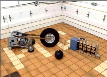
The three standard impact sources used in this study can be seen in Figure 1 below. The ISO tapping machine on the right in the figure has five steel-faced hammers each weighing 0.5 kg. A motor and cam system drives these to strike the floor a total of ten times per second. The drop height is 40 mm. The measured impact sound pressure level (ISPL) is measured in the room below and normalized to account for receiving room conditions, and reference absorption area.
Figure 1: Standard impact sources. From left to right: Tire (bang machine), ball, ISO tapping machine (hammer box). Descriptions of sources can be found in following standards: Tapping machine: ISO 140-7, JIS A 1418-1, KS F 2810-1; heavy impactors: ISO 140-11, JIS
A 1418-2, KS F 2810-2; airborne ISO 140-3.
The two heavy impact sources on the left (tire and ball) were developed by Japanese researchers to deal with the problem of footstep noise, specifically children jumping. Acoustic properties of the ball are described in other studies [8]. The tire and ball are dropped on the floor from 0.85 m and 1 m, respectively. The maximum fast time weighted levels (LF,max) are
measured in the room below. Note, that the metrics used for the heavy impact sources do not normalize data for receive room properties, and that room volume and absorption affect the results [9]. A doubling of room volume decreases the impact levels by 3 dB in all frequency bands, but the absorption normalization is frequency dependent. The Japanese
INTERNOISE 2010 │ JUNE 13-16 │ LISBON │ PORTUGAL
heavy impact single number rating (LH) defined in JIS A 1419-2 considers frequencies between the 63 Hz and 500 Hz octave bands.
2.2 Floor descriptions and variations
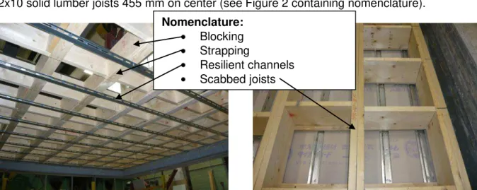
All materials and building practice were typical of Japan. The floors tested were built with 2x10 solid lumber joists 455 mm on center (see Figure 2 containing nomenclature).
Figure 2: Photo’s of assemblies explaining nomenclature and showing base design. The assemblies mentioned in this paper were modified to investigate the effects of stiffening the floor, adding mass, the combination of both, and decoupling the ceiling. The following design changes are considered in this paper:
1. Stiffening perpendicular to the joists through blocking and strapping (B&S) 2. Stiffening parallel to the joists through adding scabbed joists
3. Adding mass through second ceiling layer of gypsum board 4. Stiffening and adding mass through applied topping
5. Decoupling through mounting on resilient channels (RCs)
3 Measured Results
This section presents and discusses the measured results. The first sub-sections each address one of the five design changes listed above, followed by a summary. Several of the parameter changes such as the effects of added stiffness and mass were investigated theoretically for ribbed stiffened plates and found to be very influential, especially in the low frequency range.
The measured impact levels (Li,F,max: ball and tire; TL: airborne, and ISPL: light impactor) are
displayed in third octave bands ranging from 50 Hz to 5000 Hz. In the figures below, which display the effect due to a construction change, a positive number means an acoustical performance improvement.
3.1 Stiffening perpendicular to joists: Blocking and Strapping (B&S)
Blocking and strapping (displayed in Figure 2) stiffen the floor perpendicular to the joists. The results of this design change can be seen in Figure 3 below.
Nomenclature:
Blocking Strapping
Resilient channels Scabbed joists
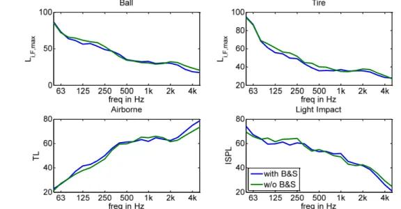
Although both the ball and tire heavy impact sources are supposed to simulate the footfalls of children playing, the Li,F,max values for the tire are approximately 8 dB higher than those of the
ball in the low frequency range. The curve of the tire is steeper than that of the ball, and the levels in the high frequency range are approximately 8 dB lower. The spectrum of the light impact source is quite different than that of either heavy impact source, especially the tire. The coincidence frequency of the gypsum board ceiling can be seen at 2.5 kHz for all sources.
Figure 3: Results for the same floor with and without blocking and strapping (B&S) for ball, tire, airborne, and light impact sources.
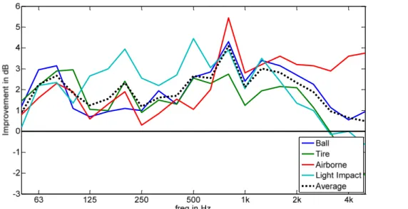
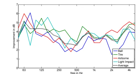
The effect of adding blocking and strapping is difficult to detect on these plots having such large scale, so the level differences (without B&S minus with B&S) for each source are plotted Figure 4. A positive value means a performance improvement due to adding blocking and strapping.
Figure 4: Improvement due to adding blocking and strapping (B&S) for ball, tire, airborne, light impact, and average of all four sources (dashed).
INTERNOISE 2010 │ JUNE 13-16 │ LISBON │ PORTUGAL
The first thing that stands out is that all four sources are affected very similarly by adding blocking and strapping. The average improvement over the sources, marked by a dashed line shows that no one source is an outlier. The improvement due to added blocking and strapping starts above 80 Hz and varies around 3 dB until dropping again (even to negative values) between 315 Hz and 2 kHz. Above 2 kHz the improvement increases to about 3 dB again. The decrease above 4 kHz is due to background noise contamination of the signals which are only around 20 dB. Adding blocking and strapping will improve the performance of the floor for all sources at most frequencies.
3.2 Stiffening parallel to joists: Scabbed Joists
The effect of stiffening the floor parallel to the joists by adding scabbed joists is shown in Figure 5. The data presented in the graph are an average of results from two floors. First was a heavy floor with two layers of 15.5 mm subfloor (already stiff) and two layers of gypsum board ceiling (21 mm + 15 mm); and second was a lighter floor with only one layer of 15.5 mm subfloor and one layer of 12.5 mm ceiling board.
Figure 5: Improvement due to adding scabbed joists for ball, tire, airborne, light impact, and average of all four sources (dashed).
Again results for all the sources are affected similarly by the design change (added scabbed joists) and show an improvement of approximately 2 dB over most of the frequency range. The improvement starts at slightly lower frequencies compared to the addition of blocking and strapping. The light impact source improves slightly more in the mid frequency range than the other sources. Deviations in the upper frequency range are again due to background noise. Stiffening due to adding scabbed joists provides a reasonably frequency independent improvement when compared to blocking and strapping shown in the previous section.
3.3 Adding mass: Ceiling Layer
This section looks at the effect of adding a second layer of 12.5 mm gypsum board to a floor-ceiling assembly on which the base floor-ceiling layer is mounted on resilient channels. The effect of adding resilient channels is discussed in a later section.
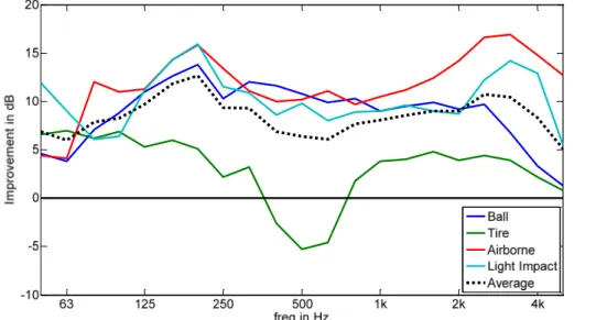
Figure 6: Improvement due to adding second layer of gypsum board to ceiling mounted on resilient channels for ball, tire, airborne, light impact, and average of all four sources.
Here too, all sources show similar improvement due to the design change. The improvement is about 3 dB for all frequencies due to adding a second layer of gypsum board to the resiliently mounted ceiling. This improvement corresponds well with the doubling of the mass rule, and agrees with results observed in a previous floor study [10]. Of the three design changes shown so far, adding an extra ceiling layer gives the largest improvement, especially in the low frequency range.
Less improvement was seen when adding a second layer of gypsum board to a ceiling that was directly attached to the joists. The overall trend and magnitude were similar excluding a series of distinct dips throughout the whole frequency range.
The effect due to adding a second layer of gypsum board depends on the mounting of the first layer. The improvement is greater when the first layer is mounted on resilient channels than when it is directly attached to the floor joists. The average of these two mounting conditions is used in the summary for a comparison of improvements due to design changes.
3.4 Topping
The topping had two layers of gypsum board (21 mm + 15 mm) and a top layer of 15.5 mm plywood. It was placed over a base assembly that was already stiffened parallel to the joists with scabbed joists. The three layers of topping were screwed together, yet the topping itself was not mechanically fastened to the base assembly.
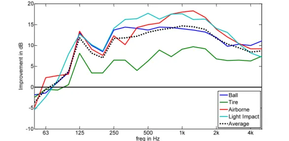
This is the first design change for which the effect was not the same for all sources. Adding this topping gives a similar improvement for all sources except the tire. The average improvement is 6 dB to 10 dB throughout the whole frequency range, when averaged over all sources. Approximately a 4 dB improvement would be expected in the low frequencies due to a change in the total mass from 1250 kg without topping to 2000 kg with topping.
The tire shows much less improvement than the other sources. At 500 Hz adding the topping degraded the performance. This is believed to be caused by non-linearities due to the
INTERNOISE 2010 │ JUNE 13-16 │ LISBON │ PORTUGAL
extremely large peak force of approximately 4000 N and the fastening of the topping to the subfloor. The single layers of the topping were screwed together, however the whole topping was simply placed on the subfloor.
Due to the large impact force of the tire it is possible that the topping might have lifted up slightly, causing an air gap between topping and subfloor. This air gap introduces a spring below the mass of the topping. Assuming the stiffened subfloor can be considered rigged, a gap of 0.4 mm would be sufficient to give a resonance frequency of 500 Hz.
Figure 7: Improvement due to adding a gypsum-plywood topping for ball, tire, airborne, light impact, and average of all four sources.
The reason the resonance is so wide, could be due to the combination of high damping and that air gap has different depths both in time and space. In time, because the topping lifts and drops, and in space, because the topping does not lift as a whole, but locally, getting less the further from the impact location. This non-linear behavior of the system with topping was not observed when the same topping was mechanically attached to the subfloor with screws.
This topping provides a large improvement at low frequencies – considerably greater than was observed for stiffening the floor, or doubling the number of ceiling layers.
3.5 Resilient channels
In this section the change due to adding resilient channels (see Figure 8) is investigated. The resilient channels were applied to a floor that was not stiffened, and had only a single layer of 15.5 mm plywood subfloor, and one layer of 12.5 mm gypsum board on the ceiling.
There are two important things to note. First, all sources show a similar trend with a negative improvement at the frequencies below 63 Hz (and large improvement over the rest of the frequency range with the exception of one dip around 160 Hz). Second, adding resilient channels is less effective at controlling impact sound from the tire than the other sources.
The negative improvement below 63 Hz is caused by a resonance introduced by adding the resilient channels. In a previous study [11], a simple mass-spring-system model was presented where the resilient channels are modeled as a spring placed in parallel with the
stiffness of the air cavity. The study showed that the stiffness of many types of resilient channels is comparable to that of an air cavity having a depth of approximately 100 mm.
The overall stiffness in a parallel system of springs is determined by the spring of least stiffness. Since the depth of the floor cavity is 235 mm, and the equivalent stiffness of the resilient channels is that of a 100 mm air cavity, the resilient channel will control the resonance frequency. In this case the resonance lies slightly below 63 Hz and leads to a much higher sound transmission in nearby frequency bands. Above the resonance frequency decoupling begins. For cavities with a very small depth, the stiffness of the air cavity dominates, and adding resilient channels has little influence in the low frequencies. The resonance can be shifted to lower frequencies out of the range of interest adding more mass to the ceiling.
Figure 8: Improvement due to adding resilient channels to light un-stiffened floor, for ball, tire, airborne, light impact, and average of all four sources.
The reason why resilient channels are least effective at controlling heavy impact sound from the tire in the mid and high frequency range can again be linked to non-linear effects. The vibration of the ceiling is so large due to the extremely large impact force that the ceiling deflection is limited by the expansion of the resilient channel (clipping). At the limit an abrupt change in displacement causes a large increase in velocity which squared is proportional to the radiated power. This shifts some of the low frequency energy content to the higher frequencies, limiting the improvement in that range. This hypothesis is supported by the distinct audible rattling of some floors that have resilient channels.
The non-linear effect of resilient channels can be reduced by stiffening the floor and adding mass to the ceiling. Thereby the vibration levels become smaller and clipping does not occur. This is a large benefit of using scabbed joists when designing for the heavy impactors.
3.6 Summary
The influence of all design changes is summarized below. First the non-linear issues of the tire will be reviewed followed by a discussion of the overall improvements.
INTERNOISE 2010 │ JUNE 13-16 │ LISBON │ PORTUGAL
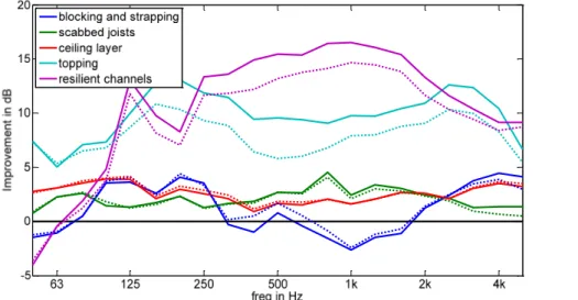
Figure 9 shows the improvements due to all five design changes discussed above. Most of the improvements depicted are averages over several different assemblies. The dashed lines show improvement data averaged over all sources, whereas the solid lines are data averaged over all sources excluding the tire. For changes at which the dashed and solid lines differ strongly, the tire improvements are much less than for the other sources. This is the case for the topping and the resilient channels where the system is driven into non-linear regions by the extreme force of the tire.
All design changes influence the sound transmission of the floor significantly. Some are more effective at high frequencies and some at low frequencies. The ranking at the low frequencies, ranging from 50 Hz to 80 Hz, is of much importance to this project, because there the objective ratings are governed for most wood frame floors. Ranked from least to most effective in this frequency range are: resilient channels tied with blocking and strapping, scabbed joists, added ceiling layer, and finally the plywood-gypsum topping. In the mid frequency range, the ranking shifts to: blocking and strapping, added ceiling layer, scabbed joists, topping and finally resilient channels.
Figure 9: Improvement for all design changes average of all sources (dashed) and all excluding tire (solid).
Only two of the five design changes reduce the effectiveness of the system. Both, adding resilient channels, and blocking and strapping, reduce the performance of the floor in the low frequency range below 80 Hz. The blocking and strapping is also detrimental between 315 Hz and 2 kHz. Stiffening the floor is more effective with scabbed joists. To ensure increased performance resilient channels should be used with a heavy ceiling.
Although at the lower end of the ranking, the scabbed joists are quite important for a good design. First, they show improvement in the low frequency range. Second they tend to reduce non-linear effects which will enhance the performance of RCs, if added.
4 Conclusions and outlook
The results of the paper show that all sources react the same to design changes, except the tire in instances where non-linearities arise. For the linear cases this implies that the change of power injected due to the presented design changes is: 1) the same for all sources or is 2)
not significantly important. The power injected depends on the relation between impedance of source and floor. Due to the design change of the assembly, the floor impedance changes (more or less significantly). In turn this means that the power injected will also change. Being that the impedances of all sources are different, a different change in power injected is expected unless: 1) the impedances of the sources are all similar relative to the floor impedance, or 2) the change in injected power does not play a significant role in the overall change in sound isolation of the assembly. To verify one of the two hypotheses impedance data have been collected on most of the floors tested and will be analyzed.
Either way, by having results from multiple sources that are affected similarly the data set for each design change has grown and guarantees a better accuracy in predictions. This data also will be used to interpolate sound transmission estimates for intermediate floors that were not measured.
The paper also shows that toppings, additional layers of gypsum board on the ceiling, and scabbed joist improve the sound insulation in the low frequency range best.
The support of the Council of Forrest Industries through the Canada Wood and Forestry Innovation Initiative Programs is gratefully acknowledged.
References
1 Zeitler, B.; Nightingale, T.R.T. Impedances of standard impact sources and their effect on impact sound pressure level of floors, Proceedings Acoustics08.
2 Zeitler, B.; Nightingale, T.R.T; Schoenwald, S. Effect of floor treatments on direct impact sound pressure level, Proceedings of Euronoise 2009, Edinburgh 2009.
3 Zeitler, B.; Nightingale, T.R.T; Schoenwald, S. Cremer’s parallel plates applied to lightweight construction, Proceedings of Inter-Noise 2009, Ottawa 2009.
4 Zeitler, B.; Nightingale, T.R.T; Schoenwald, S. A hierarchy of flanking transmission paths in light-weight wood frame construction, Proceedings of Inter-Noise 2009, Ottawa 2009.
5 Nightingale, T.R.T; Bosmans, I. Two modelling approaches for periodic rib-stiffened plates typical of floor assemblies, Proceedings of 14th International Congress on Sound and Vibration, Cairns Australia, July 2007, paper number 488.
6 Zeitler, B.; Nightingale, T.R.T., Methods to control low frequency impact noise in wood-frame construction, Proceedings of Acoustics’08.
7 Halliwell, R.E.; Quirt, J.D.; Warnock, A.C.C. Design and Commissioning of a New Floor Sound Transmission Facility, Proc INCE 93, p995.
8 Schoenwald, S.; Zeitler, B. Nightingale, T.R.T. Excitation of wood joist floors with the standard rubber ball, Proceedings of Inter-Noise 2009, Ottawa 2009.
9 Schoenwald, S.; Zeitler, B. Nightingale, T.R.T. Influence of receive room properties on impact sound pressure level measured with heavy impact sources, Proceedings of International Congress on Sound and Vibration, Cairo 2010.
10 Warnock, A.C.C.; Birta, J.A. Detailed Report for Consortium on Fire Resistance and Sound Insulation of Floors: Sound Transmission and Impact Insulation Data in 1/3 Octave Bands, National Research Council Canada, IRC IR-811, 2000
11 Bradley, AJ.L.; Birta, J.A. A simple model of the sound insulation of gypsum board on resilient supports, Noise Control Engineering Journal, v. 49, no.5, 2001