Publisher’s version / Version de l'éditeur:
Vous avez des questions? Nous pouvons vous aider. Pour communiquer directement avec un auteur, consultez la
première page de la revue dans laquelle son article a été publié afin de trouver ses coordonnées. Si vous n’arrivez pas à les repérer, communiquez avec nous à PublicationsArchive-ArchivesPublications@nrc-cnrc.gc.ca.
Questions? Contact the NRC Publications Archive team at
PublicationsArchive-ArchivesPublications@nrc-cnrc.gc.ca. If you wish to email the authors directly, please see the first page of the publication for their contact information.
https://publications-cnrc.canada.ca/fra/droits
L’accès à ce site Web et l’utilisation de son contenu sont assujettis aux conditions présentées dans le site LISEZ CES CONDITIONS ATTENTIVEMENT AVANT D’UTILISER CE SITE WEB.
Proceedings of Forum Acusticum 2005, pp. 1-6, 2005-08-01
READ THESE TERMS AND CONDITIONS CAREFULLY BEFORE USING THIS WEBSITE.
https://nrc-publications.canada.ca/eng/copyright
NRC Publications Archive Record / Notice des Archives des publications du CNRC :
https://nrc-publications.canada.ca/eng/view/object/?id=71a4a43b-e14d-4ac1-9d74-4605b8582e3b https://publications-cnrc.canada.ca/fra/voir/objet/?id=71a4a43b-e14d-4ac1-9d74-4605b8582e3b
NRC Publications Archive
Archives des publications du CNRC
This publication could be one of several versions: author’s original, accepted manuscript or the publisher’s version. / La version de cette publication peut être l’une des suivantes : la version prépublication de l’auteur, la version acceptée du manuscrit ou la version de l’éditeur.
Access and use of this website and the material on it are subject to the Terms and Conditions set forth at
On the importance of the direct field in structure borne transmission in
framed constructions
On the importance of the direct field in structure
borne transmission in framed constructions
Nightingale, T.R.T., Halliwell, R.E., Quirt, J.D.
NRCC-48143
A version of this document is published in / Une version de ce document se trouve dans:
Proceedings of Forum Acusticum 2005, Budapest, Hungary,
Aug. 29-Sept. 2, 2005, pp. 1-6
On the importance of the direct field in structure borne transmission in framed
constructions
T.R.T. Nightingale, R.E. Halliwell, J.D. Quirt
National Research Council Canada, Institute for Research in Construction, Building M-27, Montreal Road, Ottawa, Ontario, K1A 0R6 CANADA e-mail: trevor.nightingale@nrc.ca
This paper reports findings from a recently completed study of sound transmission in wood framed buildings. The paper begins by showing that the impact sound insulation of floor flanking paths is strongly dependent on the distance from the flanking junction and that adding a topping to the floor modifies the sensitivity to source location. Vibration draw-away measures on the exposed floor surface are used to demonstrate the attenuation of structure borne vibration is different in the directions parallel and perpendicular to the joists, and the attenuation with distance can be significantly modified by the presence of a topping. These vibration measures and the change in Flanking-NISPL with source position indicate that diffuse field assumptions are not valid and suggest that some form of a direct field controls the incident structure borne power. It is also shown that vibration draw-away measures (made on the exposed surface of the floor) can be used to accurately predict the change in Flanking-NISPL with source location. These data are used to explain why the effectiveness of floor toppings to control floor-flanking paths is a function of joist orientation.
1 Introduction
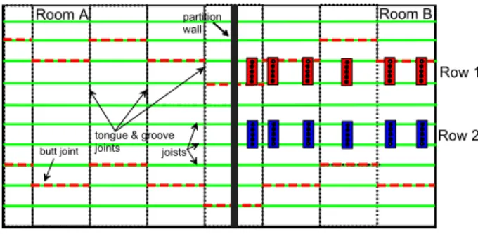
To evaluate structure borne paths involving the floor, measurements were made in rooms A and B of Figure 1. The floor of both rooms was connected at a common wall/floor junction and the oriented strand board (OSB) subfloor was continuous. Measurements were made with the bare floor and with toppings.
A B
C D
Figure 1: Sketch of the floor and the wall separating rooms A and B. The floor had continuous oriented
strand board (OSB). (No scale).
Five toppings were evaluated: 1.) 25 mm thick gypsum concrete floating on an interlayer, 2.) 25 mm thick bonded to the subfloor, 3.) 25 mm thick gypsum fiberboard raft formed from two 12.7 mm thick panels (1.2x2.4 m) glued and screwed together to form a raft that rested on the subfloor but without mechanical attachment, 4.) additional layer of 18 mm of OSB screwed to the existing subfloor, and 5.) simple glue-less laminate flooring floating on an interlayer. Additional information regarding construction details can be found elsewhere [1].
In this paper we use the term propagation attenuation to mean the reduction in structure borne sound power incident on a long junction caused by moving a
localised impact source farther from the junction, (dB/m). The term Flanking-NISPL is defined in ISO 10848-1 and is the normalised sound pressure level due to a specific transmission path from the ISO impact source to the receiver room.
2
Source location and
Flanking-NISPL
Sound pressure levels were measured in room A for different positions of the ISO tapping machine in room B. Figure 2 shows the source locations in room B with six positions on each of two rows ranging from 0.4 m to 3.8 m from the wall/floor junction. The wall separating the two rooms was shielded to suppress flanking paths from the floor to the wall in room A; thus, the sound pressure levels there would be due only to floor-floor transmission.
joists butt joint
tongue & groove joints partition wall Room A Room B Row 1 Row 2
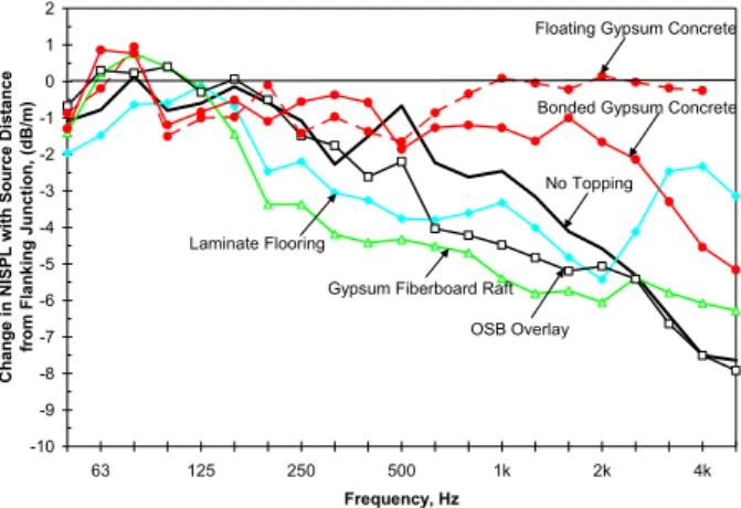
Figure 2: ISO hammer box used to assess the change in Flanking-NISPL with impact source location. Figure 3 shows the average change in Flanking-NISPL as the impact source is moved away from the flanking junction when the floor assembly was bare or had a topping. The most important feature is that with the exception of one case, the floating gypsum concrete,
Forum Acusticum 2005 Budapest Ninghtingale, Halliwell, Quirt
Flanking-NISPL decreases as the ISO tapping machine is moved farther away from the wall/floor junction. Conversely, if the source is moved closer to the junction then the same figure can be used to estimate the increase in Flanking-NISPL. Since the floor appears comparatively homogeneous for propagation parallel to the joists, (i.e., the wavefront does not travel across a series of plate rib junctions), significant reduction of Flanking-NISPL with increasing source distance suggests that the direct field from the source controls the power incident on the junction.
-10 -9 -8 -7 -6 -5 -4 -3 -2 -1 0 1 2 63 125 250 500 1k 2k 4k Frequency, Hz C h ange i n N IS P L wi th S ource D istance
from Flanking Junction, (dB
/m)
No Topping
Laminate Flooring
Gypsum Fiberboard Raft OSB Overlay
Bonded Gypsum Concrete Floating Gypsum Concrete
Figure 3: Average change in Flanking-NISPL in room A for each meter the ISO tapping machine in
room B is moved farther away from the flanking junction.
The effect of source location is strongest at high frequencies where the Flanking-NISPL increases very significantly when the ISO tapping machine is moved closer to the flanking junction. The magnitude is also a function of the floor surface. A topping, or floor surface, that is reasonably homogeneous, isotropic and stiff (e.g., cementitious toppings) will exhibit the least change in Flanking-NISPL with source position.
3
Demonstration of vibration and
structure borne power attenuation
Vibration draw-away data corrected for geometrical spreading (reciprocal of the distance because the dimensions of the source are small compared to the distance and wavelength at most frequencies) provide an estimate of the change in power incident on a very long junction due to moving the source farther away. This enables vibration draw-away curves along a line extending from a localised source to the flanking junction to be used to estimate propagation attenuation – the change structure borne power incident on the junction as the source is moved farther away. Figure 4 shows the location of the point source and the typical positions used to sample the velocity levels indirections parallel and perpendicular to the joists. This was done for the bare floor and a series of toppings.
joists Partition Wall Room A Room B point source measurement locations
Figure 4: Point source and measurement locations used to sample vibration levels as a function of distance. Figure 5 and Figure 6 show the measured propagation attenuation (change in RMS structural velocity per unit distance from the source, dB/m, corrected for geometrical spreading) in the direction parallel to the joists and perpendicular to the joists, respectively. The most important thing to note is that power is attenuated for both directions parallel and perpendicular to the joists and that attenuation increases with increasing frequency for almost all toppings. This means that as the source is moved farther away from the junction less power will reach the junction regardless of the joist orientation, but typically the effect of distance will be greatest when the direction of propagation is perpendicular to the joists.
Relative to the bare floor case, there are two groups of toppings. The first and most desirable are those which generally increase the propagation attenuation, because the power injected by the impact source is attenuated more rapidly with distance, so less power is able to reach the flanking junction. Included in this group is the OSB overlay and the gypsum fiberboard raft. Relative to the bare floor, the OSB overlay exhibits much greater structure borne attenuation perpendicular to the joists.
The bonded and floating gypsum concrete toppings form the second group that offers less propagation attenuation than the bare floor and are the least affected by joist orientation. The bonded and floating gypsum concrete toppings are comparatively homogeneous and isotropic, and reduce the damping and wavenumber of the floor. This makes it easier for the injected power to reach the flanking junction. A very important implication is for topping from this group to be as effective as one from the first group it must offer greater propagation attenuation at the point of impact. This is particularly, true as the distance between the source and the flanking junction is increased.
Relative to the bare floor the toppings rank similarly for both joist orientations – from least propagation attenuation to most: floating gypsum concrete, bonded gypsum concrete, bare floor, OSB overlay, and gypsum
Forum Acusticum 2005 Budapest Ninghtingale, Halliwell, Quirt
fiberboard raft – but that the effect of joist orientation affects some toppings more than others.
-10 -9 -8 -7 -6 -5 -4 -3 -2 -1 0 1 2 63 125 250 500 1k 2k 4k Frequency, Hz Ch an g e i n Stru ctu ral Vel o ci ty wi th Di stan ce co rrected fo r g e o m etri cal sp read in g , (d B/ m)
Floating Gypsum Concrete
Bonded Gypsum Concrete
OSB Overlay No Topping
Gypsum Fiberboard Raft Propagation Direction
Parallel to Joists
Figure 5: Propagation attenuation parallel to the joists obtained from vibration draw-away data.
-10 -9 -8 -7 -6 -5 -4 -3 -2 -1 0 1 2 63 125 250 500 1k 2k 4k Frequency, Hz Ch an g e i n Stru ctu ral Vel o ci ty wi th Di stan ce co rrected fo r g e o m etri cal sp read in g , (d B/
m) Floating Gypsum Concrete
Bonded Gypsum Concrete
OSB Overlay
No Topping
Gypsum Fiberboard Raft Propagation Direction
Perpendicular to Joists
Figure 6: Propagation attenuation perpendicular to the joists obtained from vibration draw-away data. Previously, it has been suggested [3] that the effectiveness of a topping will be a function of joist orientation at the flanking junction. The figures suggest it might be because propagation attenuation in the bare floor is much greater perpendicular to the joists. This is examined in detail in Section 5.
4
Correlation between
Flanking-NISPL and propagation attenuation
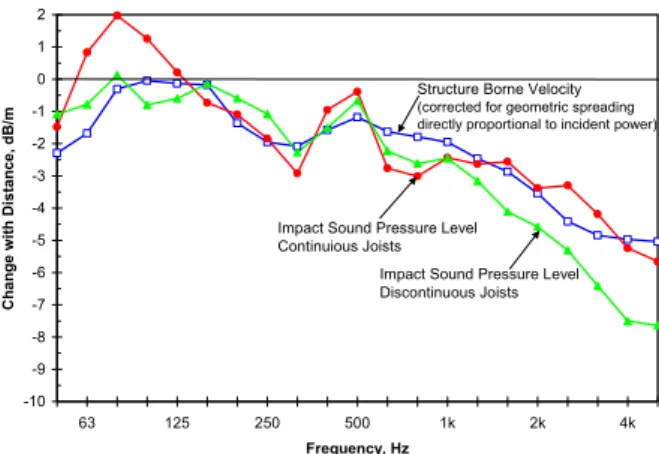
This section compares changes in Flanking-NISPL with source position with estimates of propagation attenuation (obtained from the change in structure borne velocity with distance after correction for geometrical spreading to estimate the power incident on a long junction i.e., Figure 5). Figure 7 shows that the two quantities are highly correlated.With continuous joists, the agreement is typically within one dB over the frequency range where the contours for the single number impact ratings (100 –
3150 Hz) are fitted. The agreement is not so good for the case where the joists are discontinuous. Here the change in Flanking-NISPL is greater than predicted by the change in structure borne velocity, by up to 2 dB in the range 1000-3150 Hz. -10 -9 -8 -7 -6 -5 -4 -3 -2 -1 0 1 2 63 125 250 500 1k 2k 4k Frequency, Hz Ch an g e wi th Di stan ce, d B /m
Structure Borne Velocity (corrected for geometric spreading directly proportional to incident power)
Impact Sound Pressure Level Continuious Joists
Impact Sound Pressure Level Discontinuous Joists
Figure 7: Measured change in Flanking-NISPL with change in impact source distance from the flanking
junction for the bare floor. Also shown is the propagation attenuation with distance from Figure 5. One might expect the case with continuous joists to be slightly less sensitive to source position than with discontinuous joists, if the joists carry more power to, and through, the flanking junction, than does the continuous OSB. It has been shown [2] that the bending wavenumber (reciprocal of wavelength) is much smaller in the joists than the OSB so the OSB will experience much more rapid attenuation with distance. Thus the case with continuous joists should be less sensitive to source position than the one with discontinuous joists. -10 -9 -8 -7 -6 -5 -4 -3 -2 -1 0 1 2 63 125 250 500 1k 2k 4k Frequency, Hz Ch an g e wi th Di stan ce, d B/
m Impact Sound Pressure Level
Structure Borne Velocity (corrected for geometric spreading directly proportional to incident power)
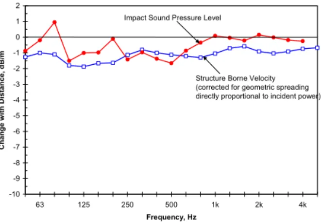
Figure 8: Measured change in Flanking-NISPL with source distance for the gypsum fiberboard topping. Also shown is
the propagation attenuation from Figure 5. Figure 8 shows the excellent agreement between propagation attenuation and the change in Flanking-NISPL with source distance for the gypsum fiberboard raft. The difference is less than 1 dB over the entire frequency range.
Forum Acusticum 2005 Budapest Ninghtingale, Halliwell, Quirt -10 -9 -8 -7 -6 -5 -4 -3 -2 -1 0 1 2 63 125 250 500 1k 2k 4k Frequency, Hz C h a nge w ith D is ta n c e , dB /m
Impact Sound Pressure Level
Structure Borne Velocity (corrected for geometric spreading directly proportional to incident power)
Figure 9: Measured change in Flanking-NISPL with source distance for the floating gypsum concrete topping. Also shown is the propagation attenuation from Figure 5.
5 Estimating effectiveness of
toppings to control flanking
This section identifies factors that should be included in a flanking model for floor transmission paths. These factors are used to estimate changes in Apparent-NISPL due to adding a floating 38 mm thick gypsum-concrete topping. Also the difference in propagation attenuation parallel and perpendicular to a joist is shown to be reason why the effectiveness of a topping to control flanking transmission depends on the orientation of the joists at the flanking junction.
A B
C D
Figure 10: Sketch showing the assembly and the dominant flanking path between rooms B and C for an
impact source on the floor in room B. (No scale). Because the ceiling in room C of Figure 10 is resiliently mounted and the gypsum board of the wall is directly attached, the Apparent-NISPL is controlled by the path from the floor in room B to the partition wall in room C. So the topping does not affect the radiating surface in the receive room, and we can assume that the topping will only affect transmission mechanisms associated with the source room. Figure 11 indicates these are power injected by the source, propagation attenuation and junction attenuation.
Propagation Attenuation Radiation Propagation Attenuation Power Injection Junction Attenuation A B C D
Figure 11: Factors controlling flanking transmission from the floor of room B to the wall in room C. It should be possible to predict the change in the Flanking-NISPL by simply summing the change in dB for each attenuation mechanism. Inspection of Figure 11 suggests, ) atten junct atten (junct ) atten prop atten d(prop ) injected injected ( SPL FlankingNI topping bare topping bare topping bare − + − + Π − Π − = ∆ (1)
where Π is the power injected into the floor by the impact source (dB), d is the distance between the source and the flanking junction (m), prop_atten is the change in draw-away velocity with distance (dB/m) after correction for geometrical spreading of the wavefront, and junct_atten is the structure borne attenuation at the flanking junction (dB).
Note in the limit that there is either no propagation attenuation (because the field is fully diffuse), or the distance between the source and junction is near zero the propagation attenuation term drops out. The remaining terms are what one would expect in a simplified SEA model where the topping did not modify the modal behaviour or damping of the floor (because it acted only locally at the point of impact). In this example we choose the floating gypsum concrete topping because it is least likely to change the mechanics of the junction because it is not bonded to the subfloor. This enables us to assume that the last term relating to junction attenuation can be ignored. It is not easy to obtain an estimate of the injected power by the impact source from measures of the structural response. However, because the Apparent-NISPL was measured in room D, which is directly below the impact source, we will assume that the change in injected power is directly proportional to the change Apparent-NISPL in room D.
The change in the power radiated by the wall in room C will be directly proportional to the sum of the changes in injected power, propagation attenuation, and junction attenuation.
Forum Acusticum 2005 Budapest Ninghtingale, Halliwell, Quirt
Estimates of the third term, relating to the change in propagation attenuation, are given by multiplying the results of Figure 5 and Figure 6 by the distance between the source and flanking junction.
If we know the Flanking-NISPL in room C when the floor in room B is bare (i.e., without a topping), then the Flanking-NISPL in room C after the topping is applied is given by SPL FlankingNI SPL FlankingNI SPL
FlankingNI topping bare
∆ +
= (2)
where the ∆FlankingNISPL is given by Eqn(1). Figure 12 shows the measured Flanking-NISPL for the floor-wall path between rooms B and C when the impact source is 2 m from the flanking junction. Two predictions are also shown in the figure and both use Eqn(2). The first prediction includes the change in propagation attenuation, while in the second it is assumed that the topping does not change propagation attenuation. From the figure it is clear that good agreement between the measured and predicted results is only obtained when propagation attenuation is explicitly considered. Relative to the bare floor, the floating gypsum concrete topping makes it easier for power to reach the flanking junction (as shown by Figure 6). Consequently, failure to properly account for this change in propagation attenuation would result in about a 10 dB underestimation of the Flanking-NISPL over the range 630-4000 Hz.
Similarly, if adding the topping increases the propagation attenuation relative to the bare floor then failure to consider propagation attenuation will result in an overestimation of the Flanking-NISPL.
Floating 38mm Gypsum Concrete Joists parallel to flanking junction
10 20 30 40 50 60 63 125 250 500 1k 2k 4k Frequency, Hz Flanking-N ISPL, dB Measured Predicted propagation attenuation ignored Predicted propagation attenuation included
Figure 12: Measured and predicted Flanking-NISPL between rooms B and C of Figure 10. Eqn(1) has some very important implications. First it indicates the effectiveness of a topping is not derived solely from changing the power injected – propagation attenuation is equally important. Thus, to control flanking transmission it is not necessary to have a massive topping, if the propagation loss (product of distance and propagation attenuation) is large. Second
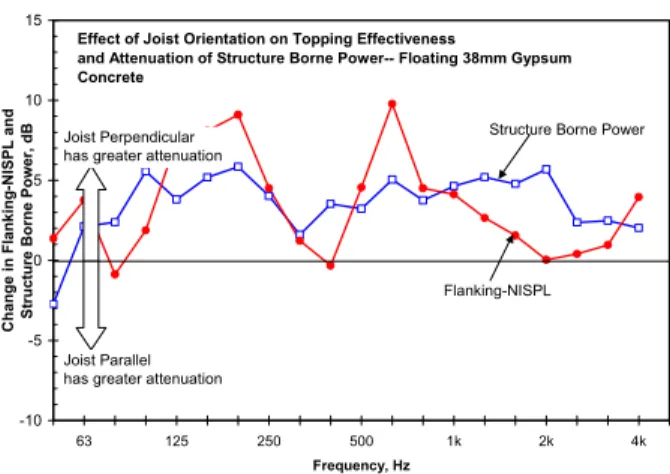
together with Eqn(2), it identifies the source room parameters, and provides a framework, for a simplified impact prediction model for lightweight constructions. Because propagation attenuation depends on direction it is possible Eqn(1) can be used to explain why the effectiveness of floor toppings to control flanking transmission (particularly impact sources) is dependent on the orientation of the joists at the flanking junction. We evaluate Eqn(1) for joists oriented perpendicular (┴) and parallel (||) and take the difference. If it is assumed that the change in injected power due to adding the topping is the same for both joist orientations, then one gets
|| || ) atten prop atten d(prop ) atten prop atten d(prop SPL FlankingNI SPL FlankingNI topping bare topping bare − − − = ∆ − ∆ ⊥ ⊥ (3)
Eqn(3) shows that if effectiveness of a topping depends on the orientation of the joists at the flanking junction, then this can be attributed to differences in propagation attenuation in the directions parallel and perpendicular to the joists. The left hand side of Eqn(3) is obtained directly from measurements of the Flanking-NISPL. The right hand side is the change in incident structure borne power evaluated using the data from Figure 5 and Figure 6 with a source distance of 2 m.
Effect of Joist Orientation on Topping Effectiveness
and Attenuation of Structure Borne Power-- Floating 38mm Gypsum Concrete -10 -5 0 5 10 15 63 125 250 500 1k 2k 4k Frequency, Hz C h ange in Flanking-N ISPL and S tructure B o rne P o wer, dB Flanking-NISPL Structure Borne Power Joist Perpendicular
has greater attenuation
Joist Parallel has greater attenuation
Figure 13: Measured and predicted difference in effectiveness of a floating gypsum concrete topping due
to orientation of the joists at the flanking junction. Figure 13 shows measured (left hand side of Eqn(3)) and predicted using propagation attenuation (right hand side). They both indicate a floating gypsum concrete topping will be more effective when the joists are perpendicular to the flanking junction. While the agreement is not ideal the same trend, and approximately the same magnitude are predicted. This strongly suggests that the dependence of topping effectiveness on joist orientation at the flanking junction can be attributed to the difference in propagation attenuation in the two directions. Eqn(3) also suggests that in general there will be dependence
Forum Acusticum 2005 Budapest Ninghtingale, Halliwell, Quirt
on joist orientation unless the topping has the same propagation as the bare floor.
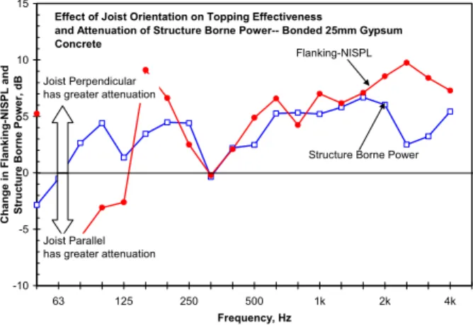
Figure 14 indicates the approach also works for a topping bonded to the subfloor. Agreement between the measured and predicted results shown in Figure 13 and Figure 14 is quite remarkable considering the propagation attenuation was estimated from a single draw away measurement in each direction. Differences at high frequencies are thought to be due to not correcting estimates for the possibility of additional transmission paths involving other surfaces in the receive room or airborne excitation of source room surfaces by self-noise generated by the impact source. Normally, airborne paths are not considered when there is an impact source, but if there is a high rate of structure borne attenuation then airborne paths tend to be more important than when the floor is reverberant.
Effect of Joist Orientation on Topping Effectiveness
and Attenuation of Structure Borne Power-- Bonded 25mm Gypsum Concrete -10 -5 0 5 10 15 63 125 250 500 1k 2k 4k Frequency, Hz C h ange in Flanking-N ISPL and S tructure B o rne P o wer, dB Flanking-NISPL
Structure Borne Power Joist Perpendicular
has greater attenuation
Joist Parallel has greater attenuation
Figure 14: Measured and predicted difference in effectiveness of a bonded gypsum concrete topping due
to orientation of the joists at the flanking junction.
6
Discussion and conclusions
The change in structure borne velocity with distance for a draw-away line on the exposed floor surface can be used to estimate the change in incident structure borne power on a junction as a localised source is moved closer or farther from the junction.
There was good agreement between change in Flanking-NISPL with source distance and estimates of propagation attenuation obtained from the change in velocity with distance after correcting for geometrical spreading of the wavefront. Good agreement was also exhibited when the floor has a topping suggesting that either the exposed floor topping is transmitting the majority of the power to the junction, or that the topping is sufficiently strongly coupled that the rate of power attenuation is the same for both. This should not be interpreted to mean that the topping and the floor below transmit the same power.
The observations in this paper suggest that the vibration energy density of the exposed surface of a joist floor is only reasonably uniform when a comparatively homogenous and massive topping is applied, (25mm or thicker concrete). Otherwise, the vibration field will exhibit a strong gradient that will be different in directions parallel and perpendicular to the joists. So in general, the vibration field will, at best, only very poorly approximate a diffuse field. There are two immediate implications.
Statistical energy analysis (SEA) should not be used as a framework unless there are multiple impact sources that are reasonably uniformly distributed over the whole floor. This condition is unlikely in residential situations because structure borne sources will tend to be localized.
A general model must then address the significant propagation attenuation in the floor, which is a function of direction relative to the joists, and of the floor topping if present. Eqns (1) and (2) provide a framework to predict the improvement due to adding a topping and to predict the Flanking-NISPL with a topping if the bare floor Flanking-NISPL is known. Results for direct transmission of impact sound under laboratory conditions (ISO 140-6) cannot be applied to predict changes in flanking paths when the added topping significantly changes propagation attenuation. If the topping increases propagation attenuation relative to the bare floor then it will be more effective in controlling flanking than direct transmission.
7 Acknowledgements
and
references
This work was supported by a consortium that included Canada Mortgage and Housing, Forintek Canada, Marriott International, Owens Corning, Trus Joist, and USG.
[1] T. R. T. Nightingale, R. E. Halliwell, J. D. Quirt, and F. King, “Transmission at the Wall/Floor Junction in Multifamily Dwellings –
Quantification and Methods of Suppression,” RR-IRC-168 National Research Council, March 2005. [2] T. R. T. Nightingale, R. E. Halliwell, G. Pernica,
“Estimating in-situ material properties of a wood joist floor: Part 1 - Measurements of the real part of bending wavenumber and modulus of
elasticity," Building Acoustics, 11, (3), September, pp. 175-196, 2004
[3] T. R. T. Nightingale, R. E. Halliwell, J. D. Quirt, “Effectiveness of toppings to control flanking transmission in lightweight constructions”, Proceedings of Forum Acusticum, Sevilla 2002, RBA-CIB-009-IP, pp. 1-6.