Publisher’s version / Version de l'éditeur:
Computational Thermal Sciences, 1, 2, pp. 105-120, 2009
READ THESE TERMS AND CONDITIONS CAREFULLY BEFORE USING THIS WEBSITE. https://nrc-publications.canada.ca/eng/copyright
Vous avez des questions? Nous pouvons vous aider. Pour communiquer directement avec un auteur, consultez la première page de la revue dans laquelle son article a été publié afin de trouver ses coordonnées. Si vous n’arrivez Questions? Contact the NRC Publications Archive team at
[email protected]. If you wish to email the authors directly, please see the first page of the publication for their contact information.
This publication could be one of several versions: author’s original, accepted manuscript or the publisher’s version. / La version de cette publication peut être l’une des suivantes : la version prépublication de l’auteur, la version acceptée du manuscrit ou la version de l’éditeur.
For the publisher’s version, please access the DOI link below./ Pour consulter la version de l’éditeur, utilisez le lien DOI ci-dessous.
https://doi.org/10.1615/ComputThermalScien.v1.i2.10
Access and use of this website and the material on it are subject to the Terms and Conditions set forth at
Two-phase flow and mass transfer within the diffusion layer of a
polymer electrolyte membrane fuel cell
Beale, Steven; Schwarz, D. H.; Malin, M. R.; Spalding, D. Brian
https://publications-cnrc.canada.ca/fra/droits
L’accès à ce site Web et l’utilisation de son contenu sont assujettis aux conditions présentées dans le site LISEZ CES CONDITIONS ATTENTIVEMENT AVANT D’UTILISER CE SITE WEB.
NRC Publications Record / Notice d'Archives des publications de CNRC: https://nrc-publications.canada.ca/eng/view/object/?id=5604bdb5-c7de-4143-813f-07311b6ac54a https://publications-cnrc.canada.ca/fra/voir/objet/?id=5604bdb5-c7de-4143-813f-07311b6ac54a
DIFFUSION LAYER OF A POLYMER ELECTROLYTE
MEMBRANE FUEL CELL∗
S. B. Beale,1,†D. H. Schwarz,1 M. R. Malin,2and D. B. Spalding2
1National Research Council, Montreal Road, Ottawa, Ontario, K1A 0R6 Canada; 2Concentration Heat and Momentum Ltd, Bakery House, 40 High Street, Wimbledon
Village London, SW19 5AU Great Britain
The membrane of a polymer electrolyte membrane fuel cell must be hydrated with liquid water at all times in order to function effectively. At high current densities, liquid water in the pores of the diffusion layer inhibits oxygen transport to the cathode. The present paper shows the results of an analysis of two-phase flow and mass transfer in the diffusion layer of a fuel cell. A computational fluid dynamics code is adapted to perform calculations assuming Darcy’s law applies, with the rate of oxygen diffusion governed by Fick’s law. Both relative permeability and capillary pressure are strongly dependent on saturation. A modified version of the interphase slip algorithm is used to perform flow-field calculations. The two phases are each assigned a different pressure. Phase continuity is solved for liquid-phase saturation, from whence capillary pressure, relative permeability, and oxygen exchange coefficients are obtained. Results of numerical calculations are compared to an analytical solution with excellent agreement. Detailed calculations for a typical present-day fuel cells are presented. The results are correlated in terms of gas mass transfer driving force as a function of blowing parameter.
INTRODUCTION
Fuel cells are electrochemical devices that convert chemical energy into electricity and heat. In principle, they are not constrained by the thermodynamic limitations of conven-tional heat engines, and moreover they can employ hydrogen and hydrogen-rich fuels and thus reduce CO2 emissions and global dependence on fossil fuels. Although fuel
cells have yet to achieve the goals of reliability, efficiency, and cost necessary to compete in the marketplace, they are nonetheless the subject of much active research and devel-opment. In order to compete in the future, they must therefore be engineered to a level of performance expectation that exceeds conventional power equipment. Fuel cells are lim-ited by three fundamental factors, namely, charge transfer, ohmic resistance, and mass transfer. The latter predominates at the high current and power densities needed to fur-ther achieve market penetration. The polymer electrolyte membrane fuel cell (PEMFC)
†Correspondence concerning this article should be addressed to S. B. Beale, National Research Council, Montreal Road, Ottawa Ontario K1A 0R6, Canada; e-mail:[email protected].
∗NRC Canada has joint ownership of copyright in this article.
NOMENCLATURE
A cell area, m2 Greek Symbols
b blowing parameter α net drag coefficient
B driving force Γ exchange coefficient, kg/(m·s) g mass transfer coefficient, δ cell half-width, m
kg/(m2·s) ε void space, porosity
g∗ zero-flux mass transfer θ contact angle, deg
coefficient, kg/(m2·s) µ dynamic viscosity, kg/(m·s) H height, m ν kinematic viscosity, m2/s i′′ current density, A/m2 ρ density, kg/m3
J Leverett function σ surface tension, N/m k permeability, /m2 Subscripts
L length, m b bulk
F Faraday’s constant, c capillary
96 485, C/mol ch channel
M molecular weight, dl diffusion layer
kg/mol e electrode (cathode)
m mass fraction eff effective
p pressure, N/m2 g gas
˙
S source term, kg/s H2 hydrogen
˙
S′′ source term, kg/(m2·s) H
2O water
s saturation l liquid
Sh Sherwood number rel relative
T temperature, K O2 oxygen
U superficial velocity, m/s t transformed substance state u phase velocity, m/s P nodal value
x displacement, m 0 ambient, external
is considered to offer potential for mobile applications, and several manufacturers are investing in this technology.
Mass transfer is an interdisciplinary activity, and different approaches abound. In mechanical engineering, the concept of a mass transfer coefficient (Spalding, 1960) is often employed. Conventional fuel cells, such as PEMFCs and solid oxide fuel cells (SOFCs) generally employ gaseous mixtures as reactants and products. Previous work (Beale, 2004) was concerned with single-phase mass transfer and the development of a single-phase SOFC stack model (Beale and Zhubrin, 2005) based on the distributed resistance analogy of Patankar and Spalding (1974). The PEMFC, however, relies on
the membrane being hydrated in order to function effectively, and hence the problem is two-phase—with both liquid and gas present. Lin and Beale (2005) considered transport and electrochemical phenomena in a single commercial PEMFC unit; however, progress in the development of a PEMFC stack model requires extensions of the approach to SOFCs. An important step in the SOFC stack model was the replacement of fine-scale diffusion terms by simple lumped-parameter mass transfer analysis theory. The purpose of the present work, therefore, is to advance previously developed single-phase mass transfer theory so that it can be applied to a two-phase PEMFC. Attention is confined to the cathode-side porous diffusion layer, where liquid water is present. (NB: The term “diffusion layer” enjoys widespread use in the fuel cell literature. However it is something of a misnomer, and is sometimes referred to simply as a “porous transport layer.” We retain the conventional name here while recognizing the shortcomings.)
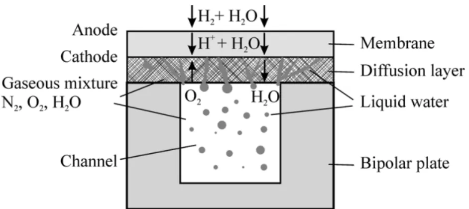
Figure 1 illustrates the problem schematically: hydrogen molecules are oxidized to form protons at the anode and pass through the hydrated membrane to combine with oxygen and form water at the cathode. These are transported via a channel (the main flow is perpendicular to the cross section shown in Fig. 1). The solid bipolar plate houses the channel and serves as an electric current collector for the fuel cell. The porous diffusion layer allows oxygen to pass from the channel to the cathode, and water to move in the opposite direction. The ratio of the channel width to the diffusion layer width is often chosen as 1:2 with the channel and bipolar plate being of equal width. The protons also drag water molecules across the membrane; thus, water is produced at the cathode by two mechanisms: (i) as a product of the electrochemical reaction and (ii) due to electro-osmotic drag. In this study, it is presumed that the gas in the channel is already saturated with water vapor and that all water produced is in the liquid form.
Previous Work
The difficulties associated with conducting physical experiments on PEMFCs have led many researchers to develop mathematical models. Studies have been based on noncou-pled two-phase flow, simplified two-fluid Darcy’s law models, and the so-called “mix-ture” model. However, few correlations exist for two-phase transport properties such as relative permeability and capillary pressure relevant to PEMFC diffusion layers, which restricts the representative accuracy of the models—a notable exception being the work of Gostick et al. (2006).
Bernardi and Verbrugge (1992) give a 1D model in which transport through the cath-ode diffusion layer is governed by Darcy’s law, and liquid and gas flows are assumed to occur in separate pore spaces, i.e., decoupled. Berning et al. (2002) consider a 3D ex-tension of this model. Janssen (2001) presents a model that describes 1D water transport normal to the catalyst layer interface coupled to a 1D along-the-channel mass balance. The model describes two-phase water transport in the diffusion layers using irreversible thermodynamics, and takes into account local equilibrium between the liquid and vapor phases of water at the catalyst layer interfaces.
Nam and Kaviany (2003) present a 1D two-fluid Darcy’s law model for hydrophobic diffusion layers based on water vapor condensation dynamics and capillary motion of the condensate. Pasaogullari and Wang (2004) investigate two-phase transport in both hy-drophobic and hydrophilic diffusion layers. Simplified definitions of two-phase Darcy’s law transport are presented assuming that capillary action is the dominant water trans-port process. The model is further simplified by assuming that there is no liquid water present in the channels and that the gas phase is fully saturated with water vapor. Natara-jan and Nguyen (2001) develop a pseudo-3D, simplified two-fluid Darcy’s law model for the cathode with the discretization of the channel into a series of control volumes that are treated as well mixed. In the diffusion layer, Darcy’s law for liquid water transport is expressed in terms of capillary pressure using Richard’s equation. The vapor and liquid continuity equations are coupled through an interfacial mass transfer rate. The model does not account for momentum effects in the channel.
You and Liu (2002) develop a 2D model for the cathode. When the partial pressure of water vapor exceeds the saturated vapor pressure, liquid water is formed, and the result-ing flow is modeled usresult-ing a mixture model. Meng and Wang (2005) present a 3D model including two-phase transport in the diffusion layers, namely, a liquid coverage model at the channel/diffusion layer interfaces, and a two-phase flow model in the channels. A mixture model is employed to describe gas and liquid water transport in the diffusion layers. In the channels, mist flow is presumed. Mazumder and Cole (2003) develop a comprehensive 3D model to treat the formation and transport of liquid water using a mixture model. Slip between the gas and liquid phases is accounted for by the relative mobility of the two phases, and phase change is modeled. Senn and Poulikakos (2005) consider multicomponent two-phase transport in the diffusion layer, while Innoue et al.
(2006) model mass transfer in the diffusion layer ignoring liquid water transport. Sinha and Wang (2007) study liquid water flooding by means of a pore network model.
Experimental data are few, although Yang et al. (2004) examined two-phase flow in a transparent fuel cell and recorded microscopic optical images of the liquid water. Time-series images show liquid water drops emerging from the diffusion layer and migrating along the walls in an annular fashion. For industrial fuel cells made of graphite plates, the behavior is more likely drop or slug flow, the former growing on and detaching from the diffusion layer. None of the models above devised for diffusion layers can readily describe these channel flow regimes. Conversely, established Eulerian-Eulerian techniques (Spalding, 1980), which are appropriate for describing annular-, drop-, or slug-type flows, need to be modified to consider the two-phase Darcy’s law flow within the porous diffusion layer.
Present Contribution
The primary goal of the present work is to extend previous results for single-phase mass transfer analysis to consider two-phase mass transfer on the air side of a PEMFC. The purpose here is not to develop detailed models specific to any given design, but rather to reduce the two-phase mass transfer problem to a standard form so that fine-scale dif-fusion terms may be replaced by simple rate equations. This will enable the future con-struction of spreadsheet calculation procedures for single PEMFCs as well as CFD-based models for large stacks of cells, where prohibitively expensive fine-grid calculations may be replaced by rate terms (Beale and Zhubrin, 2005). At present, PEMFC stack design is seriously restricted by the inability of the CFD engineer to construct fine meshes within memory limitations and run times typical of present-day computers. A secondary goal of this work is to adapt existing Eulerian-Eulerian methodology to the PEMFC problem so that the deficiencies of the “simplified” models above may be abandoned in favor of more rigorous closure assumptions for future PEMFC models, including channels, diffusion layers, and so forth.
Theoretical Formulation
For fluid flow within the diffusion layer, the incompressible multiphase form of Darcy’s law is presumed to apply as follows:
Ui= siui= −
k µi
krel,igradpi (1)
wherei = l (liquid) or g (gas) as appropriate. In Eq. (1), si is the effective (excluding
connate fluid) phase saturation withsg = 1 − sl, Uiis the filter or superficial velocity, ui
is the phase velocity,k is the absolute permeability, and krelis the relative permeability.
thus accounts for the volume fractions of gas and liquid, but ignores the solid material entirely. The relative permeability of liquid and gas phases are presumed to be
krel,g= s3g (2)
krel,l= s3l (3)
The difference between the gas and liquid pressures is the capillary pressure. This is computed using aJ function (Leverett, 1941) as follows:
pc= pg− pl=
σcos θ
pk/εJ (sl) (4)
Udell (1983) and Pasaogullari and Wang (2004) suggest
J = 1.417 (1 − sl) − 2.120 (1 − sl)2+ 1.263 (1 − sl)3 (5)
J = 1.417sl− 2.120s2l + 1.263s3l (6)
for hydrophilic and hydrophobic media, respectively. Phase continuity, in the absence of phase changes, requires that
div(ρisiui) = 0 (7)
Since gradients of liquid pressure are much larger than those of gas pressure and are equal in magnitude to those in the capillary pressure, Eq. (7) may be conveniently rewrit-ten as a diffusion equation for liquid,
divΓlgradsl= 0 (8) where Γl= √ kεkrel,l νl σcos θdJ dsl (9) For steady-state mass transfer in the gas phase,
div(ρgsgugm) = div sgΓeffgradm (10)
wherem is the mass fraction of any given species. The effective exchange coefficient, Γeff, is estimated using effective medium theory (Nam and Kaviany, 2003),
Γeff = Γε3/2s1/2g (11)
Solution of the system of Eqs. (7)–(10) is obtained in terms of overall continuity (gas pressure correction), phase continuity (saturation), momentum, and scalar transport equa-tions using the interphase slip algorithm (IPSA) (Spalding, 1980) as implemented in the
computer code PHOENICS (Spalding, 2006). This approach differs from previous fuel cell codes in that the two-phase Eulerian-Eulerian system of equations is solved for gas and liquid saturations. It differs from previous IPSA calculations in that the diffusion form of the phase continuity equation, Eq. (8), rather than the convective form, Eq. (7), is solved for the phase saturations. The adopted approach is quite general and may be readily employed in a number of other applications of multiphase flow in porous media. In the PHOENICS code, the phase volume fractions are thus identified as the effective saturations, and the use of “porosities” is thus avoided, although there would be no prob-lem employing these if necessary.
Mass Transfer
Let it be proposed that the diffusive flux in Eq. (10) be replaced by a linear rate term, sgΓeffgradm = sggdl(me− mb) (12)
wheregdlis a diffusion layer mass transfer coefficient,meis the mass fraction of
oxy-gen at the cathodic electrode, andmbis the bulk mass fraction of oxygen at the
chan-nel/diffusion layer interface. The “Ohm’s law” for mass transfer (Spalding, 1960, 1963) may be written as
ρgUg = sggdlB = sgg∗dlb (13)
whereg∗ = g, lim ρU → 0.
B = mb− me me− mt (14) b = ρgUg sggdl∗ (15) The cathode and bulk species mass fractions and phase saturation are not constant and must be obtained by integration over the appropriate surface. Many mass transfer prob-lems involving chemical reactions require thatg is obtained as a function of either the driving force,B, or the blowing parameter, b. Electrochemical devices are rather unique in that the reaction rate, i.e., the mass flux ρgUg, and hence the blowing parameterb,
are prescribed (galvanostatic boundary condition). The fuel cell mass transfer problem is thus characterized by knowledge of the driving forceB as a function of the blowing parameterb. This allows losses due to charge and mass transfer (so-called activation and concentration overpotentials) to be estimated.
Boundary Conditions
The cathode boundary conditions in the transport equations are for fixed flux (Neumann condition) whereas external values are prescribed at the channel boundary as fixed
val-ues or linearized conditions. At the cathode, a constant mass flux corresponding to the current density ofi′′is presumed. The mass sources of oxygen and water are prescribed
according to Faraday’s law as ˙ Sg′′= ρgUg = − MO2i ′′ 4F (16) ˙ Sl′′= ρlUl= (1 + 2α) MH2Oi ′′ 2F (17)
The gas phase mass flux is negative (suction) and the liquid flux is positive (injection). In Eq. (17), the net drag coefficient, α, is the number of water molecules transported from anode to cathode per proton. It includes both the effects of electro-osmotic drag from the anode to the cathode and back diffusion from the cathode to the anode. Thus, the net drag coefficient is much smaller than that due to electro-osmotic drag alone. According to the experimental results of Janssen and Overvelde (2001), α does not depend significantly on the current density at fixed stoichiometry and varies in the range -0.09 to 0.21 for satu-rated gases for Nafion 105 and 112 membranes. At the channel/diffusion layer interface, the external pressure is fixed to a constant value,p0,iwith ˙Si′′= kkrel,i(p0,i− pp,i)/νiδ,
wherepp,iis the in-cell pressure. For the gas, it is assumed thatp0,g= 0; for the liquid,
an interfacial saturations0,lis presumed and used to compute the reference valuep0,lby
means of Eqs. (4) and (6).
At the cathode, chemical species are presumed to emanate from a reservoir at con-stant transferred substance state (Spalding, 1960). Since for the gas phase only oxygen is transferred,mt= 1. The liquid is a pure substance, and no phase change is assumed
to occur, i.e., the gas is fully saturated. The mass transfer of oxygen at the cathode is ˙
S′′
O2 = ρgUg(mt− mP), computed as a fixed source or flux. Mass transfer of oxygen
between the bulk fluid in the channel and the diffusion layer is presumed to be governed by a linear rate equation, ˙S′′
O2 = sggch(mb− mP), where mbis the bulk mass fraction
of oxygen in the channel. The value of the channel mass transfer coefficient, gch, is
obtained from a Sherwood number correlation, with Shch = 5.385 for 1D convection
diffusion (planar channel) and Shch = 2.712 for a square channel with mass transfer at
one boundary only (Shah and London, 1978)
RESULTS
One-Dimensional Two-Phase Mass Transfer
The 1D solution corresponds to the case where the channel and diffusion layer are both planar. An analytical solution is possible for the liquid in the 1D case assumingUg = 0
0.35425¡s4 l − s40,l ¢ − 0.8480¡s5 l − s50,l¢ + 0.6315 ¡s6l − s60,l ¢ − AMH2Oi ′′ 2F µ vl σcos θ√kε ¶ x = 0 (18)
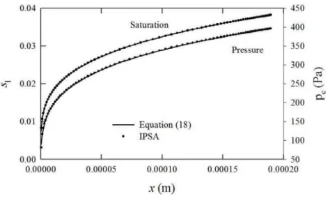
where s0,l is the liquid saturation at x = 0. Figure 2 is a comparison of the results
of calculations performed using the IPSA formulation compared tosl(x) obtained from
Eq. (18) fors0,l = 0. Also shown is the absolute value of the capillary pressure |pc|.
In both cases agreement is near exact, thus validating the IPSA-based methodology for this class of problem. The saturation gradient drives the liquid flow, which is essentially independent of the gas flow. It can be seen thatslandpcare strongly nonlinear near the
origin, where the relative permeability is very small.
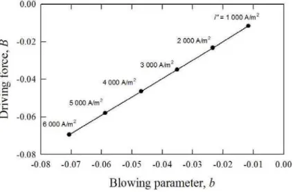
Figure 3 shows the results of the mass transfer analysis for the 1D problem in terms of driving force versus blowing parameter. These are both very small for the fuel cell under consideration, and as is readily apparent from Fig. 3, the graph is linear, with
B = b (19)
This substantially simplifies the PEMFC mass transfer problem. Note however that knowledge of the saturation at the cathode is required in order to computeb in Eq. (15).
Figure 3. Mass transfer driving force versus blowing parameter in 1D.
CFD Results
The results for the case corresponding to the data of Table 1 are shown in Figs. 4–10. These results were obtained with a mesh of40 × 80 computational cells. Figures 4 and 5 show the gas and liquid phase pressures, respectively. The negative relative pressure is indicative of vacuum conditions (with respect to the channel) inside the diffusion layer. It can be seen that the gas pressure field is harmonic (Laplacian) in nature and that the gas and liquid pressure gradients are in opposite directions, since liquid is being injected whereas gas is being removed at the cathode, i.e., the two fluids are in counterflow. Figures 6 and 7 are corresponding pictures of the gas and liquid phase velocities, where the nature of the counterflow for the two phases is readily apparent. Figure 8 shows level lines of the liquid phase saturation, while Fig. 9 illustrates values of the oxygen mass fraction.
The mass transfer driving forceB is shown as a function of the blowing parameter b in Fig. 10. It can be seen that, as was observed in Fig. 3, the driving force versus blowing parameter characteristic is linear. In this case, the saturation used to compute the blowing parameter, Eq. (15), is just the arithmetic mean of the gas saturationsg at
the channel.
DISCUSSION Flow Field Results
Inspection of the results of Figs. 4–7 show that for the gas, there is suction into the dif-fusion layer due to the consumption of gaseous oxygen at the cathode. The gas flow vectors are normal to isobars ofpg, which decrease from the channel to the cathode. The
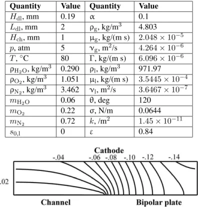
Table 1. Physical details for the particular problem considered
Quantity Value Quantity Value
Hdl, mm 0.19 α 0.1 Ldl, mm 2 ρg, kg/m3 4.803 Hch, mm 1 µg, kg/(m s) 2.048 × 10⁻⁵ p, atm 5 νg, m2/s 4.264 × 10⁻⁶ T ,◦C 80 Γ, kg/(m s) 6.096 × 10⁻⁶ ρH2O, kg/m 3 0.290 ρ l, kg/m3 971.97 ρO2, kg/m 3 1.051 µ l, kg/(m s) 3.5445 × 10⁻⁴ ρN2, kg/m 3 3.462 ν l, m2/s 3.6467 × 10⁻⁷ mH2O 0.06 θ, deg 120 mO2 0.22 σ, N/m 0.0644 mN2 0.72 k, /m 2 1.45 × 10⁻¹¹ s0,l 0 ε 0.84
Figure 4. Gas vacuum pressure (Pa) relative to channel fori′′= 5, 000 A/m2.
Figure 5. Relative liquid pressure (Pa) fori′′= 5, 000 A/m2.
Figure 7. Liquid velocity fori′′= 5, 000 A/m2.
Figure 8. Gas saturation fori′′= 5, 000 A/m2.
Figure 9. Oxygen mass fraction fori′′= 5, 000 A/m2.
converse is true for vectors of the liquid phase where there is injection at the cathode with pldecreasing away from the cathode toward the channel. Thus, the two phases are in
counterflow, with the magnitude of the gradient in the liquid pressure greater than that of the gas, especially near the channel interface. The liquid velocities are smaller in magni-tude than the gas velocities. The water saturation, which is presumed to be very small in the channel, rises substantially within the diffusion layer. The saturation gradient effects a gradient in the capillary pressure, Eqs. (4) and (6), which drives the counterflow of the liquid water in the opposite direction to the gas. Inspection of the liquid saturation, Fig. 8, reveals that the contours are more highly concentrated near the channel boundary, as was shown to be the case in Fig. 2. The boundary value of the liquid saturationslis an
important parameter. When this is small, i.e.,s0,l∼ 0, the saturation gradient driving the
flow near the channel is correspondingly high. However, if the boundary liquid satura-tion becomes too large, the saturasatura-tion and capillary pressure gradients are then too small to permit effective transport through the gas diffusion layer. Thus, if there is sufficient buildup of liquid at the diffusion layer–channel interface, performance will be degraded due to lack of water transport (flooding), i.e., a purely capillary-related effect. This is in addition to any “starvation” effects associated with oxygen being unable to reach the electrolyte due to the presence of liquid water within the pores. Flooding in the channels and/or diffusion layers of PEMFCs is a major concern with negative implications, and it is of much importance that fuel cell scientists develop predictive models to further develop effective and reliable products that do not flood.
Mass Transfer
The fact that the driving force versus blowing parameter graph is linear for a PEMFC of typical contemporary construction is encouraging, and useful for the future construction of simplified-cell or stack-level models. The linear characteristic is due to the fact that the driving force is very small. Since by definition the blowing parameter is the ratio of convection to diffusion, the linear characteristic is a statement to the effect that diffusion is dominant. A corollary is that the mass transfer coefficient,g, is constant, i.e., g = g∗
(for small b). This will allow for a simplified mass transfer methodology to be con-structed, including multiphase effects. A methodology for performing electrochemical and mass transfer calculations for single-phase flow using a spreadsheet-type analysis was described in the appendix of the paper by Beale (2007), and will not be repeated here. The extensions to the present situation are natural and obvious, provided the mean saturation at the diffusion layer–channel interface can be estimated. Knowledge of the driving forceB allows the mass and mole fractions at the cathode to be calculated from the bulk value in the channel, and enables estimates for activation and concentration po-larizations to be obtained. In general, the gas saturation must be less than, but near to, unity since, as has already been discussed, ifsl≫ 0, the PEMFC is not going to function
Numerical Accuracy
It was found that better numerical stability was obtained when the diffusive form of the continuity equation, Eq. (8), as opposed to the convective form, Eq. (7), was solved for the liquid. The reasons for this are not entirely clear; however, this approach is consistent with those of previous workers (Nam and Kaviani, 2003; Pasaogullari and Wang, 2004) and has the advantage of being second-order accurate. In the PHOENICS code, a convective and/or a diffusive formulation may be adopted since the steady-state phase continuity equation is presumed to be of the form,
div(ρs u) = div Γ grad s (20) NB: The origin of the diffusion term in Eq. (20) is in turbulent multiphase flow where a gradient diffusion assumption,−ρs′u′ = Γ grad s, is sometimes presumed. Equation (8)
was conveniently obtained by setting the convection terms in Eq. (20) to be zero, and prescribingΓlaccording to Eq. (9).
A number of assumptions have been made in the construction of the simplified PEMFC diffusion layer—in particular that (i) the local current density at the cathode does not vary significantly and (ii) the liquid saturation at the channel wall is known. The former will only be true at low current densities; however, at high current densities there will be substantial variations ini′′(x). Future studies are required to parameterize
the impact of the current density profile on performance in an appropriate nondimen-sional manner. For the latter, only a detailed analysis of the interfacial phenomena at the channel surface can quantify this important issue.
CONCLUSIONS
The results of this study suggest that it is possible to extend the IPSA (or multiphase SIMPLE) methodology to the analysis of two-phase Darcian flow in PEMFCs. Counter-flow occurs in the diffusion layer of a PEM fuel cell as the result of the production and consumption of liquid water and oxygen gas at the cathode. The motion of the liquid is driven by the capillary pressure, or saturation gradient, and is essentially independent of the gas flow. It is shown that for the reaction rates typical of PEM fuel cells, the mass transfer driving force is small and is a linear function of the blowing parameter. Thus, a standard mass transfer technique (Spalding, 1963) may readily be applied to this particular two-phase flow problem. This will assist in the future development of large-scale two-phase stack simulations based on a distributed resistance analogy, where the construction of CFD grids and solution times are otherwise prohibitively expensive.
The methodology developed here is quite general and thus shows that conventional CFD codes based on standard finite volume techniques may readily be applied to other general-purpose two-phase porous media flows; numerous examples abound in the
nat-ural environment such as groundwater hydrology, petroleum engineering, food process-ing, and many other applications. Situations where both multiphase Darcy’s law and conventional viscous flows (drop, slug, annular, etc.) are simultaneously present are thus amenable to analysis.
REFERENCES
Beale, S. B., Calculation procedure for mass transfer in fuel cells, J. Power Sources, vol. 128, pp. 185–192, 2004.
Beale, S. B., Conjugate mass transfer in gas channels and diffusion layers of fuel cells, ASME J. Fuel Cell Sci. Technol, vol. 4, pp. 1–10, 2007.
Beale, S. B. and Zhubrin, S. V., A distributed resistance analogy for solid oxide fuel cells. Numer. Heat Transfer B, vol. 47, pp. 573–591, 2005.
Bernardi, D. M. and Verbrugge, M. W., A mathematical model of the solid-polymer-electrolyte fuel cell. J. Electrochem. Soc., vol. 139, pp. 2477–2491, 1992.
Berning, T., Lu, D. M., and Djilali, N., Three-dimensional computational analysis of transport phenomena in a PEM fuel cell, J. Power Sources, vol. 106, 284–294, 2002. Gostick, J. T., Fowler, M. W., Ioannidis, M. A., Pritzker, M. D., Volfkovich, Y. M., and Sakars, A., Capillary pressure and hydrophilic porosity in gas diffusion layers for polymer electrolyte fuel cells, J. Power Sources, vol. 156, pp. 375–387, 2006. Innoue, G., Matsukuma, Y., and Minemoto, M., Effect of gas channel depth on current
density distribution of polymer electrolyte fuel cell by numerical analysis including gas flow through gas diffusion layer, J. Power Sources, vol. 157, pp. 136–152, 2006. Janssen, G. J. M., A phenomenological model of water transport in a proton exchange
membrane fuel cell, J. Electrochem. Soc., vol. 148, pp. A1313–A1323, 2001. Janssen, G. J. M. and Overvelde, M. L. J., Water transport in the
proton-exchange-membrane fuel cell: Measurements of the effective drag coefficient, J. Power Sources, vol. 101, pp. 117–125, 2001.
Leverett, M. C., Capillary behavior in porous solids, AIME Trans., vol. 142, pp. 152– 169, 1941.
Lin, Y. and Beale, S. B., Transport phenomena in a proton exchange membrane fuel cell, ASME J. Fuel Cell Sci. Technol, vol. 2, pp. 213–218, 2005.
Mazumder, S. and Cole, J. V., Rigorous 3-D mathematical modelling of PEM fuel cells II. Model predictions with liquid water transport, J. Electrochem. Soc., vol. 150, pp. A1510–A1517, 2003.
Meng, H. and Wang, C. Y., Model of two-phase flow and flood dynamics in polymer electrolyte fuel cells, J. Electrochem. Soc., vol. 152, pp. A1733–A1741, 2005. Nam, J. H. and Kaviany, M., Effective diffusivity and water-saturation distribution in
single- and two-layer PEMFC diffusion medium, Int. J. Heat Mass Transfer, vol. 46, pp. 4595–4611, 2003.
Transient model for the cathode of a proton exchange membrane fuel cell using conventional gas distributors, J. Electrochem. Soc., vol. 148, pp. A1324–A1335, 2001.
Pasaogullari, U. and Wang, C. Y., Liquid water transport in gas diffusion layer of poly-mer electrolyte fuel cells, J. Electrochem. Soc., vol. 151, pp. A399–A406, 2004. Patankar, S. V. and Spalding, D. B., A calculation procedure for the transient and
steady-state behavior of shell-and-tube heat exchangers, In: Afgan, N. and Schl¨under, E. U. (Eds.), Heat Exchangers: Design and Theory Sourcebook, Scripta Book Co., Washington, DC, 1974.
Senn, S. M. and Poulikakos, D., Multiphase transport phenomena in the diffusion zone of a PEM fuel cell, ASME J. Heat Transfer, vol. 127, pp. 1245–1259, 2005.
Shah, R. K. and London, A. L., Laminar flow forced convection in ducts, In: Irvine, T. F.and Hartnett, J. P. (Eds.), Advances in Heat Transfer, Academic Press, New York, 1978.
Sinha, P. K. and Wang, C.-Y., Pore-network modeling of liquid water transport in gas diffusion layer of a polymer electrolyte fuel cell, Electrochim. Acta, vol. 52, pp. 7936–7945, 2007.
Spalding, D. B., A standard formulation of the steady convective mass transfer prob-lem, Int. J. Heat Mass Transfer, vol. 1, pp. 192–207, 1960.
Spalding, D. B., Convective Mass Transfer: An Introduction, Edward Arnold, London, 1963.
Spalding, D. B., Numerical computation of multi-phase flow and heat transfer. In: Tay-lor, C., Morgan, K. (Eds.), Recent Advances in Numerical Methods in Fluids, Piner-idge Press, Swansea, 1980.
Spalding, D. B., PHOENICS overview (Version 3.6). Ludwig, J. C. (Ed.), Report no. TR001, CHAM Ltd., London, 2006.
Udell, K. S., Heat transfer in porous media heated from above with evaporation, con-densation, and capillary effects, ASME J. Heat Transfer, vol. 105, pp. 485–492, 1983.
Yang, X. G., Zhang, F. Y., Lubawy, A. L., and Wang, C. Y., Visualization of liquid water transport in a PEMFC, Electrochem. Solid-State Lett., vol. 7, pp. A408–A411, 2004.
You, L. and Liu, H., A two-phase flow and transport model for the cathode of PEM fuel cells, Int. J. Heat Mass Transfer, vol. 45, pp. 2277–2287, 2002.