Publisher’s version / Version de l'éditeur:
Vous avez des questions? Nous pouvons vous aider. Pour communiquer directement avec un auteur, consultez la
première page de la revue dans laquelle son article a été publié afin de trouver ses coordonnées. Si vous n’arrivez pas à les repérer, communiquez avec nous à PublicationsArchive-ArchivesPublications@nrc-cnrc.gc.ca.
Questions? Contact the NRC Publications Archive team at
PublicationsArchive-ArchivesPublications@nrc-cnrc.gc.ca. If you wish to email the authors directly, please see the first page of the publication for their contact information.
https://publications-cnrc.canada.ca/fra/droits
L’accès à ce site Web et l’utilisation de son contenu sont assujettis aux conditions présentées dans le site LISEZ CES CONDITIONS ATTENTIVEMENT AVANT D’UTILISER CE SITE WEB.
Technical Report (National Research Council of Canada. Institute for Ocean Technology); no. TR-2009-06, 2009-01-01
READ THESE TERMS AND CONDITIONS CAREFULLY BEFORE USING THIS WEBSITE. https://nrc-publications.canada.ca/eng/copyright
NRC Publications Archive Record / Notice des Archives des publications du CNRC : https://nrc-publications.canada.ca/eng/view/object/?id=dbd6856d-b5f0-4342-9f6e-515ef1ffe86e https://publications-cnrc.canada.ca/fra/voir/objet/?id=dbd6856d-b5f0-4342-9f6e-515ef1ffe86e For the publisher’s version, please access the DOI link below./ Pour consulter la version de l’éditeur, utilisez le lien DOI ci-dessous.
https://doi.org/10.4224/18227279
Access and use of this website and the material on it are subject to the Terms and Conditions set forth at Thermal protection in liferafts: assessment of occupant heat balance and development of performance criteria
Mak, L.; Kuczora, A.; Evely, K-A.; Boone, J.; Basset, F.; Ducharme, M.; Brown, R.; Farnworth, B.; Cheung, S.; MacKinnon, S.
TR-2009-06
Technical Report
Thermal Protection in Liferafts: Assessment of Occupant
Heat Balance and Development of Performance Criteria.
Mak, L.; Kuczora, A.; Evely, K-A.; Boone, J.; Basset, F.; Ducharme, M.;
Brown, R.; Farnworth, B.; Cheung, S.; MacKinnon, S.
Mak, L.; Kuczora, A.; Evely, K-A.; Boone, J.; Basset, F.; Ducharme, M.; Brown, R.; Farnworth, B.; Cheung, S.; MacKinnon, S., 2009. Thermal Protection in Liferafts: Assessment of Occupant Heat Balance and Development of Performance Criteria. St. John's, NL : NRC Institute for Ocean Technology. Technical Report, TR-2009-06.
T R - 2 0 0 9 - 0 6
NRC Institute for Ocean Technology
Technical Report
Thermal Protection in Liferafts: Assessment of Occupant Heat Balance
and Development of Performance Criteria
Lawrence Mak, Andrew Kuczora, Kerri-Ann Evely, James Boone, Fabien A. Basset, Michel DuCharme, Rob Brown, Brian Farnworth, Stephen Cheung, Scott MacKinnon
March 2009
Mak, L.; Kuczora, A.; Evely, K-A.; Boone, J.; Basset, F.; Ducharme, M.; Brown, R.; Farnworth, B.; Cheung, S.; MacKinnon, S., 2009. Thermal Protection in Liferafts: Assessment of Occupant Heat Balance and
Development of Performance Criteria. St. John's, NL : NRC Institute for Ocean Technology. Technical Report, TR-2009-06.
The material in this document is covered by the provisions of the Copyright Act, by Canadian laws, policies, regulations and international agreements. Such provisions serve to identify the information source and, in specific instances, to prohibit reproduction of materials without written permission. For more information visit http://laws.justice.gc.ca/en/showtdm/cs/C-42
TR-2009-06 March 2009 REPORT SECURITY CLASSIFICATION
Unclassified
DISTRIBUTION Unlimited TITLE
THERMAL PROTECTION IN LIFERAFTS:
ASSESSMENT OF OCCUPANT HEAT BALANCE AND DEVELOPMENT OF PERFORMANCE CRITERIA
AUTHOR(S)
Lawrence Mak1, Andrew Kuczora1, Kerri-Ann Evely2, James Boone3, Fabien A. Basset2,
Michel DuCharme4, Rob Brown3, Brian Farnworth5, Stephen Cheung6, Scott MacKinnon2
CORPORATE AUTHOR(S)/PERFORMING AGENCY(S)
1National Research Council Canada, 2Memorial University of Newfoundland, 3Offshore
Safety and Survival Center, 4Defence Research and Development Canada, 5Helly Hansen
Canada, 6Brock University
PUBLICATION
SPONSORING AGENCY(S)
Transport Canada, National Search and Rescue Secretariat IOT PROJECT NUMBER
2173
NRC FILE NUMBER KEY WORDS
inflatable life raft, engineering human factors, thermal, protection PAGES xi, 77, App. A-I FIGS. 50 TABLES 11 SUMMARY
Inflatable liferafts are currently used worldwide as a means of evacuation and survival from almost all ocean-going vessels, regardless of their size and purpose. This ranges from fishing and other commercial vessels with small crew sizes to offshore oil installations and passenger ships with thousands of persons onboard. While International Maritime
Organization (IMO) standards currently require inflatable life raft components to “provide insulation” or “be sufficiently insulated”, no performance criteria accompany these requirements (IMO, 1996). This report outlines the methodology and results from an engineering and human factors research project which investigated the gaps in knowledge surrounding inflatable liferaft performance with respect to occupant thermal protection in cold environmental conditions.
The research objectives of this project were to:
1. Develop thermal protection criteria for inflatable life rafts assuming otherwise unprotected occupants.
2. Propose an objective methodology for testing inflatable life raft thermal protection performance.
3. Develop tools for Search and Rescue (SAR) planners to predict survival times of liferaft occupants.
4. Provide guidance to training authorities and manufacturers.
and physical modelling approaches considered over a three-year period to address the project objectives.
The project was undertaken in a multi-phased approach. A phase-by-phase summary of the project findings is provided below, followed by overall project findings and
recommendations.
Phase 1
Phase 1 was designed as a one-week pilot experiment with human subjects, aimed at better understanding the effects and sensitivity of the variables, to observe the rate of occupant heat loss, to validate the proper functioning of equipment and to collect data for preliminary investigation. The primary focus was to assess heat loss from direct contact with the raft floor through conduction. The air temperature and water temperature were 19ºC and 16ºC respectively. Phase 1 results informed the design of Phase 2 and Phase 3 experiments. Phase 1 results summary:
• The effect of wave height is less important with leeway and may be ignored as a first approximation to reduce the number of environmental variables. Heat conductance increases non-linearly with leeway but appears to level off above 0.5 m/s leeway speed. Therefore, waves can be eliminated as an independent variable and leeway speed set to 0.5 m/s for Phases 2 and 3.
• It was observed during an 11-person test that the CO2 concentration inside the
liferaft reached an uncomfortable level (over 5000 ppm) in less than an hour when the canopy was closed and no active ventilation system used.
• The experimental setup was adequate and functional.
Phase 2
Phase 2 was designed to assess occupant heat loss and life raft thermal protection in mild conditions (19ºC air temperature and 16ºC water temperature) based on the findings of Phase 1, using human subjects. Tests were designed to assess floor insulation (inflated or uninflated) and clothing wetness (dry or wet) in four reference test conditions (Phase 2 and again for Phase 3):
1. Inflated raft floor; dry clothing (Idry) 2. Inflated raft floor; wet clothing (Iwet) 3. Uninflated raft floor; dry clothing (Udry)
4. Uninflated raft floor; wet clothing (Uwet)
Phase 2 results summary:
• During exposure in mild conditions inside an enclosed life raft, the wetness of the clothing worn by the occupants and the absence of floor insulation would both significantly decrease the occupant mean skin temperature. However, only the clothing wetness will increase the heat loss from the subjects. (Uwet =
67.4±11.2 W/m2; Iwet = 64.9±11.0 W/m2 compared to Udry = 55.8±8.9 W/m2; Idry =
52.4±5.1 W/m2).
• The thermal stress induced by the different test conditions was not sufficient to significantly and consistently increase the metabolic rate of the occupants through shivering. Despite the mild responses to cold during the exposures (skin
from multiple occupants helped to reduce heat loss. The effect of multiple occupants was further assessed in Phase 3 with colder conditions.
• To maintain CO2 concentration at a safe level during the trials (< 1000 ppm), a
constant flow of fresh air was added to the liferaft. The flow rate of fresh air was 19 l/sec and 38 l/sec for two and six human subjects respectively. Following the analysis of Phase 2 data, it was determined that the ventilation rate produced by the
wind fans alone was sufficient to prevent significant CO2 build-up. As a result, no
active ventilation was used for Phase 3.
• It was necessary to assess if the rectal temperature is a true indicator of the body core temperature when localized cooling is taking place around the buttocks. To this end, a secondary experiment was carried out which confirmed that prolonged lower body surface cooling resulted in a localized cooling effect that compromises the validity of the rectal temperature as a core temperature index. There was no difference in measurement between ear canal and esophageal probes throughout the different phases of the secondary experiment. The use of ear canal probes in the liferaft setting was verified and ear canal probes were added to Phase 3 human subject testing.
• It was determined to be desirable to have test conditions that can induce shivering,
so as to assess if the heat loss can be offset by the heat produced. In addition, longer test duration would help to determine if the body heat storage decreased over time, and to provide the necessary data for the modelling. All of these issues were addressed in Phase 3.
Phase 3
Phase 3 was designed to assess occupant heat loss and life raft thermal protection in cold conditions (5ºC air temperature and 5ºC water temperature). In addition to assessing the liferaft system thermal protection, the data collected was used to develop an occupant heat loss model which interfaced with Cold Exposure Survival Model (CESM) to predict survival time. In Phase 3 testing, both human subjects and a thermal manikin were employed. Phase 3 results summary:
• Manikin measurements of the thermal insulation of a combined system of clothing and liferaft give good agreement with measurements on humans.
• Two repeatability tests conducted demonstrated that the thermal manikin results are
repeatable: 0.177 (m2°C)/W versus 0.171 (m2°C)/W in the Udry reference condition;
and 0.101 (m2°C)/W versus 0.104 (m2°C)/W in the Uwet reference condition.
• Closed cell foam floor insulation provides a comparable level of insulation to that provided by liferafts with an inflatable floor. The Idry reference condition (inflatable
floor) has an insulation value of 0.236 (m2°C)/W compared to 0.221 (m2°C)/W and
0.236 (m2°C)/W for closed cell foam floors provided by two different liferaft
manufacturers.
• A thermal protective aid (TPA) provides considerable additional insulation compared to the tested conditions. The insulation increases most considerably in wet clothing cases (61% and 54% in Iwet and Uwet cases respectively).
• TPA provides more insulation than a wet suit in all cases except Udry.
• For Idry, the best scenario, the insulation obtained by sitting on an inflatable pillow
(0.243 (m2°C)/W) or a lifejacket (0.241 (m2°C)/W) is comparable to sitting directly on
the inflated floor (0.236 (m2°C)/W) or closed cell foam floor (0.236 (m2°C)/W).
• There is a significant decrease in insulation value sitting in 10 cm of water (0.05
(m2°C)/W).
• A special case test comparing one instrumented primary subject in 2-person and 12-person test situations show similar heat loss, indicating that the number of
occupants has limited effect in keeping each other warm under the conditions tested.
Overview
This study addressed the four projects objectives by:
1. Summarizing, in a single graphic, the minimum system insulation required for a survival time or functional time of 36 hours at various temperatures using various raft and personal clothing configurations.
2. Proposing a general method to assess the system thermal insulation, with the liferaft afloat in a pool with turbulent water, typical seating arrangement and realistic
amount of water on the raft floor and in the clothing.
3. Demonstrating that the raft occupant heat loss model developed can be used to generate a set of curves showing the calculated survival and functional times for various scenarios.
4. Confirming the importance for raft occupants to stay dry, to provide insulation in the liferaft floor, to control ventilation rate that is adequate for breathing and still allow liferaft internal temperature to rise, and to provide TPA for everyone.
Conclusions and Recommendations
The main conclusions of the study are:
1. Manikin measurements of the thermal insulation of a combined system of clothing and liferaft give good agreement with measurements on humans, as long as proper corrections for differences between manikin and humans are appropriately applied. 2. System insulation values coupled with a Cold Exposure Survival Model can be
expected to give search and rescue planners reasonable predictions of survival time in liferafts where hypothermia is the main risk factor.
3. Factors which substantially affect the survival time are: a. Wearing of a TPA
b. Clothing wetness
c. Liferaft floor insulation d. Liferaft ventilation rate
The recommendations for liferaft standards or design are: 1. Liferafts should include a TPA for every occupant.
2. Liferafts should include a system to keep the floor dry or enable every occupant to sit above the level of water on the floor.
3. Liferaft floors should be insulated or every occupant should be able to sit on an insulated surface.
4. Liferafts should have a mechanism for controlling ventilation to a level which is adequate for breathing but which will limit the heat loss by convection.
ADDRESS National Research Council Institute for Ocean Technology Arctic Avenue, P. O. Box 12093 St. John's, NL A1B 3T5
THERMAL PROTECTION IN LIFERAFTS:
ASSESSMENT OF OCCUPANT HEAT BALANCE AND
DEVELOPMENT OF PERFORMANCE CRITERIA
TR-2009-06 Lawrence Mak Andrew Kuczora Kerri-Ann Evely James Boone Fabien A. Basset Michel DuCharme Rob Brown Brian Farnworth Stephen Cheung Scott MacKinnon March 2009
Thermal Protection in Liferafts:
Assessment of Occupant Heat Balance and
Development of Performance Criteria
Submitted to
Transport Canada &
The National Search and Rescue Secretariat
March 31, 2009
Mr. Lawrence Mak is the project manager. Lawrence has a B.Eng
(Mechanical Engineering), M.Eng (Ocean Engineering) and a Masters degree in Business Administration. He has 18 years of experimental testing experience involving a variety of offshore structures and marine vessels. He has commissioned the world class Offshore Engineering Basin at NRC and has managed the software development and data analysis portions of NRC testing for external clients such as Hibernia, Terra Nova and entrants in the America’s Cup. In addition to the conduct and analysis of research, Lawrence has significant project management experience.
Mr. Andrew Kuczora is a test data analyst with the research section of
NRC-IOT. He has several years’ prior experience as a Technical Officer within the Open Water Test Facility at NRC-IOT. Before coming to IOT he was solely responsible for the operation of the tow tank facility of the Ocean Engineering Research Centre at Memorial University for 12 years. Previous to that he worked for a number of years at a private sector R&D company in the UK. During the past 3 years he has co-authored 6 technical reports and 9 refereed papers.
Dr. Scott MacKinnon is the Principal researcher. Scott holds Memorial
University’s SafetyNet Research Chair in Workplace Health and Safety. He is an Associate Professor in the School of Human Kinetics and Recreation and holds a cross-appointment with the Faculty of Engineering and Applied Science. He is a member of several national and international working groups and has obtained research funding from provincial, national and international agencies. His PhD was earned from the University of Cape Town in the field of Biomedical Engineering.
School of Human Kinetics and
Recreation
Dr. Fabien Basset currently serves as an assistant professor in the School
of Human Kinetics and Recreation. His expertise covers the enhancement of physical performance factors, acute and chronic responses to exercise, and muscle metabolism. Besides his academic activities, Fabien has served as exercise physiologist for the National Sport Centre in Montreal, working on cardio-respiratory responses with exercise in highly trained athletes.
Survival Centre for over 15 years and has been Transport Canada approved to deliver Marine Emergency Duties training since 1986. Jim has participated in the development and delivery of training to more than four thousand marine and offshore personnel and he has been a lead instructor in the training of coxswains to operate survival craft for the Hibernia and Terra Nova offshore installations. He has been involved in the procuring, commissioning, performance testing and maintenance of survival craft from various manufacturers. In addition, he has participated in the design, prototype development, standards making and approval testing for survival craft and other cold-water survival equipment and is a voting member of the CGSB Committee on Immersion Suits. Jim has many hundreds of hours experience working with liferafts in both training and open ocean environments.
Offshore Safety & Survival Centre
Mr. Rob Brown is the research lead for the Offshore Safety and Survival
Centre. He has a B.Eng and M.Eng (Ocean and Naval Architectural) and is a registered professional engineer. Rob has considerable experience in the conduct of full-scale, field based research, including the study of human performance during mustering and evacuation from passenger ships and rescue of survivors from the ocean. Rob has published about 15 technical papers and has authored/coauthored more than 40 technical client reports.
Dr. Michel DuCharme is a senior defence scientist at Defence R&D
Canada and an Adjunct Professor at both the University of Toronto and the University of Ottawa. He received his PhD from the University of Toronto in 1990 and for the past 23 years, his research has focused on the thermal performance, protection, and survival in extreme environments. Michel has conducted numerous research projects at sea and in the Arctic with the military. He has authored over 120 peer-reviewed publications and about 200 scientific presentations in the field of thermal physiology/protection and survival. He received national and international awards in recognition of his research and was recently the co-recipient of two awards for his work on the revision of the Wind Chill Index which was implemented across North America in 2001.
the transport of heat and moisture from the human body through protective clothing. During his 30 year career, he has worked in the R&D departments of National Defence in Canada and the Netherlands, and with five private sector companies that make protective clothing for cold, wet, immersive, ballistic and chemical-biological hazards. He currently works for both Helly-Hansen Canada Ltd and NanoPore Inc. Helly-Hansen Canada manufactures cold and wet weather clothing as well as flotation and cold water immersion protective garments. NanoPore develops and manufactures novel insulation products and cooling systems for a wide variety of applications including cooling of personnel wearing ballistic or chemical-biological protection. He is the author of about 20 patents in this area.
Dr. Stephen Cheung is an Associate Professor and Canada Research
Chair in Environmental Ergonomics in the Department of Physical Education & Kinesiology (Brock University), as well as Adjunct Professor with the Faculty of Graduate Studies (Dalhousie University). His primary research focus is on the effects of environmental extremes on human physiology and performance. This includes work on minimizing heat stress while wearing protective clothing, understanding the fundamental architecture of the human thermoregulatory system, manual function in the cold and during survival situations, and the design of microclimate cooling systems. He is a member of the Executive Committee for the International Conference on Environmental Ergonomics, and is funded by NSERC and the Canada Foundation for Innovation. Dr. Cheung holds a Ph.D. in Exercise Science from the University of Toronto, and an Honours Diploma from the International Space University.
Liferaft Thermal Protection Final Report i
SUMMARY
Inflatable liferafts are currently used worldwide as a means of evacuation and survival from almost all ocean-going vessels, regardless of their size and purpose. This ranges from fishing and other commercial vessels with small crew sizes to offshore oil installations and passenger ships with thousands of persons onboard. While International Maritime Organization (IMO) standards currently require inflatable life raft components to “provide insulation” or “be
sufficiently insulated”, no performance criteria accompany these requirements (IMO, 1996). This report outlines the methodology and results from an engineering and human factors research project which investigated the gaps in knowledge surrounding inflatable liferaft performance with respect to occupant thermal protection in cold environmental conditions.
The research objectives of this project were to:
1. Develop thermal protection criteria for inflatable life rafts assuming otherwise unprotected occupants.
2. Propose an objective methodology for testing inflatable life raft thermal protection performance.
3. Develop tools for Search and Rescue (SAR) planners to predict survival times of liferaft occupants.
4. Provide guidance to training authorities and manufacturers.
The research was conducted at the National Research Council’s Institute for Ocean Technology in St. John’s, Newfoundland and Labrador, Canada. This world-class facility allowed an
interdisciplinary team of researchers to systematically examine the environmental, human and technological factors related to heat exchange within a liferaft-occupant system. This report details experimental protocols, empirical research findings and physical modelling approaches considered over a three-year period to address the project objectives.
The project was undertaken in a multi-phased approach. A phase-by-phase summary of the project findings is provided below, followed by overall project findings and recommendations.
Phase 1
Phase 1 was designed as a one-week pilot experiment with human subjects, aimed at better understanding the effects and sensitivity of the variables, to observe the rate of occupant heat loss, to validate the proper functioning of equipment and to collect data for preliminary investigation. The primary focus was to assess heat loss from direct contact with the raft floor
Liferaft Thermal Protection Final Report ii through conduction. The air temperature and water temperature were 19ºC and 16ºC
respectively. Phase 1 results informed the design of Phase 2 and Phase 3 experiments. Phase 1 results summary:
• The effect of wave height is less important with leeway and may be ignored as a first approximation to reduce the number of environmental variables. Heat conductance increases non-linearly with leeway but appears to level off above 0.5 m/s leeway speed. Therefore, waves can be eliminated as an independent variable and leeway speed set to 0.5 m/s for Phases 2 and 3.
• It was observed during an 11-person test that the CO2 concentration inside the liferaft
reached an uncomfortable level (over 5000 ppm) in less than an hour when the canopy was closed and no active ventilation system used.
• The experimental setup was adequate and functional.
Phase 2
Phase 2 was designed to assess occupant heat loss and life raft thermal protection in mild conditions (19ºC air temperature and 16ºC water temperature) based on the findings of Phase 1, using human subjects. Tests were designed to assess floor insulation (inflated or uninflated) and clothing wetness (dry or wet) in four reference test conditions (Phase 2 and again for Phase 3):
1. Inflated raft floor; dry clothing (Idry) 2. Inflated raft floor; wet clothing (Iwet) 3. Uninflated raft floor; dry clothing (Udry) 4. Uninflated raft floor; wet clothing (Uwet) Phase 2 results summary:
• During exposure in mild conditions inside an enclosed life raft, the wetness of the clothing worn by the occupants and the absence of floor insulation would both
significantly decrease the occupant mean skin temperature. However, only the clothing wetness will increase the heat loss from the subjects. (Uwet = 67.4±11.2 W/m2
; Iwet = 64.9±11.0 W/m2 compared to Udry = 55.8±8.9 W/m2; Idry = 52.4±5.1 W/m2
). • The thermal stress induced by the different test conditions was not sufficient to
significantly and consistently increase the metabolic rate of the occupants through shivering. Despite the mild responses to cold during the exposures (skin temperature above 30°C, heat loss increased by < 15%; no definitive shivering), rectal temperature significantly decreased for all conditions tested by as much as 1.1°C.
Liferaft Thermal Protection Final Report iii • Since there were no noticeable differences in the thermal responses between the
conditions involving 2 versus 6 occupants, it was not apparent that heat generated from multiple occupants helped to reduce heat loss. The effect of multiple occupants was further assessed in Phase 3 with colder conditions.
• To maintain CO2 concentration at a safe level during the trials (< 1000 ppm), a constant
flow of fresh air was added to the liferaft. The flow rate of fresh air was 19 l/sec and 38 l/sec for two and six human subjects respectively. Following the analysis of Phase 2 data, it was determined that the ventilation rate produced by the wind fans alone was sufficient to prevent significant CO2 build-up. As a result, no active ventilation was used
for Phase 3.
• It was necessary to assess if the rectal temperature is a true indicator of the body core temperature when localized cooling is taking place around the buttocks. To this end, a secondary experiment was carried out which confirmed that prolonged lower body surface cooling resulted in a localized cooling effect that compromises the validity of the rectal temperature as a core temperature index. There was no difference in measurement between ear canal and esophageal probes throughout the different phases of the
secondary experiment. The use of ear canal probes in the liferaft setting was verified and ear canal probes were added to Phase 3 human subject testing.
• It was determined to be desirable to have test conditions that can induce shivering, so as to assess if the heat loss can be offset by the heat produced. In addition, longer test duration would help to determine if the body heat storage decreased over time, and to provide the necessary data for the modelling. All of these issues were addressed in Phase 3.
Phase 3
Phase 3 was designed to assess occupant heat loss and life raft thermal protection in cold conditions (5ºC air temperature and 5ºC water temperature). In addition to assessing the liferaft system thermal protection, the data collected was used to develop an occupant heat loss model which interfaced with Cold Exposure Survival Model (CESM) to predict survival time. In Phase 3 testing, both human subjects and a thermal manikin were employed.
Phase 3 results summary:
• Manikin measurements of the thermal insulation of a combined system of clothing and liferaft give good agreement with measurements on humans.
• Two repeatability tests conducted demonstrated that the thermal manikin results are repeatable: 0.177 (m2°C)/W versus 0.171 (m2°C)/W in the Udry reference condition; and 0.101 (m2°C)/W versus 0.104 (m2°C)/W in the Uwet reference condition.
Liferaft Thermal Protection Final Report iv • Closed cell foam floor insulation provides a comparable level of insulation to that
provided by liferafts with an inflatable floor. The Idry reference condition (inflatable floor) has an insulation value of 0.236 (m2°C)/W compared to 0.221 (m2°C)/W and 0.236 (m2°C)/W for closed cell foam floors provided by two different liferaft manufacturers. • A thermal protective aid (TPA) provides considerable additional insulation compared to
the tested conditions. The insulation increases most considerably in wet clothing cases (61% and 54% in Iwet and Uwet cases respectively).
• TPA provides more insulation than a wet suit in all cases except Udry.
• For Idry, the best scenario, the insulation obtained by sitting on an inflatable pillow (0.243 (m2°C)/W) or a lifejacket (0.241 (m2°C)/W) is comparable to sitting directly on the inflated floor (0.236 (m2°C)/W) or closed cell foam floor (0.236 (m2°C)/W). • For Uwet, the worst scenario, the insulation obtained by sitting on a lifejacket (0.149
(m2°C)/W) is less than wearing a TPA (0.158 (m2°C)/W). However, both are better than sitting directly on an uninflated floor (0.104 (m2°C)/W) or a closed cell foam floor (0.129 (m2°C)/W).
• There is a significant decrease in insulation value sitting in 10 cm of water (0.05 (m2°C)/W).
• A special case test comparing one instrumented primary subject in 2-person and 12-person test situations show similar heat loss, indicating that the number of occupants has limited effect in keeping each other warm under the conditions tested.
Overview
This study addressed the four projects objectives by:
1. Summarizing, in a single graphic, the minimum system insulation required for a survival time or functional time of 36 hours at various temperatures using various raft and
personal clothing configurations.
2. Proposing a general method to assess the system thermal insulation, with the liferaft afloat in a pool with turbulent water, typical seating arrangement and realistic amount of water on the raft floor and in the clothing.
3. Demonstrating that the raft occupant heat loss model developed can be used to generate a set of curves showing the calculated survival and functional times for various scenarios. 4. Confirming the importance for raft occupants to stay dry, to provide insulation in the
liferaft floor, to control ventilation rate that is adequate for breathing and still allow liferaft internal temperature to rise, and to provide TPA for everyone.
Conclusions and Recommendations
Liferaft Thermal Protection Final Report v 1. Manikin measurements of the thermal insulation of a combined system of clothing and
liferaft give good agreement with measurements on humans, as long as proper corrections for differences between manikin and humans are appropriately applied.
2. System insulation values coupled with a Cold Exposure Survival Model can be expected to give search and rescue planners reasonable predictions of survival time in liferafts where hypothermia is the main risk factor.
3. Factors which substantially affect the survival time are: a. Wearing of a TPA
b. Clothing wetness c. Liferaft floor insulation d. Liferaft ventilation rate
The recommendations for liferaft standards or design are: 1. Liferafts should include a TPA for every occupant.
2. Liferafts should include a system to keep the floor dry or enable every occupant to sit above the level of water on the floor.
3. Liferaft floors should be insulated or every occupant should be able to sit on an insulated surface.
4. Liferafts should have a mechanism for controlling ventilation to a level which is adequate for breathing but which will limit the heat loss by convection.
Liferaft Thermal Protection Final Report vi TABLE OF CONTENTS 1 Introduction... 1 2 Objectives ... 2 3 Methodology ... 2 3.1 Design of Experiment ... 2 3.2 Phase 1 Testing ... 3 3.2.1 Overview... 3
3.2.2 Facility and Equipment ... 4
3.2.3 Results... 17
3.3 Phase 2 Testing ... 17
3.3.1 Overview... 17
3.3.2 Facility and Equipment ... 17
3.3.3 Results... 17
3.4 Phase 3 Testing ... 18
3.4.1 Overview... 18
3.4.2 Facility and Equipment ... 19
3.5 Human Testing... 20
3.5.1 Clothing Ensemble and SOLAS Lifejacket ... 21
3.5.2 Subject Positioning ... 21
3.5.3 Anthropometric Measurements... 22
3.5.4 Rectal, Ear Canal and Mean Body Temperature ... 24
3.5.5 Skin Temperature and Heat Flow ... 25
3.5.6 Metabolic Rate ... 27
3.5.7 Thermal Comfort Level ... 28
3.5.8 Postures and Movements within the Liferaft ... 28
3.6 Human Subject Testing Protocol ... 29
3.6.1 Familiarization Trial ... 29 3.6.2 Familiarization Set up ... 29 3.6.3 Familiarization Protocol... 30 3.6.4 Experimental Trials... 30 3.6.5 Subject Preparation ... 31 3.6.6 Data Collection ... 31 3.6.7 Re-warming... 33
3.7 Human Subject Data Reduction... 33
3.8 Human Subject Testing Statistical Analysis ... 33
3.9 Human Subject Results and Discussion... 34
Liferaft Thermal Protection Final Report vii
3.9.2 Exposure Duration ... 35
3.9.3 Mean Skin Temperature and Heat Flow ... 35
3.9.4 Rectal and Ear Canal Temperatures... 37
3.9.5 Mean Body Temperature ... 38
3.9.6 Heat Production ... 39
3.9.7 Thermal Comfort Level ... 39
3.10 Manikin Testing ... 40 3.10.1 Thermal Manikin ... 40 3.10.2 Experimental Setup... 44 3.10.3 Clothing Ensemble... 44 3.10.4 Sitting Posture... 45 3.10.5 Test Program... 46 3.10.6 Data Analysis ... 49
3.10.7 Manikin Results and Discussion... 52
4 Modelling ... 54
4.1 Thermal Protection Criteria ... 54
4.2 Modelling the Impact of Raft and Clothing Properties on Survival Time... 55
4.2.1 Introduction... 55
4.2.2 Overview of CESM... 56
4.2.3 Model of Effective Clothing and Liferaft Insulation ... 56
4.2.4 Comparison of Model Predictions with Human Subject Experiments ... 60
4.2.5 Prediction of survival times for various cases ... 63
4.2.6 Computer Implementation ... 64
5 Discussion ... 65
5.1 Thermal Protection Criteria ... 65
5.2 Testing Methodology to Assess Liferaft Thermal Protection... 67
5.3 Tools for SAR Planners ... 69
5.4 Guidance on Training ... 71
5.4.1 Overview... 71
5.4.2 Current Training Standards... 71
5.4.3 Analysis of Training Needs ... 72
5.4.4 Identify Training Needs ... 73
5.5 Guidance to Manufacturers... 74
6 Conclusions and Recommendations... 75
7 Acknowledgement... 76
Liferaft Thermal Protection Final Report viii Appendix A – Report on Review of Environmental Data ...A1 Appendix B – Report on Phase 1 Testing ...B1 Appendix C – Report on Phase 2 Testing ...C1 Appendix D – Report on Phase 3 Testing ...D1 Appendix E – Video Camera and Digital Video Recorder Specifications ... E1 Appendix F – Heat and Mass Flow Equations... F1 Appendix G – Report on Localised Cooling Experiment ...G1 Appendix H – Validation of Skin Heat Loss Measurements using Heat Flow Transducers... F1 Appendix I – Dissemination Activity ...G1
Liferaft Thermal Protection Final Report ix
LIST OF FIGURES Figure 1 NRC-IOT tow tank (dimensions in meters)... 4
Figure 2 Liferaft exterior... 5
Figure 3 Air and water temperate sensor locations ... 9
Figure 4 Wind sensor locations ... 9
Figure 5 Heat flow sensor locations on the liferaft floor ... 10
Figure 6 Heat flow sensor locations on the flotation chambers ... 10
Figure 7 Heat flow sensor locations on the canopy... 11
Figure 8 Heat flow sensor mounted on raft floor using water-soluble heat sink compound .. 11
Figure 9 Carbon dioxide sensor and raft instrumentation box ... 12
Figure 10 Wind sensor ... 12
Figure 11 Air temperature sensors inside a fibreglass tube... 13
Figure 12 Raft floor inflation system ... 13
Figure 13 Human subject instrumentation boxes ... 14
Figure 14 Raft sensor instrumentation boxes ... 14
Figure 15 Instrumentation on the carriage ... 15
Figure 16 Infra-Red CCD camera mounted to liferaft canopy arch... 16
Figure 17 Typical field of view from liferaft video camera... 16
Figure 18 Ice Tank dimensions. ... 19
Figure 19 National Research Council Canada, Institute for Ocean Technology Ice Tank ... 20
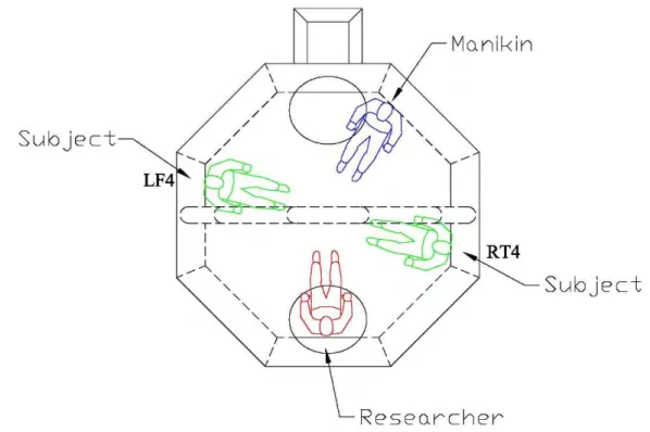
Figure 20 Seating arrangement inside the liferaft. ... 22
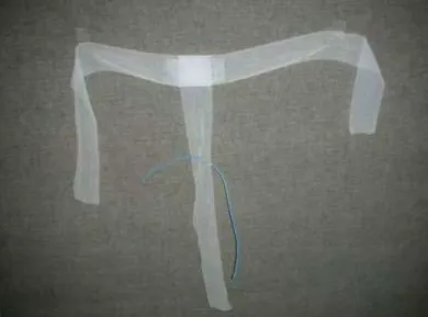
Figure 21 T-bandage and rectal temperature sensor. ... 24
Figure 22 Ear canal temperature sensor. ... 24
Figure 23 Thirteen sites for heat flux transducers... 26
Figure 24 The McGinnis Thermal 13 Point Comfort Scale is a linear scale with written descriptions of thermal comfort (Hollies, 1977)... 28
Figure 25 Familiarization set up... 30
Figure 26 Exposure duration in hours for four conditions tested (Õ denotes significantly different at p<0.05 level). ... 35
Figure 27 Rate of change in Tsk for the four conditions tested (Õ denotes significantly different at p<0.05 level; ÕÕ denotes significantly different at p<0.001 level). ... 36
Figure 28 Mean HF for the four conditions tested (Õ denotes significantly different at p<0.05 level; ÕÕ denotes significantly different at p<0.001 level). ... 36
Figure 29 Rate of change in Tre for the four conditions tested (Õ denotes significantly different at p<0.05 level). ... 37
Liferaft Thermal Protection Final Report x Figure 31 Rate of change in TB for the four conditions tested (Õ denotes significantly different
at p<0.05 level). ... 38
Figure 32 Average MR for the four conditions tested (Õ denotes significantly different at p<0.05 level; ÕÕ denotes significantly different at p<0.001 level). ... 39
Figure 33 Change in thermal comfort level during exposure for four conditions tested (Õ denotes significantly different at p<0.05 level). ... 40
Figure 34 NEMO 23-zone submersible thermal manikin ... 41
Figure 35 NEMO submersible thermal manikin zones ... 42
Figure 36 Thermal Manikin Block Diagram... 43
Figure 37 Thermal manikin seating position inside liferaft relative to the human subjects. .... 44
Figure 38 Thermal manikin sitting posture inside the liferaft during a test condition... 45
Figure 39 Typical human subject sitting posture inside the liferaft during a test condition. .... 46
Figure 40 Insulated floor sample supplied by manufacturer A. ... 48
Figure 41 Insulated floor sample supplied by manufacturer B. ... 48
Figure 42 Measured values of metabolic rate (Expt MR) and heat loss from the heat flow sensors (Expt Heat Flow) for Phase 3 testing compared to the predictions of CESM (Model MR) ... 60
Figure 43 CESM predictions for rectal temperature (Model Tre) compared to the experimental data (Expt Tre) for Phase 3 ... 61
Figure 44 CESM predictions for skin temperature (Model Tskin) compared to the experimental data for Phase 3 (Expt Tskin)... 62
Figure 45 Sample output from CESM for the wet uninflated condition (Uwet) showing the rectal temperature, skin temperature and metabolic rate over time until rectal
temperature reaches 28°C in the simulation. ... 63
Figure 46 Survival time and functional time for the range of values of system insulation using Phase 3 data. The survival and functional times for system insulation values above 0.16 m2K/W are greater than 36h but the CESM does not provide the values... 64
Figure 47 System thermal insulation required for survival time (ST) or functional time (FT) of 36 h at various ambient temperatures (average of air and water temperatures)
(horizontal lines) for different systems tested on the thermal manikin (vertical bars). A key to the labels is given below. ... 66
Figure 48 Survival time as a function of air and water temperatures... 70
Figure 49 Functional time as a function of air and water temperatures ... 70
Liferaft Thermal Protection Final Report xi
LIST OF TABLES
Table 1 Design of Experiment ... 3
Table 2 Physical characteristics of the eight subjects. ... 21
Table 3 Description of the seven skinfold sites. ... 23
Table 4 Comparison of current experiment and Hardy and DuBois’ (1939) weighting factors.27
Table 5 Quantity of water for coverall size... 32
Table 6 Individual subject coverall sizes. ... 32
Table 7 Average baseline measures for four conditions tested on 8 subjects... 34
Table 8 Thermal manikin test matrix... 47
Table 9 Algorithm to adjust for contact area of the thermal manikin with the liferaft. ... 51
Table 10 Manikin overall thermal insulation values... 52
Liferaft Thermal Protection Final Report 1
1 INTRODUCTION
Inflatable liferafts are currently used on almost all passenger, fishing and commercial vessels, and offshore oil installations. Worldwide, liferafts are the primary evacuation system from fishing vessels with relatively small crews to large Roll on/Roll off passenger vessels with over a thousand passengers and crew. While International Maritime Organization (IMO) standards currently require inflatable liferaft components to “provide insulation” or “be sufficiently insulated”, there are no performance criteria for these requirements (IMO, 1996).
In a passenger ship abandonment situation in cold water, passengers may be wearing very little personal protective clothing. Therefore, liferafts provide the only significant thermal protection against the cold ocean environment while they await rescue. Manufacturers equip liferafts with an insulated floor to reduce heat loss from direct contact with the cold ocean water. The
insulation provided is critically important for liferaft occupants who have little protective clothing. The heat loss of unprotected persons is drastically increased if there is a layer of water on the floor as would likely be the case when someone climbs into the liferaft from the ocean or if water is splashed into the liferaft in heavy weather.
In order to address project objectives a series of engineering and human factors trials were undertaken. An overview of the environmental conditions that frame passenger vessel
operations in Canadian waters was carried-out using published historical data (see Appendix A). Following this overview, a three phase experimental approach, over a three-year period,
systematically examined environmental, human and technology factors related to heat exchange within a liferaft-occupant system. Experiments were conducted in mild cold condition in Phases 1 and 2 (16ºC water temperature and 19ºC air temperature), and cold condition in Phase 3 (5ºC water temperature and 5ºC air temperature) to assess the thermal protection of a 16-person, Safety of Life at Sea (SOLAS) approved, commercially available liferaft. Throughout the testing period, opportunities to consider “special cases” arose. In some cases, a thermal manikin
replaced human occupants to assess the validity of such an instrument as a surrogate measure of human performance. This technology will facilitate future research in more extreme conditions that could expose human subjects to unneeded stresses. This manikin also allowed a systematic comparison of commercially available clothing often used as a mechanism for protection against heat loss in evacuation situations.
This report details experimental protocols, empirical research findings and physical modelling approaches considered over a three-year period to address the project objectives. Each phase is documented in technical reports that are found in appendices at the end of this report.
Liferaft Thermal Protection Final Report 2 and professional conferences and in peer-reviewed academic journal. These documents are also included within this report.
2 OBJECTIVES
The research objectives of this project were to:
1. Develop thermal protection criteria for inflatable life rafts assuming otherwise unprotected occupants.
2. Propose an objective methodology for testing inflatable life raft thermal protection performance.
3. Develop tools for Search and Rescue (SAR) planners to predict survival times of liferaft occupants.
4. Provide guidance to training authorities and manufacturers.
3 METHODOLOGY 3.1 Design of Experiment
A Phase 1 pilot experiment was conducted to determine which environmental variables had the most effects on heat loss (see Appendix B). Following this, a second phase of testing (Phase 2) was conducted in a mild cold (19oC air temperature and 16oC water temperature) environment to further explore three variables: floor insulation (uninflated (0.2 cm), inflated (15 cm)), clothing wetness (dry, wet), and occupancy level (12.5%, 37.5%) (See Appendix C). Phase 2 experiment identified floor insulation and clothing wetness to have a significant effect on occupant heat loss. These results were used to inform the test protocol for the experiment reported herewith.
Phase 3 experiment (see Appendix D) was conducted to explore the effects of floor insulation and clothing wetness upon human liferaft occupants in a cold (5oC air temperature and 5oC water temperature) environment. The experiment was a 2 x 2 within-subjects factorial design with independent variables being the floor insulation (uninflated or inflated) and clothing wetness (wet or dry) (Table 1). The four conditions, uninflated - wet (Uwet), inflated - wet (Iwet), uninflated - dry (Udry), and inflated - dry (Idry) had system insulation values of 0.116 ± 0.006 (m2·oC)/W, 0.145 ± 0.017 (m2·oC)/W, 0.185 ± 0.022 (m2·oC)/W, and 0.224 ± 0.023 (m2·oC)/W, respectively.
Liferaft Thermal Protection Final Report 3
Table 1 Design of Experiment
Wet Dry Uninflated 1 Uwet 3 Udry Inflated 2 Iwet 4 Idry 3.2 Phase 1 Testing 3.2.1 Overview
Phase 1 of the experimental program was a one-week experiment, aimed to better understand the effects of different environmental, raft and occupant variables, to observe the rate of occupant heat loss, to validate the proper functioning of equipment and to collect data for preliminary investigation. The primary focus in this phase was to assess heat loss from direct contact with the raft floor through conduction. It was not the intent of this phase to assess human physiological effects due to heat loss.
Leeway
Leeway is the motion of the liferaft over water due to the wind. To simulate this, the towing carriage and a service carriage were utilized to continuously tow the liferaft over the water, back and forth the length of the ice tank, at a speed of 0.5 m/s (0.972 knots) for the duration of each test. The effect of wave height is less important with leeway and may be ignored as a first approximation to reduce the number of environmental variables. Heat conductance increases non-linearly with leeway but appears to level off above 0.5 m/s leeway speed.
Ambient temperatures
The ambient air and water temperatures of the testing environment were measured with 400 series thermistors (model ON-401-PP; OMEGA Engineering, inc., Stamford, CT). The air temperature was measured in four locations on the interior and exterior of the liferaft. The water temperature of the ice tank was measured in two locations near the towing carriage,
approximately 1 meter below the waters surface.
Liferaft Thermal Protection Final Report 4 The temperature and heat loss of the liferafts interior floor, canopy, and side chambers were measured using heat flow transducers (HFT) with integrated thermistors (model FR-025-TH44033-F10 and F-002-4-TH44033-F20; Concept Engineering, Old Saybrook, CT).
Wind speed
Four industrial fans were used to produce 5 m·s-1 wind speeds. It was felt that this wind speed would be adequate for reducing the boundary layer on the liferaft. Three Windsonic
anemometers (model 1405-PK-040; Gill Instruments Ltd., Lymington, Hampshire) were used to measure the wind speeds in different locations: outside the liferaft on the windward side, inside the liferaft on the windward side, and inside the liferaft near the subject.
3.2.2 Facility and Equipment
Tow Tank
The Phase 1 experiments were conducted in the tow tank of National Research Council Canada, Institute for Ocean Technology (NRC-IOT). The tow tank is 200 m long, 13 m wide and 7 m deep (see Figure 1). A dual-flap wave maker at one end of the tank was capable of generating regular and irregular unidirectional waves. For regular waves, the maximum wave height possible was 1 m. For irregular waves, the maximum significant wave height possible was 0.5 m. The operating frequencies range from 0.2 Hz to 1.8 Hz. A parabolic beach at the opposite end of the tank absorbed wave energy and reduced wave reflections. The tank was equipped with a towing carriage capable of speeds up to 10 m/s. The tow tank was equipped with a VMS and Windows-based distributed client/server data acquisition system.
Figure 1 NRC-IOT tow tank (dimensions in meters)
Liferaft
A 16 person Safety of Life at Sea (SOLAS) approved inflatable liferaft (DBC Marine Safety Systems, Richmond, BC) was utilized during this study (see Figure 2). The octagonal liferaft had an overall diameter of 3.31 m and height of 1.56 m. The liferaft was constructed of eight
Liferaft Thermal Protection Final Report 5 constructed of two cylindrical chambers stacked for a total vertical height of 0.63 m. The
inflatable floor was constructed of two layers of butyl rubber that were attached at multiple points with round fasteners. When inflated, the floor formed depressions at the points of attachment. The sides and arch were inflated with CO2 and the floor was inflated with air. The fully inflated floor pressure was 0.5 psi, as per manufacturer specified allowable working
pressure upper range limit. The internal pressures of the inflated components were continuously monitored with a Druck 800 series pressure transducer (model PDCR 830) and adjusted for consistency. The two canopy openings were double closures with ties and were closed for the duration of each test.
Figure 2 Liferaft exterior.
Instrumentation
Two data acquisition systems were used, one system was used to acquire signals from the human subjects and the liferaft, and another system was used to acquire signals on the towing carriage. A bundle of cables, overhung in an umbilical cord, was used to carry the human subject and liferaft signals back to the tow carriage. On the carriage, all the signals from both acquisition systems were acquired by GDAC (GEDAP Data Acquisition and Control) client-server acquisition system, developed by National Research Council Canada, Institute for Ocean Technology. Data was acquired at 1 Hz.
The A/D used was an IOTech Inc. Daqbook /2000, which is a 16 bit, 16 channel system with a maximum throughput of 200 KHz. The maximum analog input voltage range is +/- 10 volts dc. In order to accommodate more than 16 channels, 2 IOTech Inc. DBK12 multiplexer cards were used. Each of these multiplexer cards expands the system capacity by 16 channels (for a total of 32). Additional details for the Daqbook /2000 and DBK12 are available at www.IOTech.com.
Liferaft Thermal Protection Final Report 6 The Isolation Amplifiers utilized in the system were to provide a level of safety for the human subjects. Their purpose is to isolate the humans from potential shock hazards associated with having sensors mounted on their bodies which require a power source (dc excitation source) to function. There were 2 different isolation amplifier designs employed for this project. One of the designs is based on an Analog Devices Model AD210AN isolation amplifier module. This module provides isolation up to 1500 Volts RMS and is configured for unity gain for our
application. Additional details are available at www.Analog.com. The second isolation amplifier design is based on the Burr Brown model ISO122UJ isolation amplifier module. It also has an isolation voltage range of 1500 Volts RMS and is a unity gain amplifier. Additional details are available at www.ti.com.
The Instrumentation Box attached to the heat flow and other sensors on the human subject consists of 14 custom built dual channel Analog Devices AD623BN instrumentation amplifiers. Each of the channels on the dual channel board has a dedicated Analog Devices REF 198 voltage reference IC (4.096 volts) which provides power to the AD623 as well as excitation for all of the thermistor temperature sensors (heat flow sensor temperature, rectal core temperature, ear canal core temperature, and esophageal core temperature) used on the human subject. As part of the effort to isolate the human subject from potentially harmful voltages which could develop from instruments powered from the 110 Volt ac mains, it was decided to derive the Instrumentation Box power from a gel cell lead acid battery placed inside the box. Further details regarding the AD623BN and the REF 198 are available at www.Analog.com.
The IOT 16 channel excitation source, amplifier, and filter unit (analog signal conditioner) is a custom unit developed for signal conditioning applications at IOT. Its major component is the Analog Devices model 1B31AN signal conditioning module per channel, which provides adjustable excitation for sensors, as well as amplification via an integrated instrumentation amplifier. The 1B31AN also has an integral 2 pole Butterworth low pass filter which, for the purposes of the MUN local cooling experiment, has been set to 10 Hz. Most of the sensors utilized for this experiment have derived their excitation from the Instrumentation Box which was located on the human subject. Only the Omega air and water temperature sensors have derived their excitation from the IOT 16 channel analog signal conditioner. Additional details regarding the 1B31AN can be found at www.Analog.com.
The model FR-025-TH44033-F6 heat flow sensors which were attached to the human subject are a 1 inch diameter disc manufactured by Concept Engineering. These sensors employ a standard model TH44033 thermistor with 0.1 deg C accuracy as well as a thermopile (a number of thermocouples sandwiched into the same package to give higher sensitivity and higher output voltage). The thermistor requires excitation, which it derives from the REF 198 as mentioned
Liferaft Thermal Protection Final Report 7 above. The heat flow thermopile does not require excitation, but generates a millivolt output voltage based on the temperature difference between the 2 faces of the sensor. This millivolt level output voltage is amplified by the AD623BN instrumentation amplifier prior to being sent over the long cables to the isolation amplifiers and the remaining data acquisition system components. The thermistor output is on the order of 0.3 to 1 Volt dc and requires little amplification from the AD623BN prior to being sent to the isolation amplifiers and the
remaining data acquisition system components. Additional information regarding the model FR-025-TH44033-F6 sensor can be acquired by contacting Ludwig Holtermann at 860-388-5566 or via e-mail at Concepteng@AOL.com.
The Philips model 21090A rectal / esophageal core temperature sensor contains a type 44004 thermistor with 0.1 deg C accuracy and requires excitation. It derives the excitation from a REF 198 voltage reference in the same manner as the heat flow sensor thermistors. Similar to the heat flow sensor thermistors, the 21090A output is on the order of 0.3 volts dc and requires little amplification. Additional information can be found at
www.medical.philips.com/main/products/supplies/products/temperature_probe.
The Mallinckrodt Tyco model 90045 Mon-a-therm ear canal core temperature sensor can contain either a type 44004 or type 44033 thermistor, both of which are 0.1 deg C accuracy and follow the same calibration curves. Excitation and amplification are achieved in the same manner as for the Philips model 21090A sensor. Additional information can be found at the Mallinckrodt website.
The air and water temperature sensors are Omega Engineering Inc. model ON-401-PP-V. They contain a type 44033 thermistor with 0.1 deg C accuracy. These sensors are connected directly to the IOT 16 channel Excitation Source/ Amplifier / Filter unit. Excitation is derived from an adjustable voltage source on the Analog Devices model 1B31AN signal conditioning module which has been set for 4.096 volts dc. Amplification is also achieved via the 1B31AN module. Additional information regarding the ON-401-PP-V can be found at www.omega.ca. Additional information regarding the Analog Devices model 1B31AN can be found at www.analog.com. Instrumentation inside the raft included:
• Five heat flow sensors on the floor (Model F-025-TH44033-F6; Concept Engineering, Old Saybrook, CT);
• Four heat flow sensors on the floatation chambers (Model F-025-TH44033-F6; Concept Engineering, Old Saybrook, CT),
• Four heat flow sensors on the canopy (F-002-4-TH44033-F20; Concept Engineering, Old Saybrook, CT),
Liferaft Thermal Protection Final Report 8 • A carbon dioxide sensor (CN series remote CO2 IR Transmitter 4-20mA, Comspec,
Toronto, ON),
• Two wind sensors (Model 1405-PK-040; Gill Instruments Ltd., Lymington, Hampshire), • Two air temperature sensors (Model ON-401-PP; OMEGA Engineering, inc., Stamford,
CT),
• A floor inflation system and
• Pressure sensors for raft floatation tube and floor.
This raft floor design secures the inflatable floor with button-like fasteners that create depressions (dimples) in the raft floor and allow water to collect. Heat flow sensors were
installed in raft floor areas with depression and without depression. The raft has two independent floatation chambers. Heat flow sensors were installed on both the upper and lower flotation chambers.
One wind sensor was positioned outside the raft (Model 1405-PK-040; Gill Instruments Ltd., Lymington, Hampshire) and two water temperature sensors (Model ON-401-PP; OMEGA Engineering, inc., Stamford, CT) on the carriage. Layouts of the instrumentation are shown in Figure 3 to Figure 7. Detailed information regarding the raft internal and external environment was collected throughout the tests. Figure 8 to Figure 15 show photographs of the different instrumentation.
Liferaft Thermal Protection Final Report 9 Figure 3 Air and water temperate sensor locations
Liferaft Thermal Protection Final Report 10 Figure 5 Heat flow sensor locations on the liferaft floor
Liferaft Thermal Protection Final Report 11
Figure 7 Heat flow sensor locations on the canopy
Liferaft Thermal Protection Final Report 12 Figure 9 Carbon dioxide sensor and raft instrumentation box
Liferaft Thermal Protection Final Report 13 Figure 11 Air temperature sensors inside a fibreglass tube
Liferaft Thermal Protection Final Report 14
Figure 13 Human subject instrumentation boxes
Liferaft Thermal Protection Final Report 15 Figure 15 Instrumentation on the carriage
Video Recording
An external overhead camera viewing the aft of the raft recorded the raft motions. Two cameras were setup inside the liferaft to provide a means of monitoring subject activities and posture during the testing process, as well as for analysis at a later stage. These two internal infra-red, colour CCD cameras (see Figure 16 and Appendix E) were secured to the port and starboard canopy arches inside the liferaft to view the subject sitting in its field of view (Figure 17). The video feed was annotated to allow synchronisation with other acquired data. Throughout the test programme, video was recorded in raw digital format using digital video recorders (DVRs) manufactured by nNovia Inc. (Appendix E). DVRs had a capacity of up to 8h 39min recording time and permitted the research team to store, backup and analyse video using MS Windows-based software and hardware. Recording video in digital format also sped the backup and analysis times by precluding the need to capture video from tape format to files on a computer. All video was archived-up to LTO-3 backup tape and stored securely.
Liferaft Thermal Protection Final Report 16
Figure 16 Infra-Red CCD camera mounted to liferaft canopy arch
Liferaft Thermal Protection Final Report 17 3.2.3 Results
The main conclusions from Phase 1 testing were:
• The effect of wave height is less important with leeway and may be ignored as a first approximation to reduce the number of environmental variables. Heat conductance increases non-linearly with leeway but appears to level off above 0.5 m/s leeway speed. Therefore, waves can be eliminated as an independent variable and leeway speed set to 0.5 m/s for Phases 2 and 3.
• Heat conductance is about the same with floor inflated 50% and 100%.
• It was observed during an 11-person test that the CO2 concentration inside the liferaft
reached an uncomfortable level (over 5000 ppm) in less than an hour when the canopy was closed and no active ventilation system used.
• The experimental setup was adequate and functional.
3.3 Phase 2 Testing
3.3.1 Overview
Informed by the results of Phase 1 testing, the Phase 2 test series (see Appendix C) was undertaken using human subjects. Experiments were conducted in mild cold (16ºC water temperature and 19ºC air temperature) condition to assess the thermal protection of a 16-person liferaft. A series of tests using different floor inflations and clothing wetness were conducted. 3.3.2 Facility and Equipment
Equipment and facilities were similar to those described in Phase 1. A complete description of the facility and equipment is contained in Section 3.2.2.
3.3.3 Results
During exposure to a mild cold environment inside a closed liferaft, the wetness of the clothing worn by the occupants and the absence of floor insulation both significantly decreased the mean skin temperatures of the occupants. However, only the clothing wetness increased the heat loss from the subjects (Wet clothing, Uninflated floor 67.4±11.2 W/m2
; Wet clothing, Inflated floor 64.9±11.0 W/m2 compared to Dry clothing, Uninflated floor 55.8±8.9 W/m2
; Dry clothing, Inflated floor 52.4±5.1 W/m2
Liferaft Thermal Protection Final Report 18 The thermal stress induced by the different test conditions was not sufficient to significantly and consistently increase the metabolic rate of the occupants through shivering. Despite the mild responses to cold during the exposures (mean skin temperature above 30°C, heat flow increased by < 15%; no definitive shivering), rectal temperature significantly decreased for all conditions tested by as much as 1.1°C. This was particularly the case for the dry uninflated floor condition where the mean skin temperature was on average 32°C by the end of the exposure, and both heat flow and metabolic rate had not increased from baseline.
If the observed rate of decrease in rectal temperature for that condition is extrapolated, it could be predicted that the occupants would not survive for more than 18 hours inside a liferaft originally designed for a multi-days survival in much colder environments. It is concluded that to estimate survival time inside a liferaft, or to evaluate the thermal protection of a liferaft, the short-term decrease in rectal temperature from the occupants should not be the only or the primary factor taken into consideration. It is necessary to assess if the rectal temperature is still a true indicator of the core body temperature when localized cooling is taking place around the buttock. A supplementary experiment (refer to Appendix G) confirmed that due to localised cooling, rectal temperature is not a good representation of body core temperature. Body core temperature in this application should be measured by ear canal or esophageal probes.
It is also desirable to have test conditions that could induce shivering, so as to assess if the heat loss can be offset by the heat produced. In addition, longer test duration will help to determine if the body heat storage is decreasing over time. These will be addressed in Phase 3.
Since there were no noticeable differences in the thermal responses between the conditions involving 2 versus 6 occupants, it was not apparent that heat generated from multiple occupants helped them to reduce heat loss. The effect of multiple occupants will be further assessed in Phase 3.
3.4 Phase 3 Testing
3.4.1 Overview
The experiments of Phase 3 were designed using results obtained in Phases 1 and 2. This experimental protocol examined the effects of clothing wetness and floor inflation over a significantly longer exposure time compared to the Phase 2 protocol. Subjects were asked to attempt an 8-hour exposure under four repeated measures (wet/dry clothes and
Liferaft Thermal Protection Final Report 19 necessary to simulate more realistic survival conditions and to achieve steady state physiological responses required for the modelling exercise. In most cases, subjects endured the considerable exposure time. The research team also took this opportunity to perform “special case” data collections employing a thermal manikin and different protective clothing ensembles. 3.4.2 Facility and Equipment
Ice Tank
Experimental data were collected in the Ice Tank (see Figure 18) of the National Research Council Canada, Institute for Ocean Technology (NRC-IOT) (St. John’s, Newfoundland and Labrador, Canada).
Figure 18 Ice Tank dimensions.
The ice tank is 90 m long x 12 m wide x 3 m deep. The Ice Tank is equipped with a VMS and Windows based distributed client/server data acquisition system.
The towing carriage was connected to a small service carriage via two aluminum truss-like structures, which allowed the two carriages to move as a unit. The service carriage was
Liferaft Thermal Protection Final Report 20 positioned at the back of the towing carriage. The liferaft was set up between the towing carriage and the service carriage (Figure 19).
Figure 19 National Research Council Canada, Institute for Ocean Technology Ice Tank Two towlines were extended from the fore and aft tow points of the liferaft to two towing posts on the service carriage and the towing carriage respectively. During the experiments, both carriages towed the liferaft (depending on the tow direction) in calm water, up and down the tank, to simulate leeway (speed of liferaft over water). The liferaft was free to surge, sway, heave, yaw, pitch and roll. The electrical cables for the various sensors were overhung using an umbilical cord, so they did not influence the liferaft motion.
The same 16 person liferaft described in Section 3.2.2 was used in the Phase 3 tests. The manufacturer’s tow points were not used. Instead, two new tow points were made at the two entrances. These tow points enabled fans installed on the towing carriage to blow wind directly at the liferaft entrances.
3.5 Human Testing
Eight healthy volunteers with no previous cold related injuries or illnesses gave their informed written consent to participate in this study. Approval for this study was obtained from the Memorial University of Newfoundland, Human Investigation Committee (MUN-HIC) and the National Research Council Canada, Ottawa Research Ethics Board (NRC-OREB). All subjects
Liferaft Thermal Protection Final Report 21 were cleared for participation in this study upon completion of a medical history questionnaire. Subjects were instructed to refrain from consumption of food two hours, caffeine and hot beverages six hours, and exercise and alcohol 24 hours prior to the start of each data collection period. Physical characteristics of the subjects are presented in Table 2.
Table 2 Physical characteristics of the eight subjects.
Subject Age Gender Mass (kg) Height (cm) Body Fat (%) Surface Area (m2) 1 26 M 107.6 188 28.5 2.38 2 35 M 105.6 180 31.2 2.32 3 21 F 82.2 171 32.8 1.99 4 24 M 89.2 185 16.3 2.15 5 26 F 62.8 168 24.6 1.72 6 36 F 57.5 159 20.1 1.61 7 22 M 94.9 174 29.9 2.16 8 20 M 75.8 182 6.1 1.96 Mean 26.3 - 84.4 176 23.7 2.04 SD 6.1 - 18.5 9.7 9.1 0.27
3.5.1 Clothing Ensemble and SOLAS Lifejacket
The subjects wore a full length, non-insulated 100% cotton coverall with zip front closure (model Big Bill 414; Codet inc., Magog, QC), 100% cotton short sleeve t-shirt, 100% cotton briefs, and a SOLAS approved lifejacket (model MD8000; Mustang Survival, Richmond, BC). The extremities were protected against non-freezing cold injuries with wool lined leather
mittens, wool socks and 5mm neoprene boots with zipper (model BT500; XS Scuba, Santa Ana, CA). The clothing was selected to represent a typical clothing insulation worn by passengers during ship abandonment.
3.5.2 Subject Positioning
Subjects sat on opposite sides of the liferaft in RT4 and LF3 positions. A thermal manikin was situated in the RT1 position, and a researcher sat at the exit (see Figure 20). This seating
arrangement minimized or eliminated body heat transfer between occupants and evenly ballasted the liferaft.