BotKit: The Robot Construction Kit
by
Edwin W. Foo
Submitted to the Department of Electrical Engineering and Computer
Science in Partial Fulfillment of the Requirements for the Degree of
Master of Engineering in Electrical Engineering and Computer Science
at the
MASSACHUSETTS INSTITUTE OF TECHNOLOGY
June 1999
©
1999 Edwin W. Foo. All rights reserved.
The author hereby grants to MIT permission to reproduce and
ENG
distribute publicly paper and electronic copies of this thesis document
in whole or in part. MASSACH E
Author... .
...
....
IJ RARJES
De artment of Electrical Engineering and Computer Science
May 21, 1999
Certifiedby..
...
James E. Hicks
Research Staff: Compaq Cambridge Research Laboratory
Thesis Supervisor
Certified by.
John Chapin
Assistant Professor: Laboratory for Computer Science, MIT
Thesis S
e visor
Accepted by... ...--- .
Arthur C. Smith
Chairman, Department Committee on Graduate Students
BotKit: The Robot Construction Kit
by
Edwin W. Foo
Submitted to the Department of Electrical Engineering and Computer Science on May 21, 1999 in Partial Fulfillment of the Requirements for the Degree
of Master of Engineering in Electrical Engineering and Computer Science
Abstract
Embedded systems exhibit reactive behaviors that can rapidly respond to stimuli, yet must keep a long-term goal in sight. These requirements make software development for such systems difficult because of the conflicting short-term and long-term goals. The subsumption architecture attempts to solve this issue by presenting a system in terms of a network of horizontally layered behaviors implemented using Augmented Finite State Machines (AFSMs). The subsumption architecture works well but has not found its way into widespread use; one possible reason is the mindshift required to express behaviors in terms of a state machine. Another barrier is the traditional im-plementation of subsumption architectures in hardware or specialized programming languages. This thesis describes an attempt to address both issues using a subsump-tion architecture implemented in Java as well as an encapsulasubsump-tion system designed to allow fragments of robot behaviors coded using traditional methods that are to be embedded in AFSMs. The approach allows a bottom-up incremental approach to system implementation while encouraging an eventual reimplementation from the top down. This was also introduced to contestants in the 1999 6.270 Autonomous Robot Design Competition with some degree of success.
Thesis Supervisor: James E. Hicks
Title: Research Staff: Compaq Cambridge Research Laboratory Thesis Supervisor: John Chapin
Acknowledgments
Jamey Hicks was my primary advisor and mentor during my work on BotKit and the RoboSkiff controller at the Compaq Cambridge Research Laboratory (CRL) in Cambridge, Massachusetts. He greatly influenced the design and implementation of BotKit, and was project lead for the Skiff controller project at CRL. John Chapin at the MIT Laboratory for Computer Science was my on-campus thesis advisor and also provided guidance in the writing process. CRL supported my research through a graduate fellowship in the MIT VI-A program.
The rest of the engineering and research team at CRL who worked on RoboSkiff also deserves a word of thanks. Without these people, Skiff would have never become gone from a sketch on a piece of paper to a working board in three months. In no particular order, the RoboSkiff team is: Frank Bomba, Geoff Bomba (Frank's son),
Ed Chang, Jack Costanza (MIT AI Lab), Donald Denning, Bob Iannucci (Laboratory Director), Chris Joerg, Jason Lee, Dave Panariti, and Mike Schnexnaydre.
I would also like to acknowledge the 1999 6.270 organizers for their efforts in making the 1999 contest the best one yet. They are: Mike Allen, Rob Blau, Andy Chang, Adrian Danieli, Grant Emery, Anthony Hui, Steve Paik, Gong Ke Shen, and Yonah Schmeidler. Charatpong Chotigavanich, Bruce Po, and Joyance Meechai also deserve special mention for going beyond the call of duty as 6.270 Teaching Assistants and helping with the boards during the contest. All the rest of 6.270 Staff also deserve mention; without them, the contest would never have happened.
The 1999 6.270 contestants deserve special mention for being willing to put up with prototype hardware and software and constructing working robots despite the odds. Everyone should be proud of you for pulling that off.
Last, but certainly not least, I give thanks to God for giving me the energy and peace of mind I needed to finish. Many of my friends at church and fellowship also gave a lot of support and encouragement when it seemed that nothing was working.
This thesis is dedicated to Irene Foo. Thanks for everything, Mom. I hope you get well soon.
Contents
1 Introduction
1.1 Embedded Systems . . . . 1.1.1 Introduction . . . . 1.1.2 Development Cycles . . . . 1.1.3 Real-Time Response/Reactive Control 1.1.4 Code Reliability . . . . 1.2 Robotics and Embedded Software . . . . 1.3 Motivation: The MIT 6.270 Contest . . . . 1.3.1 Author's involvement . . . . 1.3.2 Original 6.270 Controller History . . . 1.3.3 Compaq CRL Involvement . . . . 1.3.4 Development Software . . . . 1.3.5 Final Software Specifications . . . . 1.4 Robot Controller Hardware/OS Requirements
1.4.1 Hardware . . . . 1.4.2 OS and Support Software . . . . 2 Models of Computation
2.1 The Line Follower . . . . 2.2 Procedural Models . . . . 2.2.1 Implementing the Line Follower . . . . 2.2.2 Analysis . . . . 2.3 Multithreaded Procedural Code . . . .
10 . . 10 . . 11 . . 11 . . 12 . . 13 . . 13 . . 14 . . 15 . . 16 . . 18 . . 18 . . 21 . . 22 . . 22 25 27 . . . . 2 8 . . . . 29 . . . . 30 . . . . 30 . . . . 3 2
2.4 Finite State Machines . . . 2.4.1 Advantages . . . .
2.4.2 Disadvantages . . . 2.5 Multiple Concurrent FSMs 3 The Subsumption Model
3.1 Introduction ... 3.2 Advantages . . . . 3.3 Implementation . . . . 3.3.1 AFSMs . . . . 3.3.2 Alternatives to AFSMs . 3.4 AFSM Disadvantages . . . . 3.4.1 Learning Curves . . . . . 3.4.2 Small Pieces . . . . 3.5 AFSM Wrappers for Procedures 3.6 Forming BotKit . . . . 4 Implementation
4.1 Why Java . . . .. 4.1.1 Drawbacks of C . . . . 4.1.2 Portability . . . . 4.1.3 Stronger Typing and Garbage Collection 4.1.4 Threads . . . . 4.1.5 Procedural Code . . . . 4.2 BotK it . . . . 4.2.1 Overview . . . . 4.2.2 Example Use . . . . 4.2.3 Line Follower
+
Distance Measurer . . . 4.3 Implementation Notes . . . . 4.4 Time Frame . . . . 34 35 36 37 39 39 40 43 43 43 44 44 44 45 46 47 47 47 48 48 50 51 51 51 57 58 59 605 Results and Analysis 67 5.1 NetBSD/Kaffe combination . . . . 68 5.2 Java . . . . 68 5.3 BotKit . . . . 69 5.4 Future Work . . . . 71 5.4.1 FSM description tools/languages . . . . 71 5.4.2 FSM Verification . . . . 72 5.4.3 NetBSD/JVM work . . . . 72 5.5 Conclusion . . . . 73
List of Figures
A photo from the 1999 6.270 competition . . . . The Old 6.270 Controller . . . . An example Interactive-C session . . . . The Personal Server motherboard (3.6 inches by 5.4 inches) . The RoboDC daughtercard . . . . The assembled RobotController . . . .
. . . . 15 . . . . 17 . . . . 20 . . . . 23 . . . . 24 . . . . 25
2-1 A simple diagram of the line-following robot. . . . . 2-2 The simple line-follower algorithm implemented in Interactive-C. . . .
2-3 A simple finite state machine. This diagram comes from Girault, Lee, and Lee's paper on hierarchical FSMs[13] . . . . 2-4 Some of the possible states the sensors can be in for the line follower.
Note that two of the states in the figure correspond to odd situations that would be hard to catch otherwise if one were to just start writing the code without thinking the problem though first. . . . . 2-5 An example FSM network . . . . 3-1 The subsumption model. . . . . 3-2 The line-follower implementation using the subsumption model. . . .
4-1 4-2 4-3 4-4
The AFSMState class. . . . . The AFSM class. . . . . The AFSMRegister class. . . . . The AFSMNetwork class definition . . . . 1-1 1-2 1-3 1-4 1-5 1-6 29 31 35 36 38 40 41 . . . 52 . . . 54 . . . 61 . . . 62
4-5 The line follower as an AFSM . . . . 63 4-6 The line follower as a procedure encapsulated in an AFSM . . . . 64 4-7 Distance Measurer AFSM Implementation . . . . 65 4-8 Example robot combining Line Follower and Distance Measurer behaviors 66
Chapter 1
Introduction
This thesis describes an effort to make embedded system software development easier and more intuitive called BotKit. BotKit was developed for use in the MIT 6.270 Au-tonomous Robot Design Competition in conjunction with a new controller hardware platform called the Robot Controller.
Chapter 1 gives a general background on the 6.270 contest and the challenges that are commonly found in software development for embedded systems, particularly the robots used in the contest. Chapter 2 describes the different possible software models and introduces finite state machines as alternatives, where Chapter 3 goes on to introduce the subsumption architecture and how it can help model embedded systems. Chapter 4 goes over the implementation of BotKit and the Robot Controller 6.270 controller, and Chapter 5 presents results from deployment in the 1999 6.270 contest, and identifes areas for future work.
1.1
Embedded Systems
This section describes the basic ideas and challenges in designing and implementing an embedded system.
1.1.1
Introduction
An embedded system can be said to be a combination of hardware and software that forms a larger system and which is expected to function without human intervention. A typical embedded system consists of a single-board computer with software in ROM or Flash memory. This system starts running some special purpose application program as soon as it is turned on and does not stop until it is turned off.
Examples of embedded systems can be found in many home and industrial applica-tions. Most control processes in industrial settings are run using embedded platforms and special purpose hardware/software. Automobiles also have a number of em-bedded processors controlling such things as engine ignition, fuel injection, anti-lock brakes, etc. Even children's toys now have small inexpensive embedded computers in them to enhance interactivity and flexibility.
These systems also tend to have unorthodox input/output ports, at least by desk-top standards. Many of them do not have any of the normal peripherals such as a keyboard, monitor, mass storage, or user interface software. Instead, they inter-act with sensors and transducers that interface directly to the physical environment around them. Some examples are potentiometers, temperature sensors, etc. Often, the only recognizable connection to the desktop world is a serial interface used for configuration and reprogramming.
1.1.2 Development Cycles
Developing code for an embedded system is quite different from the process used for a desktop machine. Unlike a desktop machine, embedded controllers are normally incapable of running the compilers and development environments on the systems themselves. For example, a common embedded processor, the Intel 8051, has only
2KB of memory in it by default. A C compiler would be hard pressed to fit.
Therefore, most embedded development is done on other systems, normally desk-tops or workstations. These "host PCs" run cross-compilers that generate code for the embedded architecture, which is then downloaded to the target system via a serial
link and burned into ROM. Debugging facilities tend to be limited because there are typically not enough resources to load both the code and a debugging environment at the same time. The development cycle is also a bit longer due to the time needed to download a ROM image to Flash memory or transfer programs over a serial line before execution. As embedded systems start to come equipped with more onboard memory, co-resident debug stubs and monitors are more easily integrated into the system, but there will always exist a case for extreme space optimization to reduce cost that precludes use of onboard debuggers.
1.1.3
Real-Time Response/Reactive Control
Embedded system software has different constraints than desktop software. Some of these constraints make embedded code somewhat harder to design and implement. Since embedded systems are meant to operate in the background, users therefore expect them to simply work without having to stop and consciously interact with the system. Even when human interaction with an embedded system is required, instantaneous or near-real-time feedback is expected, not just to the user but in the system's response to the physical environment.
For example, a building thermostat has to continually poll sensors from various locations in an attempt to make decisions about how to control the heating and cooling systems to maintain a constant temperature. In addition to this long-range planning, the system has to respond to temperature-change inputs from users and immediately replan its heating/cooling strategy. Furthermore, the heating/cooling systems and the building are analog in nature and so do not ramp up and down instantaneously, so there is a feedback delay for changes the thermostat controller makes to the outputs. Extrapolate this type of situation to that of an aircraft engine controller that has to deal with turbines rotating at tens of thousands of rpm, and the response-time requirements become much more stringent.
1.1.4
Code Reliability
Embedded code also has to be extremely robust; this is not to say that desktop software can get away with extremely bad code, but the consequences of failures in embedded software are often higher. If an elevator gets confused and sticks between two floors, people will get annoyed. But if an airplane crashes because its engine con-trols get wedged in an unforeseen state, that is simply unacceptable. Many embedded systems operate under conditions in which failure is not an option, both literally and figuratively.
This emphasis on code correctness and robustness in the face of unfamiliar sit-uations necessitates a very conservative approach in code development. Embedded systems in critical applications often are required by law to be certified line by line. Even for simpler systems, the number of potential inputs and outputs are very large due to their direct interface to the outside world. Something as simple as a VCR has to deal with sudden inputs from users like repeated presses of the Pause/Play buttons, ejecting a tape while playing, etc. Simply discovering all of the possible states in such a system is very difficult.
1.2
Robotics and Embedded Software
Robots are perhaps the most obvious application of embedded systems. The robotics field also presents embedded systems with some of its hardest problems. A completely autonomous robot is faced with real-time response requirements from multiple sen-sors, necessitating quick decision paths[11]. However, a higher-level thought process also has to guide overall robot behavior and account for momentary changes in state due to sensor readings. This makes software development for robots a particularly difficult process.
However, robot control software is capable of demonstrating many lessons about software engineering and design in a real-world environment. People who have been through this process usually have a healthy respect for what it takes to get code to survive in a demanding environment. At the Massachusetts Institute of Technology,
one class has attempted to introduce successive generations of students to the issues connected with robot control systems and embedded software development. This class is the MIT Autonomous Robot Design Competition, or simply 6.2701.
1.3
Motivation: The MIT 6.270 Contest
6.270 is a month-long class in which students design and build a robot that will compete in a competition at the end of the month. The goal is for the students to design and build a machine out of LEGO2 that can navigate the playing field, manipulate game objects, and interact (or avoid interacting as the case may be) with other opponents. 6.270 robots are completely autonomous and so must be programmed to operate on their own after a round starts; a small embedded controller and sensors are mounted to each robot to allow autonomous control. The kit is the same for each team; the amount of LEGO and sensors per robot is held to a constant maximum to encourage creativity and level the playing field.
The goal of 6.270 is to teach students about robotic design by giving them the hardware, software, and information they need to design, build, and debug their own robot. The class is very much a hands-on experience; students generally learn everything they need to know from hacking on their robots and working with each other. It is also the largest student-run event at MIT and attracts extremely large audiences every January when the contest is held. The class has also spawned many other classes and robotics organizations at other universities and schools around the world.
It is important to note that 6.270's mission is first and foremost an educational one. Besides providing contestants with a "real world" engineering problem and a limited time frame and budget, the class' environment is unique in its mix of theory and real-life practice placed in the context of a contest. Students also tend to find the course extremely engaging despite its high time commitment and arguably learn 'Everything at MIT is commonly referred to by a number for brevity, including classes and buildings.
Figure 1-1: A photo from the 1999 6.270 competition
more about engineering than they would in a comparable classroom setting. It is not uncommon to see students staying up through all hours of the night working on their robots even though the class carries a negligible amount of academic credit. This is made more compelling when one considers that 6.270 is held during MIT's Independent Activities Period, which is a time generally reserved for fun and relaxing activities between the fall and spring semesters.
1.3.1
Author's involvement
I first competed in the 6.270 contest in January 1995 of my freshman year at MIT. My robot performed respectably, but a combination of hardware and software flaws caused it to lose and be eliminated from the competition. Most notably, I made a crucial mistake and assumed that a path in the code would always be followed before
a certain turn. Changes in the light level falling on the table code this code path to never execute during competition, so the robot never made the turn. If there had been a timeout or some other way to skip this step and continue with the rest of the routine, my robot would have probably done okay, but I failed to anticipate the possibility of not making the turn.
My experience writing the code for my team's robot left an impression on me, and the following year I convinced myself that I really wanted to learn how to design robust computer systems. I ended up volunteering again as a Teaching Assistant for 6.270 in 1997, and I have been a Contest Organizer for 6.270 from 1998 to the present. In my capacity as a Contest Organizer, I have worked with the other Organizers on all aspects of the contest, ranging from running the entrance lottery to giving lectures, building the contest table, and speaking on contest night. However, my main interest has always been in the teaching and technology aspects of the contest. 6.270 provides students with an opportunity to interact with hardware and software in ways that to date have not been available in official MIT courses. The technology connected with the contest also has several characteristics that are not visible in other courses, like the Interactive C environment, direct control motors and actuators from a high-level programming language, and software interfaces to sophisticated sensors. The programming problems inherent in writing code for robots also present a hard educational problem in addition to a technical one.
1.3.2
Original 6.270 Controller History
The 6.270 contest first started as a completely simulated competition; robots faced off against each other on a virtual battleground. It was only in 1990 when the contest first featured fully autonomous robots running without any external help from computers or power sources[19].
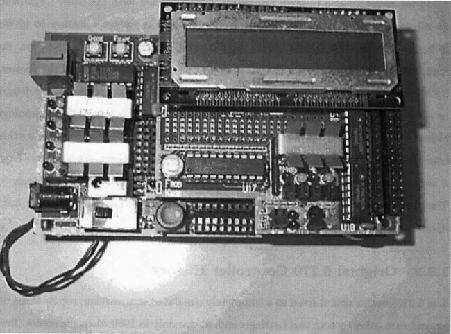
The first 6.270 controller board (shown in Figure 1-2) consisted of a Motorola 68HC11 microcontroller with 32 kilobytes of SRAM and assorted analog-to-digital converter chips, motor drivers, and input/output ports. It was programmed using assembly language; no doubt giving some contestants problems, to say the least. In
fact, conversations with some contestants from that era have revealed that the reason some of the robots that year looked and acted the same was that one team got their assembly code working, and many teams just copied them and were too afraid to try modifying it. Fortunately, the following year saw the introduction of a small inter-preter that allowed robots to be programmed using a subset of the C programming language. This environment was called Interactive C, and it made the contest much more accessible to students. The combination of a small, readily available board with an easy-to-use programming interface has made the 6.270 Controller Board, Rev. 2.21 C, one of the most popular controllers in use worldwide by hobbyists and educators.
Figure 1-2: The Old 6.270 Controller
In 1997, an attempt was made by the 6.270 organizer staff to redesign the con-troller and take advantage of technological advances made since 1990. This effort produced a good list of areas for improvement and some early concept designs, but time constraints on staff prevented them from completing the design. In the Spring
of 1998, I decided to make a new 6.270 controller as a testbed for the ideas contained in this thesis. This decision gave me a concrete target for my ideas and a way to try out the BotKit concept in a real 6.270 contest. However, the amount of effort required to engineer the hardware design and work on the BotKit framework seemed prohibitive.
1.3.3
Compaq CRL Involvement
At this point, I presented the thesis proposal was taken to the Compaq Cambridge Research Laboratory (CRL), since they were my 6A sponsors. It turned out that CRL was interested in creating a small processor board for use in mobile computing research. After some discussion, CRL decided to help sponsor 6.270 by designing and fabricating controller boards for the 1999 competition. As a result, BotKit merged
with the CRL Personal Server3 project.
1.3.4
Development Software
6.270's sponsorship by Compaq CRL took care of the hardware design work. However, the development software still needed some consideration. One of the reasons for the great success of 6.270 has been its interactive programming environment. This environment, called Interactive-C, makes development of code for robots accessible to beginners and makes development easier for advanced users. Many of the lessons learned from Interactive-C can be applied to embedded system software development in general, and any replacement environment for the contest must provide some of the benefits as well.
Interactive-C: Introduction
Fred Martin, one of the original organizers of the contest, spent some time analyzing the elements that make 6.270 special in his PhD. dissertation and found that a number of factors have contributed to its success. However, he noted that one of the major
factors that drives the entire contest is the lack of time[17]. Teams have only three weeks to build and program a robot from scratch, and that introduces tremendous pressure on the part of software developers to deliver working systems quickly.
Using traditional development tools, the compile-link-debug cycle takes far too long in the 6.270 environment because the time spent downloading new code images to the controller board significantly slows down the process of refinement. Additionally, having to compile and link code just to run a few tests discourages experimentation and tinkering. The IC environment was created to address these issues by running a C interpreter on the target platform that integrated an interactive shell. Users could then type in C code over the serial line and watch it execute immediately to get feedback.
Advantages
This interactivity allows contestants to try out new algorithms and techniques with-out the overhead of writing a test program just for that purpose. Nothing beats being able to simply call a function with some test arguments by typing in the appropriate C code and pressing "enter". For the majority of users, this is the single greatest strength of the Interactive-C environment, for it allows them to rapidly try out differ-ent parameters and test cases without resorting to writing test stubs just to exercise those functions. This shortens the development cycle considerably. The screendump in Figure 1-3 shows a session with IC.
Disadvantages
Unfortunately, one common complaint with IC is that it implements only a subset of the C programming language. In its current incarnation, programmers cannot use many C constructs that they take for granted like switch/case statements, typedefs, or function prototypes. This is not really a fault against the concept of Interactive-C itself, but against its status as a cult language. Development lags behind that of bigger vendors because it does not have the scale of support that a widespread development environment has. If there were a bigger user base for Interactive-C, this
C> printf("Hello World!");
Downloaded 9 bytes (addresses C200-C208) Hello World!
Returned <void> C> arrprint_2d(a);
Downloaded 9 bytes (addresses C200-C208)
1 10 5 50 -5 -50 2 20 10 100 Returned <void> C> arrsort_2d(a);
Downloaded 9 bytes (addresses C200-C208) Returned <void>
C> arrprint_2d(a);
Downloaded 9 bytes (addresses C200-C208)
-5 -50 1 10 2 20 5 50 10 100 Returned <void>
Figure 1-3: An example Interactive-C session
concern could be alleviated.
Also, the implementation of Interactive-C is not very portable. The interpreter is almost completely implemented in assembly language for the 68HC11 microcontroller family. This makes moving the environment to new hardware somewhat difficult unless the boards are also based on Motorola processors. With the new hardware coming online for the contest, this was viewed as the worst disadvantage of Interactive-C.
1.3.5
Final Software Specifications
With this analysis of Interactive-C in mind, a set of requirements was set out for the next generation development environment. Even though these requirements are specific to the MIT 6.270 contest, they can be extrapolated or modified slightly to encompass general embedded system requirements as well.
User Skill Level
The students taking 6.270 are generally MIT undergraduates in their freshman or sophomore year. Juniors and seniors do take the course, but fewer do because of the general increased academic workload by that time. As a result, 6.270 has traditionally drawn its entrants from underclassmen. Given the short time frame of the contest, one cannot expect the students to learn a completely new programming language that has no analogue outside of the contest. Interactive-C succeeded because it was at least somewhat like C. The replacement environment must continue this trend. In fact, it must be even easier than Interactive C, because compared to ten years ago when the contest first started a higher percentage of 6.270's entrants are not computer science majors .
Also, the environment should support both usual procedural programming and whatever new methods are introduced. Despite the advantages of state machine networks, one cannot ignore the fact that most users still feel more comfortable with procedural approaches. The goal of the environment is to make it possible to produce good code no matter what paradigms are used, not force users to use a specific one. Platform Independence
MIT 6.270 robots are programmed through a serial connection to a host PC that runs custom terminal emulation software. This terminal software has been ported to a number of platforms that contestants use, ranging from HP-UX workstations to PC laptops running Linux or Windows 95. There is no easy way to standard-ize the platform all contestants work from since there are insufficient resources to
give all contestants workstations of one type, so platform independence for any new development system is a requirement.
1.4
Robot Controller Hardware/OS Requirements
The 6.270 organizers also decided that a replacement controller should be designed for the contest. The base level of functionality was defined to be at least that of the previous MIT 6.270 Controller Rev. 2.21. On top of that, it would have to fulfill requirements set by CRL so it could be used to perform mobile computing research. After some discussion, the key parts of the controller were as follows:
" Adequate processing power for advanced research applications. This included needs for networking, speech/video processing, and the like.
" Commodity software support. By this, we did not necessarily mean a commer-cial product like Windows CE, but we were trying to avoid having to write our own operating system specifically for this controller. This contrasts with the Interactive-C environment, which is narrowly targeted towards the Motorola 68HC11 family of processors.
" Expandability through industry-standard interfaces and connectors. The base controller board was meant to be just a testbed, so expandability was very important. We also intended to use standard 3rd-party expansion modules, so we stayed away from custom interfaces.
All in all, Personal Server (the name of the controller) was meant to be a simple, configurable computing platform.
1.4.1
Hardware
The core of the Robot Controller, the new 6.270 controller, is the Personal Server (see Figure 1-4) computing platform. The Personal Server's specifications are as follows:
* Intel StrongARM4 SA110 CPU @ 200 MHz
* 16 megabytes SDRAM * 4 megabytes Flash Memory * PCI bridge
* PCI to CardBus bridge and 2 PCMCIA sockets
* PCI to Universal Serial Bus (USB) controller and 2 USB connectors
Figure 1-4: The Personal Server motherboard (3.6 inches by 5.4 inches)
For the purposes of the 6.270 contest, a daughtercard was designed to attach to Skiff as a USB peripheral and provide the I/O ports necessary for interfacing to
4
motors, sensors, etc. This robot daughtercard (RoboDC, Figure 1-5) has the following on it:
* AnchorChips EZUSB 8051+USB core, 8 KB onchip RAM * 10 H-Bridge outputs for driving motors (20 half-bridges)
* 32 analog inputs read through an analog-digtal converter, 24 of which are ac-cessible to the outside
* LCD connector and small LCD display
Figure 1-5: The RoboDC daughtercard
Together, the Personal Server and RoboDC are collectively called the RobotCon-troller (Figure 1-6). They both operate off of a 6 volt battery that powers both motors and the digital electronics.
Figure 1-6: The assembled RobotController
1.4.2
OS and Support Software
The Robot Controller boots using a custom bootloader that takes care of initializing the RAM, PCI bus, and other miscellaneous tasks. The bootloader also implements a simple command line interface over the serial port that allows users to download new images into flash, peek/poke memory locations, and perform other basic functions.
Once the bootloader is done running, it loads the NetBSD[18] kernel into memory from the onboard flash ROM and jumps. We chose to port the NetBSD operating system to the Personal Server because of its open source code, portable codebase, and working USB support. We may consider other operating systems in the future, but for now NetBSD satisfies our needs very well.
The Kaffe Java Virtual Machine5 (JVM) runs mostly unmodified on top of NetBSD. This JVM has native methods with it to access the RoboDC daughtercard over the USB connection. The native methods appear to users as part of a class library that abstracts the actual hardware to users and presents a uniform interface.
The RoboDC daughtercard itself has an Intel 8051 CPU core on it, and we make extensive use of it to offload time-intensive tasks from the main processor. In par-ticular, sensor polling, motor/servo pulse-width-modulation, and LCD control are all handled by the coprocessor. The firmware running on the daughtercard accepts com-mands over the USB bus and configures the hardware accordingly. Again, this process is transparent to the user; all the developer knows is how to call various methods in the RobotController API.
Chapter 2
Models of Computation
In this chapter we present the common problems and difficulties faced in writing robust code for embedded system and robots in particular. Then we compare the traditional programming models used for such applications, and then introduce the use of finite state machines. The advantages and disadvantages of each approach are evaluated so as to understand the design choices made in the final solution proposed in the following chapters.
Chapter 1 went over the basic challenges involved in designing and implementing an embedded system. However, the topic of software design has been left to this chapter because of its complexity. As previously mentioned, embedded system soft-ware has to be robust and interactive; the systems interact with the outside world at all times and must always respond. This stands in contrast to batch software which has all parameters specified before runtime and runs until completion with the as-sumption that parameters will not change until the run is complete. In an interactive system, events may occur at any time to interrupt, change, or even terminate the currently running code for various reasons, and the system must be capable of grace-fully reacting to these arbitrary changes in inputs and make deterministic decisions about what to do next.
It is difficult to structure code in such a way that eases the enumeration of all the possible paths of execution easy to implement and handle is a difficult task. There are several different ways to model this flow of control, each with its own advantages
and disadvantages. In the 6.270 contest, many of these approaches can be seen being implemented by various teams with different levels of expertise, so this chapter will
use 6.270 robot code as an example case.
2.1
The Line Follower
As an example, let us consider a robot that is driving along the playing field and is trying to follow a black line painted onto the table. This line is for the most part straight, but may have curves or even 90-degree turns in it. For the sake of realism, let us also say that the purpose of following this line is to collect balls on the line's path and score points.
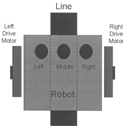
The robot has two drive motors, one for each side (left and right). In this way, it drives much like a tank - to turn left, just run the left motor at a slower speed than the right motor, and vice versa for turning right. For sensors, the robot starts with three light-sensitive detectors that can "see" a black or white surface. We can assume for simplicity's sake that some preprocessing code takes the analog sensor reading and turns it into a digital "white" or "black" reading with a fair degree of accuracy. These sensors are placed in a row such that if the robot is centered over the line, the sensors completely span the line as shown in the diagram (see Figure 2-1).
Let us assume that the robot starts centered on the line, i.e., the two outside sensors report that they are on the white table, but the middle sensor is on the black line. Now, the task is to follow the line for as long as possible and scoop up balls with the aid of a vacuum-cleaner-like attachment to its front.
There are many possible ways to solve this problem, but the most common algo-rithms are essentially feedback loops that correct the speeds of the motors on each side of the robot to keep positioning the sensors on top of the line at all times. If the left sensor falls off the line, a slight adjustment to the right is made, and so on. Of course, in practice this problem is much more complex than it seems. In the following sections, we will attempt to implement this algorithm using different methodologies and expose the most common pitfalls for each.
Line
Left
Right
Drive
Drive
Motor
Motor
Figure 2-1: Note the position of the sensors such that the outside sensors are on the white surface while the middle sensor is on the line.
2.2
Procedural Models
Most introductory programming classes start students off with basic concepts of pro-gram flow. They show how to break complex tasks into procedures, and also in-troduce concepts like loops, conditional statements, etc. Most software engineering classes tend to teach students how to write batch-mode programs. In other words, the programs normally assigned for homework are structured such that they read in some input, operate on it, output the result, and exit. Dividing such a program into procedures helps to reduce the apparent complexity of the code and increases reusability.
This approach is easy to learn and works well for the majority of projects. Splitting the pieces of a program into procedures and establishing a clear flow of data through the program from procedure to procedure definitely makes for a legible diagram. However, if the number of distinct code paths is high, the system can get confusing. This increases the complexity of the implementation and the possibility for mistakes
and necessitate more time spent in debugging the code.
2.2.1
Implementing the Line Follower
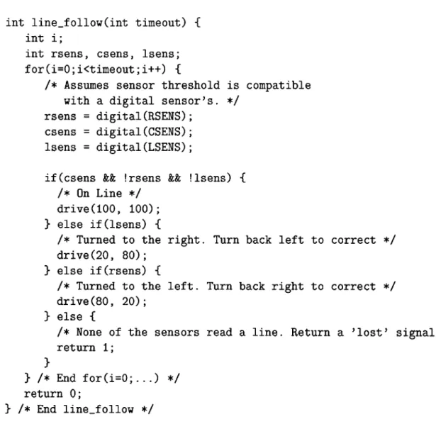
Using conventional methods, one might implement the line follower using the following algorithm (Figure 2-2). A variant of this code snippet is introduced in the first lecture of 6.270 every year as an introduction to feedback loops. It has been our experience that most students can understand a piece of code like this within a fairly short span of time, but more complex examples tend to make people miss the overall idea. Hence, we start with this implementation.
2.2.2
Analysis
This algorithm revolves around a fixed feedback loop in the center that continually checks the state of the sensors and makes adjustments to the drive motors based on sensor results. Even in this naive form, the algorithm actually does work, and a robot programmed in this manner is capable of following a reasonably straight line down a table. The code is still fairly easy to understand as well.
However, throw in a more complex situation and the problem space exponentially increases. For example, the above example has only one degree of correction - no matter how far the robot is off the line, the code will only rotate the robot at a certain rate. If the distance being traveled is large, that is acceptable, but for a short trip this feedback parameter does not work. The robot will run out of room before it gets back on the line. However, one cannot simply turn the feedback rate up, because then the robot will likely over-correct for minor course deviations and proceed to oscillate back and forth across the line.
The solution to this demands some sort of proportional feedback mechanism that varies the amount of correction based on how far the robot is off course, and how quickly it is traveling. The robot's speed is important because the rate of correction is also heavily dependent on movement speed - steering input is amplified much more at high speed.
int linefollow(int timeout) { int i;
int rsens, csens, lsens; for(i=0;i<timeout;i++) {
/* Assumes sensor threshold is compatible with a digital sensor's. */
rsens = digital(RSENS); csens = digital(CSENS); lsens = digital(LSENS);
if(csens && !rsens && !lsens) { /* On Line */
drive(100, 100); } else if(lsens) {
/* Turned to the right. Turn back left to correct */
drive(20, 80); } else if(rsens) {
/* Turned to the left. Turn back right to correct */ drive (80, 20);
} else {
/* None of the sensors read a line. Return a 'lost' signal */
return 1; }
} /* End for(i=0;...) */ return 0;
} /* End line-follow */
Figure 2-2: This fragment is presented to 6.270 contestants on the second day of class every year. Thanks go to Robert Blau (robblaudmit.edu) for contributing this version.
Implementing this improved feedback mechanism within the existing framework is possible; the result is significantly more complex and harder to read, but the basic flow of control is the same. However, this code still assumes that the robot is not doing anything else while it is moving down the table, and furthermore, that following the line is a goal to be pursued without caring about other external events that might occur before the line ends.
In real life, that sort of idealized situation rarely happens. It could be that the line is just a guide, and the robot is supposed to stop after a certain distance and
turn off the line or do something else. The procedure could be modified to check the distance traveled each time through the loop and return once that distance has been traveled. But what if the robot never makes it there? It could get stuck, or the wheels might spin on a slick surface, or any number of things. Hence, a timeout mechanism is needed. Additionally, a 6.270 contest table is rarely that simple to navigate. Paths on the table are often obstructed by blocks, lines are rarely perfectly straight, and the sensors themselves are usually not optimal.1 More code is added to the main loop to check for a time-elapsed function, and the list goes on...
The end result of all this is that the original line follower procedure has gained so much complexity and extra functionality that it has become hard to follow. This makes it harder for a developer to make additional modifications or debug the code, and greatly increases the likelihood of unforeseen test cases.
Most 6.270 contest robots have been coded this way since the contest was started. In our experience, this methodology is easy to learn at first and works well when contestants are preoccupied with learning basic parts of robot control, but when integration into a contest-ready piece of software occurs everything tends to break all at once. It seems that the main problem here is the difficulty involved with controlling multiple inputs and outputs on a robot with only a single flow of execution. Single-threaded systems must by necessity visit many different sections of code one at a time and take care of business before going on to the next procedure. However, this makes the systems difficult to code and debug.
2.3
Multithreaded Procedural Code
One way to reduce the complexity of a big monolithic control loop is to split the relevant sections into their own loops and run them simultaneously. This requires the code to become multithreaded either preemptively or cooperatively. However, the overall complexity of the system increases and requires higher effort to implement 'It probably would help if we did not have to buy them at the surplus store. If anyone reading this thesis would like to help the contest, please send money so we can get better stuff.
and debug, as is shown in following paragraphs.
Implementing this scheme helps by allowing multiple threads of execution to run at once. There is no large "main loop" through which all execution flow has to pass, and the individual loops that run by themselves are easier to code and understand. In the case of the line follower example, the code controlling motor movement can now run independently of the code that checks for collisions or monitors timeout conditions.
This solution seems ideal at first, but in real life it has proven to be very prob-lematic. Multithreaded programming is a very difficult task. This barrier has kept many developers from taking advantage of this paradigm. Having to keep track of what different threads are doing at the same time and coordinate interactions between threads using primitives like message queues and spinlocks requires an extremely high learning curve for most developers. This barrier to entry makes it impossible for most 6.270 contestants to use multithreaded code properly, especially since more and more contestants are entering with no previous programming experience. Mistakes are com-mon even for experienced developers, and bugs are sometimes almost impossible to find because of the many intricate cases that may occur at any point during runtime to crash a multithreaded program.
Anecdotal evidence of the problem with multithreaded code can be found in 6.270's history. 6.270's Interactive C programming environment has had support for multi-threaded functions since its debut. The default code for robots that the organizers supply to contestants includes one thread routine to automatically shut the robot down after 60 seconds. Many teams each year try to take advantage of even more threads, but most of them revert back to single-threaded algorithms by the time they submit their robot for final competition. A rough estimate gathered from the past three years of contest code shows that of 150 teams, only about 40 ended up entering multithreaded final contest code (excluding the built-in start/stop thread provided by organizer staff).
Viewing a complex interactive system in terms of separate procedures generally causes problems regardless of a single or multi-threaded implementation. The
diffi-culty inherent with expressing embedded system behavior stems from the multiple paths control may take through the same code. Accounting for all these paths and expressing the flow of control in what is essentially still a single-path paradigm is difficult because there is no clearly defined begin and end state in these systems.
2.4
Finite State Machines
One way to reduce the confusion is to outline the different code paths before im-plementing them in code. A state diagram is one such method used to model a system and compress multiple combinations of inputs and outputs into a succinct representation. By presenting the different positions of the system in various combi-nations and enumerating how the combicombi-nations can lead to each other via different types/numbers of inputs, a table emerges that effectively captures all the possible states of the system.
A formalized visualization of this concept leads to finite state machines or FSMs. A FSM is most simply described as a set of input events, a set of output events, a set of states, and a set of transitions. Consider the example shown in the following Figure 2-3. This diagram shows an FSM with input events [a,b] and outputs [u,v]. Each node represents a state, and the connections (arcs) between states represent transitions[10]. State machines have to start in some initial state, so the arc without a source state pointing to the initial state does not actually represent a transition, but is more of a pointer.
There must be a way to determine whether to take a transition or not. This takes the form of a boolean expression over the input events that is attached to each transition. The expression is called a guard. When the expression evaluates to be true, that particular transition is taken, the current state shifts to the destination of that arc. For some transitions, there is an action/output when they are taken. These actions are attached to the guards.
b/v
a/u
Figure 2-3: A simple finite state machine. This diagram comes from Girault, Lee, and Lee's paper on hierarchical FSMs[13]
2.4.1
Advantages
The main advantage of a finite state machine is its ability to represent many possible execution paths in a compact manner. Each state may have its own table of tran-sitions, with their own trigger guards and actions, and this helps to encapsulate all possible behavior in a specific realm of the problem space. By isolating the system into a network of states, one can focus on a particular state and its relationship to other states without having to worry about the others. In practice, this makes imple-mentation much easier because it segments the system by states, and states can be added or deleted from the system piecemeal without too much effort. All one must do is follow all transitions coming into and leaving that state and modify the tables in the connected states accordingly.
Most finite state machines are implemented by means of a core "event loop" that continually reads the inputs and updates the current state accordingly. This core loop is easy to understand, and more importantly, does not need to be modified a new state is added to the system. All of the complexity in a finite state machine is hidden in the initial setup, so understanding the flow of execution is easy once the state diagram is drawn. This gives FSMs an advantage in development over the mess of nested conditional statements that characterize procedural code.
Going back to the line follower example, Figure 2-4 exemplifies how one might convert the system into a state diagram. The inputs to this state machine are the sensors, and the outputs are the commands sent to the drive motors. One can enu-merate the possible states of this system through noting that staying on course means trying to remain in the state where the sensors straddle the line. Starting from there, the transitions which can occur (veering left or veering right) are easy to come up with. For most people this diagram is much easier to understand than the raw code or even flowcharts that the procedural methods produce.
Default State - Straddling line
Slightly off to the left
Common States
& 0Slightly off to the right Lost (completely off line) At an intersection or on the line lengthwise
Uncommon States
Facing an intersection at a 45-degree angle
Figure 2-4: Some of the possible states the sensors can be in for the line follower. Note that two of the states in the figure correspond to odd situations that would be hard to catch otherwise if one were to just start writing the code without thinking the problem though first.
2.4.2
Disadvantages
However, FSMs are not without their drawbacks. FSMs are easy to implement, but it is not quite so easy to come up with the state diagrams in the first place. Reducing a system down to a collection of states requires some thought and is somewhat difficult to do for an inexperienced developer. Most computer science students are taught to
break problems down into smaller pieces and solve them using procedural methods; they have less experience breaking problems into state instead.
Experience with the MIT 6.270 competition has shown that finite state machines work well in the classroom with pre-meditated examples and clearly articulated sys-tems, but when contestants attempted to use the same principles in real robots the state diagrams got extremely large and unwieldy. The problem is that for a single task, state machines model the system extremely well. However, there can only be one active state in a state machine at any given time. This makes modeling of multiple concurrent tasks difficult; the FSM must rapidly transition between states relating to the different tasks to keep them all moving at the same time. As a result, the FSM methodology exhibits the same problem that single-threaded procedural code does, even though the initial modeling step is easier.
2.5
Multiple Concurrent FSMs
The natural extension is to run multiple FSMs in parallel using separate threads of execution. Running multiple FSMs allows the individual FSMs to be fairly simple; yet, having the FSMs work in concert allows the system to express complex behavior as if it were run using a single very big FSM. Keeping the pieces small and in separate FSMs reduces the effort necessary for users to integrate various portions of their code together and helps solve the concurrency issue raised by modeling multiple tasks.
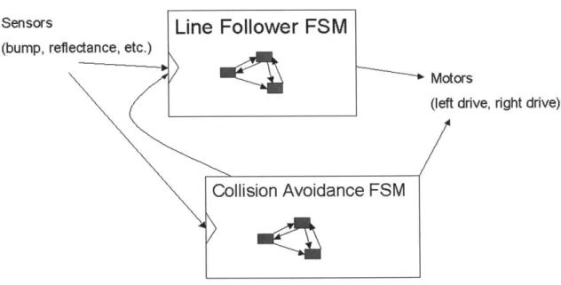
Going back to the line follower example, let us now try adding more complex behavior to the system. If we also want to track how far the robot has traveled and take action based on that, more guards and actions could be added between the existing states. However, this makes the input and output vectors get larger and more complicated. Instead, a separate state machine that has only distance measurements as inputs makes the picture much simpler (see the Figure 2-5). The output of this second state machine then becomes an input to the first, linking the two FSMs together. A network of FSMs now exists that exhibits more complex behavior than the original, but the original FSM has not changed or gained complexity.
Sensors
Line Follower FSM
(bump, reflectance, etc.)
Motors
(left drive, right drive)
Collision Avoidance FSM
Figure 2-5: An example FSM network
Networks of FSMs have recently come to the fore as a promising new way to model reactive systems[12]. A lot of recent work in this field has come out of the Ptolemy Project[8] at the University of California, Berkeley. In particular, an in-depth look at the combination of finite state machines with multithreaded environments produced a working system that is capable of modeling complex real-time systems, particularly in the field of digital signal processing[1]. Prior attempts to take advantages of FSM networks are documented in papers on robotics, real-time operating systems, and other applications.
However, running multiple FSMs concurrently raises the issue of complexity from a different perspective. If all the different state machines operate independently of each other and have no need to communicate, the implementation is simple -just set up the different threads and let them run. But if the FSMs depend on each other, some sort of inter-FSM communication mechanism is required. I attempt to address this issue in Chapter 4.
Chapter 3
The Subsumption Model
In the previous chapter, we went over various ways of breaking embedded systems into manageable pieces and implementing robust control loops for them. In this chapter we present the solution arrived at for use in BotKit, which makes use of the subsumption architecture[7].
3.1
Introduction
Finite state machines ease the task of expressing multiple execution paths, but devel-opers still face the task of deciding how to model a system. Real-world systems often do not easily break down into networks of finite state machines because the states are heavily obscured by minute details of interaction. A way of viewing a system that encourages decomposition into smaller systems was needed so it could be applied to the robot contest.
Rodney Brooks from the MIT Artificial Intelligence Laboratory ran into much the same problem in the course of his own research in robotics during the early 1980s. Brooks chose to decompose systems based on observal external behaviors (see Figure 3-1) [2]., Brooks chose to instead decompose the system based on its observable external behaviors[2]. This results in a horizontal breakup of the system into layers that completely span from raw sensor inputs to observable outputs, which stands in contrast to traditional models that split the task vertically and insulate layers from
Output
Level 3
Registers
Level 2 -Level 1
Sensors
Level 0
Actuators
Behaviors
Figure 3-1: Layers of control are stacked horizontally so that lower-level layers by default have control unless higher-level layers take over. Output registers combine inputs from the multiple layers and either sum or choose inputs to present what goes to the outside actuators and motors. Note that one can take off the higher layers and still have an operational system. This figure is taken from Brook's paper "A Robust Layered Control System for a Mobile Robot" [2]
each other through abstraction barriers.
Brooks' contention was that breaking the systems up horizontally allows one to concentrate on making a robot perform a specific behavior and do it well, then incre-mentally add functionality in the form of more specialized behaviors. Additionally, each higher level of behavior includes as a subset some or all of the lower levels. Since higher levels include lower levels, the higher level behaviors can be seen as a top-down enforcement of design constraints on the lower levels, providing an overall structure to the program[15].
3.2
Advantages
This architecture emphasizes the independence of each behavior - developers create each behavior and complete it before moving on to the next. By debugging lower-level behaviors completely and then leaving them alone, higher-level behaviors are able to assume some base level of functionality before modifying the observable outputs to create more complex actions. In the event that higher-level behaviors are incorrect or produce output at the wrong times, the higher-priority lower level behaviors will
still produce mostly sensible results[4]. Essentially, the low-level behaviors step in for the system states that are undefined or poorly handled by high-level constructs.
Returning to the line follower example, let us attempt to break this problem down using behaviors (see Figure 3-2). The most obvious behavior in the system is the robot's attempt to stay on the line. The inputs to this behavior are the light sensors under the robot, and the outputs are the motors. This behavior is the default one given normal operating conditions. But as previously noted, this system must be capable of handling adverse conditions enroute to accomplishing the primary goal of following the line.
Inter-FSM
communications
Override Connection
(top-level guidance)
Slightly higher
Distan
Marker
priorit DriveMotors
Sensors
~Line Follower DfutPirtCollision Avoidance"
Connection
Behaviors (emergency use)
Figure 3-2: Note that the base behavior just has the robot avoid hitting walls, and at the top leve a path planner picks which lines to follow. Behaviors also communicate directly with each other to exchange state and data.
The adverse cases can be controlled by other lower-level and high-level behaviors. For example, a base behavior may want the robot to avoid getting hung up on walls, so its response to bump sensors is to back away. Since this behavior is important for robot safety, one may set the priority of this behavior somewhat higher than the others. By having this behavior run concurrently with the line follower behavior,
a combination of the two behaviors is achieved with minimal effort to actually link the two. Note that each of the two behaviors operates independently; the only link
between them is the ability of one to override, or inhibit, the actions of the other when push comes to shove. This sort of behavior layering leads to a more robust system because developers can worry about high-level thinking at one level and safely assume that base cases are still covered by lower-level behaviors[6].
Another positive side effect of modeling systems in this way is that sensor inputs are exposed in their raw form to all levels of behaviors. This allows each behavior to treat sensor data in a way that is useful to it without having to worry about other behaviors' needs. This contrasts with the approach of encapsulating all sensor input into one procedure that has to provide relevent interpretations of data to all layers above it. Such an approach leads to an overly-general and non-optimal solution for all the layers on top because no one solution can be perfect for all.
Additionally, each behavior layer has optional direct access to the system inputs and outputs. For those outputs that need to be shared among different behaviors, output registers can combine outputs from multiple FSMs and decide how to present the results to the actuators. Furthermore, these registers need not be present at the
very end of the loop; they can be interspersed between different layers and handle very specific situations. This solves the problem of implementing a generic signal "combiner" at the end of the decision cycle needed in other schemes. With a vertical separation of inputs/outputs away from other layers, the code needed to process inputs for one layer must be fitted to also meet the requirements of other modules, and this leads to overly general abstractions that are not useful. Using subsumption allows the input/output processing to be tailored to each layer without worrying about side effects on other layers. However, communication between layers is not hindered, because the behaviors can still influence each other by connecting outputs from some layers to inputs on other layers.


![Figure 2-3: A simple finite state machine. This diagram comes from Girault, Lee, and Lee's paper on hierarchical FSMs[13]](https://thumb-eu.123doks.com/thumbv2/123doknet/14180851.476239/35.918.178.583.111.397/figure-simple-finite-state-machine-diagram-girault-hierarchical.webp)