HAL Id: cea-02430090
https://hal-cea.archives-ouvertes.fr/cea-02430090
Submitted on 7 Jan 2020
HAL is a multi-disciplinary open access
archive for the deposit and dissemination of
sci-entific research documents, whether they are
pub-lished or not. The documents may come from
teaching and research institutions in France or
abroad, or from public or private research centers.
L’archive ouverte pluridisciplinaire HAL, est
destinée au dépôt et à la diffusion de documents
scientifiques de niveau recherche, publiés ou non,
émanant des établissements d’enseignement et de
recherche français ou étrangers, des laboratoires
publics ou privés.
Evaluation of damage in neutron irradiated boron
carbide
Dominique Gosset, Patrick Herter, Vianney Motte
To cite this version:
Dominique Gosset, Patrick Herter, Vianney Motte. Evaluation of damage in neutron irradiated boron
carbide. Nuclear Instruments and Methods in Physics Research Section B: Beam Interactions with
Materials and Atoms, Elsevier, 2018, 434, pp.66-72. �10.1016/j.nimb.2018.08.021�. �cea-02430090�
A R T I C L E I N F O
Keywords: Neutron absorber Damage rate Boron carbide
Ion implantation simulation
A B S T R A C T
When irradiated in a reactor, neutron absorber materials undergo two different damages induced, first, by the elastic scattering of neutrons; second by the neutron absorption reactions. In boron carbide irradiated in a fast neutronflux, neutron scattering and the slowing-down of He and Li arising from the (n,α) absorption reaction both lead to the displacement of B and C atoms which energy ranges up to a few MeV. Simulating the neutron damage by ion irradiation requires the calculation of the damage produced in both cases. In this paper we propose an estimation of the actual defect production rate resulting from the fast neutron irradiation. For this, wefirst estimate the energy spectra of both the primary knocked-on atoms and atoms created by the absorption reactions, here in a Phenix-like neutron spectrum. We then deduce from SRIM calculations the actual energy distribution of all the atoms displaced along the displacements cascades induced by those primary projectiles. At last, we obtain an estimation of the number of displaced atoms per produced helium, about 305, most of them resulting from neutron scattering. This is far from a Kinchin-Pease or NRT estimation, of the order of several thousands, this arising from the fact that most of the energy is dissipated through electronic interactions. Such results are then used in order to perform ion irradiations aiming at a realistic simulation of synergetic effects of helium implantation and damage production.
1. Introduction
Ion implantations are widely used to simulate the damage and the composition change arising in materials irradiated in nuclear plants [1,2]. However, some parameters can hardly be accounted for; for ex-ample, a reactor irradiation most often last up to a few years to be compared to a few hours for an ion implantation, this making kinetics effects difficult to handle. Another parameter is the way the energy is dissipated into the material. The slowing-down of the particles happens according to two different processes[3]; either an interaction with the electrons (electronic slowing-down, associated with the electronic stopping power, Se) or with the nuclei (nuclear stopping power, Sn). The former is of low consequences in metals (energy dissipation in the electron sea) but can induce important effects in insulators or semi-conductors [4]. Moreover, in some conditions, nuclear reactions happen (fuel, neutron absorber, tritium blankets in ITER, spallation sources…). In those cases, first the composition of the material is modified, but second the reaction products can be energetic enough to produce defects.
We are here interested in the behavior of helium in boron carbide. Boron carbide is widely used as a neutron absorber, either in thermal or fast neutronflux[5]. The main absorption reaction is the10B(n,α)7Li
one. In fast neutron reactor, helium can be produced in large quantities, about 1022/cm3(i.e. concentration about 0.1), leading to swelling and cracking of the material.4He and7Li are emitted with energies in the MeV range (mass defect of the main absorption reaction). Owing to the low atomic mass of the constituents of the material, they can then produce structural defects. On the other hand, in a fast neutronflux, the primary knocked-on atoms (pka) produced by neutron scattering have an energy spectrum up to a few MeV, high enough to displace the atoms of the material. In both cases, neutron absorption or scattering, the nuclei emerging from the reaction are light ones (B, C, Li, He). They will slow-down in a matrix also constituted of light nuclei. In that case, it is known that most of the pka energy is dissipated by electronic interac-tion. However, some atomic displacements arise, mostly at the end of the ion paths. The questions which arise are then the ratio of produced helium to the total number of displaced atoms, the way energy is dis-sipated, and the consequence of the damage on the kinetics of helium, e.g. nucleation and growth of clusters.
Simulating the behavior of helium in boron carbide with ion im-plantations then leads to wonder if the associated damage in reactor can be reproduced as well as the gas concentration. For that, it is necessary to perform ion irradiations which parameters such as the damage to helium concentration ratio or the Se/Sn ratio are precisely known and
https://doi.org/10.1016/j.nimb.2018.08.021
Received 20 November 2017; Received in revised form 7 August 2018; Accepted 17 August 2018
⁎Corresponding author.
E-mail addresses:dominique.gosset@cea.fr(D. Gosset),patrick.herter@cea.fr(P. Herter),viamotte@hotmail.fr(V. Motte).
Available online 25 August 2018
representative. Such estimations can be done e.g. with tools such as SRIM [6]. But the comparison with the reactor conditions requires making this estimation with the actual reactor parameters. The avail-able data are the material characteristics, the neutronflux in the reactor and the interaction cross sections. Here, we detail the route we have followed from those nuclear data to the atoms displacement rate (ob-taining the helium production rate is straightforward, by convoluting the neutron spectrum and the absorption cross section). Thefirst step is calculating the so-called primary damage spectrum[7–9], i.e. the en-ergy distribution of the pka and of the created atoms by the absorption reactions. We then use the SRIM software to estimate the number of displaced atoms as a function of the pka’s energy and the way energy is dissipated. At last, those results allow us to estimate the helium to atomic displacements ratio and the electronic stopping power range. 2. Data
We consider a neutron spectrum equivalent to the one in the center of the late French Phenix LMFBR (sodium cooled fast neutron reactor) [10]. The spectrum is divided in 36 groups (Fig. 1). The totalflux is about 3.1015n.cm–2.s–1.
The neutron interaction cross sections (neutron scattering and ab-sorption) are taken from the ENDF data base[11]:Figs. 2 and 3. For the absorption reactions, we consider only the 10B(n,α)7Li one. We then neglect the10B(n,2α)3H reaction. As a matter, the cross section for this reaction is about 10−6lower than the (n,α) one, excepted in the fast neutron range (where it is rather poorly known[12]), where the neu-tronflux significantly decreases, leading to a production rate about one thousand lower than the (n,α) one. Second, it has a lower mass defect, about 0.23 MeV to be compared to about 2.8 MeV for the (n,α) reaction, leading to a much lower energy of the pka’s. Excepted in the fast neutron range, the (n,α) absorption cross section varies as σ = 611/√E (σ in barn, E in eV). Convoluting the neutron spectrum and the (n,α) absorption cross section leads to the helium production rate:
= × − − −
τHe 4, 01 10 9at . s1 1
where‘at’ stands for an equivalent boron carbide atom (initially full density B0.8C0.2, 48%10B enriched, 1022/cm3burnup: see here under). In order to have a good estimation of the damage on all the atoms, including the neutron capture products, we consider a highly irradiated boron carbide sample. We have chosen a 1022.cm−3capture density (most often called burnup). The boron concentration in non-irradiated B4C boron carbide is about 1.1x1023.cm−3. As a result, the mean atomic composition of the irradiated material is taken as B0.72C0.2He0.08Li0.08.
The initial10B enrichment of boron is taken as 48%, which reduces to 39% for a 1022.cm−3burnup.
Estimating the atom displacement rates requires the knowledge of the displacement energy threshold (TDE) for all the atoms of the ma-terial. Here we consider only mean values. For B and C, we have con-sidered the values proposed in SRIM, which are coherent with the es-timations performed by Zuppiroli et al.[13]. For He, we have used a most recent estimation of the thermal diffusion energy[14]. For Li, we have used an arbitrary, intermediate value: the only available value is for lithium aluminate, about 22 eV, i.e. in a quite different electronic environment with strong ionic bondings we have supposed higher than in B4C[15]. Now, on a formal point of view, this value is of low im-portance: Li emitted with energy close to the TDE is unable to displace B or C and is of low efficiency on He. The values are then the followings:
•
B: 25 eV•
C: 28 eV•
He: 2 eV•
Li: 15 eVFig. 1. Neutron spectrum at the center of the late French Phenix LMFBR[10]. Fig. 2. Neutron scattering cross sections on the isotopes to be considered,10B, 11
B,12C,7Li,4He, from[11].
Fig. 3. Neutron absorption cross section for the10B(n,α)7Li and10B(n,2α)3H reactions, from[11].
D. Gosset et al. Nuclear Inst. and Methods in Physics Research B 434 (2018) 66–72
by a neutron of mass m and kinetic energyEwill get a kinetic energy E which probability density function f(E’,E) is uniform from 0 to a max-imum energy given by:
′ = Emax γE with = + γ Mm M m 4 ( )2
Integrating the contribution of all the neutrons through the whole spectrum ϕ withσelastthe elastic cross section leads to the number of pka per second and pka energy unit given by:
′ ′ = ∫⩾ ′ − − − dN dE γ ϕ E σ E dE E 1 ( ) ( ) (at . s . eV ) E E γ/ elast 1 1 1 (1)
3.2. Energy spectra of produced He and Li
The He pka kinetic energyE′resulting fromfission induced by a neutron absorption of10B does not only depend on thefission energy but also on the impacting neutron kinetic energy E. In the center of mass referential, He is emitted with about 1.8 MeV and Li with 1.0 MeV. Those energies have to be evaluated to take into account the energy of the impinging neutron and its space distribution. We assume that the loss of mass due to thefission is negligible. Conservation laws of energy and momentum lead to formulas depending both on the masses of the parent isotope10B (M) and thefission products4He (mHe) and7Li (mLi). Let the two characteristic energies be:
=
+
E0' EfissionmHemLimLi (He energy resulting from a neutron of null en-ergy, equal to the value in the center of mass referential)
= +
E0 EfissionmmLiMmm
He (neutron energy leading to a He staying at rest
after its creation)
The kinetic energy E'of the created He may be expressed in the following form: = ⎡ ⎣ ⎢ + + ⎤ ⎦ ⎥ E E E E E E cos πX 1 2 (2 ) ' 0' 0 0
where is a uniform random number between−1 and +1 (due to the isotropic recoil direction in the mass center coordinates), which leads to a probability density function of the pka energy E'given by the formula:
= f E E E ( , ) 1 4 . E E ' 0' 0 (2)
where E'ranges between ⎛
⎝ − ⎞⎠ E E 1 E 0' 2 0 and ⎛ ⎝ + ⎞⎠ E E 1 E 0' 2 0
For a whole neutron spectrum ϕ and an absorption cross section σabs this leads to a number of He created per second and He energy unit given by
∫
= ⎛ ⎝ ⎜ + ⎞ ⎠ ⎟ ⎛ ⎝ ⎜ − ⎞ ⎠ ⎟ − − − dN dE ϕ E σ E dE E at s eV ( ) ( ) 4 ( . . ) E E E E E E abs E E ' ' 1 1 0' 1 1 1 0 ' 0' 2 0 ' 0' 2 0 (3) Similar formulas are derived for Li.Calculation are performed by a numerical method with a log scale for the energies (lethargy units).
4. Results 4.1. Primary spectra
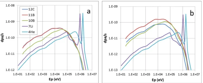
The primary spectra for the different isotopes are reported onFigs. 4 and 5. They span from the eV range (depending on the threshold dis-placement energies) to the MeV range (depending on the atom mass over neutron mass ratio). In the case of helium (lithium is similar), Fig. 4clearly shows the two components: displacements by the neutrons (“elastic” component) and energy distribution of He produced by the absorption reaction (“fission” component). The latter is proportional to He concentration and is here calculated for a He concentration of 1022/ cm3. Taking into account the energy distribution of the absorbed neu-tron, He atoms (resp. Li) are emitted with an energy distribution spanning over several energy groups of the neutron spectrum. OnFig. 5, the curves are limited on the low energy side by the threshold dis-placement energies. The steep decrease of the curves on the high energy side justifies not having taken into account the10B(n,2α)T reaction. Integrating the primary spectra curves shows that most of the pkas have energy above 10 keV (Fig. 6).
This calculation can then be used to estimate the pka formation rates (Table 1).
4.2. Displacements induced by pka’s and created atoms
After calculating the primary spectra, it is necessary to estimate the number of displaced atoms of each species as a function of the pka’s energy. For that, we used the SRIM program in the“full cascade” mode [6]. This allows an estimation of the number of the displaced atoms by a given incident ion, including the sub-cascades, and of the way energy is dissipated. Calculations are performed with 5000 ions in each case. The material is simulated with the composition we detailed above, then with an equivalent boron atom with a 10.6 atom mass. For the sake of
Fig. 4. Primary spectrum for He, showing the contribution of the neutron scattering (elastic) and absorption (for a He content = 1022/cm3).
simplicity, those calculations have been performed on a few pka en-ergies evenly distributed along a pka energy logarithmic range from 100 eV to 4 MeV.
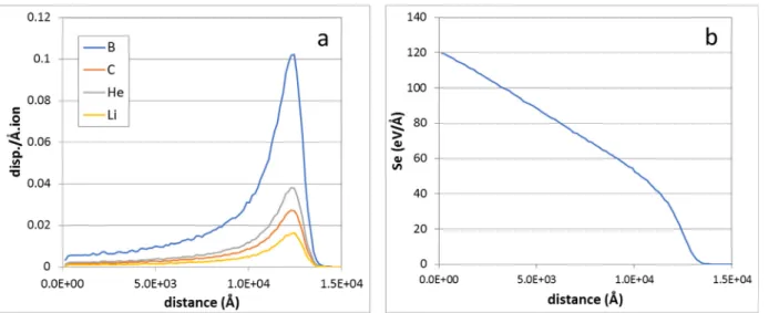
OnFig. 7we reported the results of the SRIM calculation in the case of a12C ion with a 1 MeV initial energy. As emphasized above, it ap-pears most of the energy is dissipated via electronic interactions:Fig. 8. Atoms displacements occur mainly at the end of the C path or for a C primary atom energy lower than 10 keV. Due to the mass ratio and threshold displacement energies, the relative displacement yield of helium appears much higher than the B or C ones.
In the case of low-energy pka’s, SRIM leads to a non-negligible number of back-scattered atoms. In the case of a reactor irradiation,
those atoms correspond to ones emitted in a backward direction. Their energy can however be high enough to produce defects in a bulk ma-terial. To take into account this contribution, we have extrapolated the ‘range’ profiles as calculated by SRIM towards the negative paths, as-suming Gaussian-like profiles (Fig. 9). The displacements rates have then been increased in the surface of the Gaussian over surface of the range curve ratio.
The results we obtained for each impinging atom are reported on Fig. 10. Here again a high mobility is observed on He, due to its low atom mass. Polynomialfittings of the results have then been performed. Those polynomials are then convoluted with the primary spectra, this leading to the total number of displaced atoms:Table 2.
As mentioned in Section 2, the helium production rate is about 4.01.10−9s−1per equivalent B4C atom. From those results, we deduce the number of displaced B and C atoms per produced helium (i.e. (973 + 252)/4.01) is about 305, and 280 when neglecting the damage induced by the slowing down of He and Li produced in the (n,α) re-actions. This second contribution is then less than 10% (it is worth noting that this contribution would become the main one in a thermal neutronflux). This is far from an estimation in the Kinchin-Pease or NRT (Norgett-Robinson-Torrens) approximations[16,17]which lead to a displaced atoms over produced helium ratio of several thousands (at first order, the pka yield is evaluated by the pka energy divided by twice the threshold displacement energy). Again, this is due to the fact that most of the energy is dissipated through electronic processes.
Regarding the electronic energy losses, their intensity has to be examined. As a matter, depending on this intensity, this contribution can either produce damage (e.g., tracks in insulators), heal the material [18]or have no noteworthy effect. Here, the electronic stopping power is at maximum 160 eV.Å−1for C, 125 eV.Å−1for B, 75 eV.Å−1for Li and 45 eV.Å−1for He for the highest primary atom energy. This can certainly not lead to damage (the usual threshold value for producing damage is about or higher than 1 keV.Å−1) but could possibly allow a low healing of some defects. This could be studied by tuning the Se over Sn ratio at constant Sn value: this could be achieved by performing dual beam experiments (cf. infra).
4.3. Application
We have then evaluated the damage produced by different ions of different energy (see[19]for the choice of some ions) to estimate the possibility of reproducing the damage evaluated in the previous section (Table 3.).
From the previous estimations, it appears that reproducing the
Fig. 5. Primary spectra for all the isotopes in irradiated B4C, for an initial10B enrichment = 48% and a 1022/cm3burnup. a: per isotope;12C and11B show very
similar profiles. b: reported to an equivalent B4C atom with 1022(n,α)/cm3.
Fig. 6. Integral weighed primary spectra for B4C (1022/cm3burnup) in a
Phenix-like neutron spectrum. Most of the pka’s have energy above 10 keV. The steps at about 1 MeV on the He and Li curves correspond to the (n,α) con-tribution.
Table 1
pka formation rate for all the isotopes in irradiated boron carbide for an equivalent B4C atom (10B enrichment = 39%, He = Li = 1022.cm−3).
Pka.s−1(x109) 12C 11B 10B 7Li 4He
2.34 4.90 2.83 0.79 0.82
D. Gosset et al. Nuclear Inst. and Methods in Physics Research B 434 (2018) 66–72
damage arising in a fast neutron reactor with ion irradiation in boron carbide requires a high ballistic component together with low elec-tronic losses. This can be achieved by using slow heavy ions. But in this case, the ion range is very short and the damage zone is strongly su-perimposed to the implantation one, which is not desirable. This is of course no longer acceptable if helium has to be implanted in the da-mage zone. An acceptable compromise is to use heavy ions with in-termediate energy (a few MeV): in that case, the ballistic damage can be made realistic and the electronic slowing down is a bit too high but still far from the range where specific damage such as ion tracks appear [19]. In the case of dual-beam experiments, it is worth noting that we are interesting in creating a realistic damage in the zone where helium is implanted. We then only consider the atom displacements in the damage region of the slowing-down of the heavy ions, not in the stopping region. As a consequence, the structure of the damage, i.e. the space distribution of the displaced atoms does not include all the cas-cades. This is an important point to consider since it is known that the largest cascades are produced at the end of the heavy ion course: in the damage region, most of displacements arise from small cascades which structure is rather close to those created by the stopping of the matrix
atoms in the reactor, i.e. B and C with energy up to a few MeV. Preliminary tests have been performed[20,21]aiming at reprodu-cing the helium to damage ratio together with a significant helium concentration. We have irradiated a high density boron carbide sample with a dual beam on the Jannus-Saclay facility[22]:
•
1016/cm2, 500 keV He (peak at 1.2 µm depth, FWHM∼ 0.1 µm)•
1015/cm2, 10 MeV Au (peak at 2.2 µm, FWHM∼ 0.25 µm). The implantations have been performed at 500 °C, close to the temperature range boron carbide undergoes in a sodium fast neutron reactor. Theflux ratio has been chosen to be close the He to dpa ratio we estimated here above, taking into account the accelerators re-quirements. The maximum He concentration is about 7.1020/cm3. The total damage (Au + He) in the He implanted zone is about 1.2 dpa, the damage to He ratio is then about 200. After annealing at 1100 °C for one hour to allow the formation of helium clusters, transmission elec-tron microscopy has been performed on samples prepared with FIB. The single beam implanted sample show a low density of parallel platelets in the implanted zone. The dual-beam implanted sample show a highFig. 7. SRIM calculation for a12C atom with initial energy 1 MeV in B
4C with 1022/cm3He and Li. a: number of displaced atoms along the ion range. b: electronic
losses.
Fig. 8. Partition of the energy losses for C atoms in‘B4C’ as a function of C initial energy. Electr.: electronic losses. Ball.: ballistic losses.
Fig. 9. Range of 100 eV4He in B
4C (with 1022/cm3burnup). The back-scattered
atoms yield is estimated by extrapolating a Gaussian profile fitted on the helium distribution into the material.
density of small bubbles (Fig. 11). Note they also both show bubbles in the grain boundaries. This clearly evidences the role of damage in the formation of the helium bubbles, this explaining the high density of bubbles observed after irradiation in reactors [23]. As mentioned above, helium mobility is much higher than the B and C ones, which stimulates the nucleation and growth of the clusters.
5. Conclusion
We have estimated the ratio of the number of displaced atoms to
helium production in boron carbide irradiated in a fast neutron spec-trum. A value about 305 atom displacements per produced helium is obtained. Most of the energy of the displaced particles is dissipated via electronic processes, with stopping power Se lower than or around 150 eV/Å. Such results are to be used in order to simulate the behavior of helium produced in boron carbide. Dual-beam ion implantations can
Fig. 10. Number of displaced atoms in B4C (with burnup 1022.cm−3) per impinging atom (C, B, Li, He) as a function of the impinging atom energy as evaluated by
SRIM. Dots: calculated values. Lines: polynomialfitting. Table 2
Atom displacements rates (s−1× 10⁹) for an equivalent‘B
4C’ atom irradiated in
Phenix reactor, for a 1022.cm−3burnup. With/without (n,α): taking into
ac-count or neglecting the contribution coming from the slowing-down of He and Li produced in the (n,α) reactions.
B C He (1022.cm−3) Li (1022.cm−3) with (n,α) 973 252 365 150 without (n,α) 890 233 333 136 Table 3
Main characteristics of some ion irradiations of B4C boron carbide. Collision
(density of displaced atoms), Se (electronic stopping power) and Sn (ballistic stopping power) are given at mid-range.
ion Energy (MeV) Range (µm) Straggling (µm) Collision (at./Å) Se (eV/Å) Sn (eV/Å) Au 1 0.188 0.023 2.5 440 350 4 0.650 0.065 1.5 550 250 10 1.67 0.16 0.8 550 160 Bi 0.8 0.155 0.017 2.8 400 300 Ar 0.8 0.509 0.070 0.22 140 27 C 0.6 0.735 0.063 0.025 80 2 Fe 10 3.14 0.18 0.08 280 10 S 100 21.5 0.15 0.0015 500 0.15
D. Gosset et al. Nuclear Inst. and Methods in Physics Research B 434 (2018) 66–72
then be performed with He and a second ion, the role of which is creating a significant and representative damage. The calculation we performed here allowed choosing the right parameters of the irradia-tion, second ion nature, energies, relativefluence, allowing a realistic simulation of the damage to helium ratio. Preliminary TEM observa-tions of a dual-beam irradiated sample show helium clusters distribu-tion is similar to those observed after fast neutron irradiadistribu-tion, quite different from those resulting from a single He implantation.
Acknowledgements
This study was supported by the CEA-CNRS NEEDS-MATERIAUX collaborative research group. We are very indebted to the JANNUS-Saclay team for performing the dual-beam implantations.
B 310 (2013) 75–80.
[10] P. Filliatre, C. Jammes, B. Geslot, L. Buiron, In vessel neutron instrumentation for sodium-cooled fast reactors: type, lifetime and location, Ann. Nucl. Energy. 37 (2010) 1435–1442.
[11] Evaluated Nuclear Data File (ENDF) Database, Version of 2017-06-01,https:// www-nds.iaea.org/exfor/endf.htm.
[12] T.A. Ivanova, et al., Cross-section of the Production of Tritium in Interactions of Neutrons with10B Nuclei, Phys. Part. Nucl. Lett. 10–4 (2013) 353–356.
[13] L. Zuppiroli, R. Kormann, D. Lesueur, Etude fondamentale du carbure de bore in-dustriel, CEA report CEA-R-5237, 1983.
[14] V. Motte, D. Gosset, T. Sauvage, H. Lecoq, N. Moncoffre, Evaluation of the diffusion coefficient of helium in implanted boron carbide by a NRA method, to be published. [15] H. Tsuchihir, T. Oda, S. Tanaka, Molecular-dynamics simulation of threshold
dis-placement energies in lithium aluminate, Nucl. Instrum. Methods -B 269–14 (2011) 1707–1711.
[16] H. Kinchin, R.S. Pease, The displacement of atoms in solids by radiation, Rep. Progr. Phys. 18 (1955) 1–51.
[17] M.J. Norgett, M.T. Robinson, I.M. Torrens, A proposed method of calculating dis-placement dose rates, Nucl. Eng. Des. 33 (1975) 50–54.
[18] L. Thomé, et al., Radiation effects in nuclear materials: role of nuclear and elec-tronic energy losses and their synergy, Nucl. Instrum. Methods B 307 (2013) 43–48. [19] G. Victor, Y. Pipon, N. Bérer, N. Toulhoat, N. Moncoffre, N. Djourelov, S. Miro,
J. Baillet, N. Pradeilles, O. Rapaud, A. Maître, D. Gosset, Structural modifications induced by ion irradiation and temperature in boron carbide B4C, Nucl. Instrum. Methods-B 365 (2015) 30–34.
[20] V. Motte, Helium behaviour in implanted boron carbide, thesis University Lyon-1 (France), 08-11-2017.
[21] V. Motte, D. Gosset, N. Moncoffre, G. Gutierrez, Helium cluster nucleation and growth in implanted B4C boron carbide, to be published.
[22] S. Pellegrino, P. Trocellier, S. Miro, Y. Serruys, É. Bordas, H. Martin, N. Chaâbane, S. Vaubaillon, J.P. Gallien, L. Beck, The JANNUS Saclay facility: a new platform for materials irradiation, implantation and ion beam analysis, Nucl. Instrum. Methods-B 273 (2012) 213–217.
[23] T. Stoto, N. Housseau, L. Zuppiroli, B. Kryger, Swelling and microcracking of boron carbide subjected to fast neutron irradiations, J. Appl. Phys. 68–7 (1990) 3198.
Fig. 11. Helium bubbles in irradiated boron carbide, from[20,21]. a: single He beam. b: dual He-Au beam. Bubbles also form in grain boundaries (orange lines: delimitation of the He implanted zone). (For interpretation of the references to colour in thisfigure legend, the reader is referred to the web version of this article.)
![Fig. 1. Neutron spectrum at the center of the late French Phenix LMFBR [10]. Fig. 2. Neutron scattering cross sections on the isotopes to be considered, 10 B,](https://thumb-eu.123doks.com/thumbv2/123doknet/13173278.390726/3.892.466.832.88.381/neutron-spectrum-french-neutron-scattering-sections-isotopes-considered.webp)
![Fig. 11. Helium bubbles in irradiated boron carbide, from [20,21]. a: single He beam. b: dual He-Au beam](https://thumb-eu.123doks.com/thumbv2/123doknet/13173278.390726/8.892.62.426.81.447/fig-helium-bubbles-irradiated-boron-carbide-single-beam.webp)
![[PDF] Algorithmes d’analyse syntaxique en PDF | Cours informatique](data:image/gif;base64,R0lGODlhAQABAIAAAP///wAAACH5BAEAAAAALAAAAAABAAEAAAICRAEAOw==)