HAL Id: hal-00670168
https://hal.archives-ouvertes.fr/hal-00670168
Submitted on 14 Feb 2012
HAL is a multi-disciplinary open access
archive for the deposit and dissemination of
sci-entific research documents, whether they are
pub-lished or not. The documents may come from
teaching and research institutions in France or
abroad, or from public or private research centers.
L’archive ouverte pluridisciplinaire HAL, est
destinée au dépôt et à la diffusion de documents
scientifiques de niveau recherche, publiés ou non,
émanant des établissements d’enseignement et de
recherche français ou étrangers, des laboratoires
publics ou privés.
Self Calibrating pressure sensor for biomedical
applications
Pierre Yameogo, Heiba Zaghloul, Mohamad Al Bahri, Patrick Pons
To cite this version:
Pierre Yameogo, Heiba Zaghloul, Mohamad Al Bahri, Patrick Pons. Self Calibrating pressure sensor
for biomedical applications. IEEE Sensors 2009, Oct 2009, Canterbury, New Zealand. 4 p.
�hal-00670168�
Self Calibrating pressure sensor for biomedical
applications
P.YAMEOGO, U.HEIBA
Laboratoire d’Analyse et d’Architecture des Systèmes Université Paul Sabatier
Toulouse, France [email protected]
M.AL BAHRI, P.PONS
Laboratoire d’Analyse et d’Architecture des Systèmes CNRS/LAAS
Toulouse, France
Abstract— In this paper we present for the first time a wireless
self calibrating pressure sensor for biomedical applications. The proposed system consists of a piezoresistive pressure sensor implemented on a thin silicon membrane, a catheter tube and finally a protection capsule fabricated from a biocompatible polymer (PEEK). A double side flex with embedded conductors has been used to create the interconnections between the pressure sensor and the control circuit which is further connected to a wireless transceiver. The auto calibration capability of the proposed sensor enables to avoid the existing problem of drift with time and hence provides an excellent solution for long term monitoring. Moreover, the catheter of the proposed system has a reduced length of only 200mm in comparison to the 1m length for the existing wired solutions.
I. INTRODUCTION
Intracranial Pressure (ICP) monitoring is considered to be one of the bases of modern neurointensive care. Basically, the brain parenchyma is nearly incompressible, enclosed in a non-expandable case of bone and besides it is a complex system with an equilibrium between blood and cerebrospinal fluid (CSF) circulation[1]. When a traumatic brain injury occurs, subarachnoid haemorrhage, stroke, intracerebral, Haematoma or meningitis, this equilibrium can be break and ICP rises. Thus, secondary injury, which may cause permanent neurological damage if undetected and untreated, could be detected through monitoring the ICP value.
Historical modern way to ICP measurement is Ventricular puncture, which is composed with a catheter filled of physiological serum which connect brain ventricule to an external pressure transducers.
This technology has been develop in early 60’s and the main drawback is the risk of intracranial infection during prolonged pressure measurements (more than 5days). At the end of 70’s, a new type of sensor appears, catheter-tip transducer, which allows intra parenchymental monitoring and, with using of cranial bolt, reduces morbidity due to septic risk. Two technologies are used today, the first is based on a flexible diaphragm placed at the tip of a narrow optical fiber catheter. Light is reflected off the diaphragm and these
changes in light intensity are interpreted in terms of pressure. The second transducer consists of a miniature solid state pressure sensor mounted in a very small titanium case at the tip of a 100 cm long flexible nylon tube. The transducer tip contains a silicon microchip with diffused piezoresistive strain gauges which are connected by wires in the nylon tube to complete a Wheatstone bridge type circuit. The main limitation of a catheter-tip transducer is that it is not possible to calibrate it in situ and it should be replaced or recalibrate if monitoring is longer than five days, because of possible drift [2,3].
A cranial bolt is necessary to fix catheter in skull and make sealing, not for pressure, but for limit septic risk, and prevent infection to gain CSF which is not protected by immunity system.
Next sections will present a new generation of catheter-tip transducer which try to overcome to main drawbacks of catheter-tip sensor. This new sensors is based on solid state pressure sensor coupled with an electrostatic actuator which allows in situ calibration. Besides this sensor is connected to an electronic with wireless ability to remove wires between ICP monitor and patient’s head.
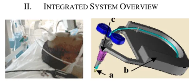
II. INTEGRATED SYSTEM OVERVIEW
Figure 1. Classic ICP sensor in use (left) and 3D model of the proposed wireless sensor (right)
Figure 1 presents a 3D model of the proposed wireless catheter-tip sensor. As can be shown, the system consists of four main components; a silicon pressure sensor, a capsule, a catheter tube and the interconnections. A piezoresistive pressure sensor has been implemented on a thin silicon
b a
membrane in order to convert the pressure into an electrical signal. A tiny polymer capsule is used in order to package the pressure sensor. A double side flex with embedded conductors has been used to create the interconnections between the pressure sensor and the control circuit which is further connected to a wireless transceiver (fig.1.b). A flexible polyamide has been used in order to fabricate the catheter tube through which the interconnections will go. Finally a new ergonomic package has been implemented in order to enclose the catheter, the control circuitry and the wireless transceiver. The catheter of the proposed system (fig.1.a) has a diameter of 3.5French (1.16mm) and a reduced length of only 200mm in comparison to a 1m length for the existing wired systems.
The proposed wireless catheter-tip sensor can be inserted easily through the cranial bone and meninges into the brain parenchyma in order to measuring the ICP. The main goal from the proposed system is twofold. First, in contrast with the existing wired sensors, the wireless capability of the proposed sensor enables the patient to move freely for any other medical inspections. Second, the usage of the biocompatible polymer (PEEK) in the fabrication of the cranial bolt (fig.1.c).
III. FABRICATION PROCESS FLOW
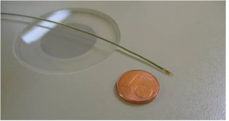
Figure 2. A finished piezoresistive pressure sensor after the passivation step.
As seen from figure 2, the proposed ICP sensor consists of an absolute piezoresistive pressure sensor[4,5] and an electrostatic actuator[6,7]. Two silicon electrodes have been used in order to implement the electrostatic actuator. The bulk silicon reassembles the bottom electrode and is used as a vacuum reference while the membrane itself has been used as the top electrode.
The pressure sensor has been implemented through the direct bonding between two wafers; a standard silicon substrate and an SOI wafer. Eight-mask process has been used in order to fabricate the sensor as shown in fig. 3 and involves direct-bonding and ion implantation techniques. The fabrication process starts with a standard 4”, n-type, (100) and 4-6.cm resistivity wafers. The first step is to grow a 2µm thick thermal silicon dioxide layer (fig.3.a) which defines the reference cavity depth. Then, the first mask is used in order to pattern a cavity with 300µm x 300µm dimensions through BHF wet etching (fig.3.b). Basically, the cavity pattern defines the dimensions of the pressure sensor’s membrane. Another oxide layer is then thermally grown over both the processed standard silicon substrate as well as the SOI wafer (n-type, (100) and 4-6.cm resistivity) in order to electrically isolate
the bottom and top electrodes that form the electrostatic actuator. Then, both wafers are direct bonded under vacuum (at least 4mbar
10 ) to create the pressure sensor’s reference cavity and electrostatic actuator(fig.3.c). The bulk of the SOI wafer is then etched using the KOH in order to release the membrane (fig.3.d). The main purpose from using the SOI wafer is to control accurately the membrane thickness which is fixed to be 5µm. The buried oxide layer of the SOI wafer is then wet etched using BHF. In order to access bulk which is the bottom electrode, Reactive ion etch has been used on the 5µm silicon layer followed by a BHF wet etching (fig.1.e). This is followed by growing a 50nm oxide layer(fig.3.f). Ion implantation is then used in order to create the strain gages (P), interconnection between gages (P++) and the contact zone of the membrane and the electrodes (N++)(fig.3.g). Next step is to open contact areas in silicon dioxide layer and this is followed by a deposition and patterning of 100nm/800nm titanium-gold layer (fig.3.h) to have a connection with the Wheatstone bridge, electrostatic actuator and temperature sensor. Then the fabricated structure is passivated using a 1µm thick SU-8 photoresist which is well known to be compliant with many levels of the iso 10993 biocompatibility standard [8,9]. Finally, the back side of the standard wafer is grinded and the final structure is diced. At this step, the pressure sensor is finished and is ready to be packaged as will be explained in the next section. The pressure sensor has dimension of 2000µm length, 690µm width and 200µm thick and the sensitivity is between 30-40µV/V/mmHg.
a b c d e f Pressure sensor Temperature sensor Electrostatic actuator contacts
Figure 3. fabrication process flow.
The direct bonding step is considered to be the most critical step in the proposed fabrication process. For a reliable bonding, wafers surfaces which have to be bonded must be well cleaned and activated [10, 11]. In order to remove all photoresist residuals, wafers are cleaned with Piranha solution (3:1 Sulfuric Acid: Hydrogen Peroxide) for 10 min and then they are rinsed in DI water and finally dried in N2 atmosphere. Besides, in order to improve the bonding energy, wafers are activated in RCA1 solution for 10 min followed by rinsing and drying in N2 as well. Then the wafers are initially direct bonded in a wafer bonder in vacuum at 200°C. Finally, the direct bonding step is completed by annealing the wafers at 1100°C for two hours under nitrogen flow.
The proposed pressure sensor is based on the well know silicon piezoresistive phenomena and makes use of the classic Wheatstone bridge concept. The sensitivity curve of the proposed sensor is presented in Fig.4. As can be seen, the relation between the applied pressure and the measured differential voltage is quite linear. Besides, the sensor features a sensitivity of around 35µm/V/mmHg for a range of 0-150mmHg.
Figure 4. The measured voltage versus the applied pressure for the proposed pressure sensor (Bridge’s voltage : 1,25V).
One important advantage of the proposed pressure sensor is the in-situ auto-calibration. This is done basically through applying a voltage between the electrostatic actuator’s
electrodes which results in a controlled membrane displacement. This displacement is further converted into a specific reference pressure which is controlled through the applied voltage. The basic operation of the auto-calibration process is shown in Fig. 5 where the reference pressure is controlled by the applied voltage.
Figure 5. The measured voltage signal and the corresponding pressure values versus time for a generated electrostatic pressure through applying a
square wave signal of 1.25Hz and 20V amplitude.
IV. CATHETER TIP PACKAGING
Figure 6. a detailed 3D model of a packaged pressure sensor indicating the sensor, flexible substrate and the interconnection.
Fig. 6 presents a 3D model of the proposed pressure sensor focusing on the catheter tip. As shown, the pressure sensor is mounted on the tip of a catheter in order to be inserted directly into intra parenchymental space. Thanks to the wireless transceiver, the catheter length is reduced to only 200mm. A double side flexible printed circuit board (PCB) with eight conductors has been used to create the interconnections between the control circuit on a side and the pressure sensor, an electrostatic actuator and a temperature sensor on the other side. The flexible PCB (fig.6.b) has four connexions on each side and has a 200mm length, 690µm width, 100 µm thick and 140 µm Conductors’ pitch. The four top conductors have been used to connect the Wheatstone bridge using wire bonding (ball or wedge bonding). Then, two bottom conductors have been used to connect the electrostatic actuator electrodes while the remaining two conductors are used to connect to the
Standard Si P region Si oxyde N region Ti/Au h g
a
b
d
c
e
passive temperature sensor. The mentioned bottom four connections have been realized with flip chip bonding based on Au studbumps and epoxy underfill [12]. The resistance of the Wire bonding, Flip Chip bonding and the total interconnection line is 142mmmrespectively.
The capsule (fig.6.c) which contains the pressure sensing element is fixed at the catheter tip using a biocompatible epoxy adhesive. The Capsule itself is made from biocompatible polymer (PEEK) while the Catheter (fig.6.a) is made from a biocompatible polyamide (PA11) tube with 195mm length, 0.8 mm inner diameter and 1.16mm outer diameter. Afterwards, the flexible PCB is inserted inside the catheter and the pressure sensing element (fig.6.d) is positioned inside capsule. Then, the sensing element as well as the capsule and the catheter are sealed with a biocompatible silicone adhesive (fig.6.e). Finally, at the other end of catheter, the flexible PCB is fixed and wire bonded to a classic PCB where the control circuit as well as the wireless transceiver is fixed inside a cranial bolt.
Figure 7. The catheter-tip packaging.
V. CONCLUSION
A new concept of self calibrating pressure sensor has been proposed and verified experimentally. The dynamic calibration capability of the proposed sensor makes it of great importance for biomedical implantable pressure sensors considering that the long term drift is being avoided. Besides, a catheter tip packaging which is compliant with the biocompatibility standard (iso 10993) has been fabricated and proved to be an enabling technology for the in-vivo evaluation. This work is being resumed through the development of embedded wireless transceiver as well as the
fabrication of a new cranial bolt in order to be used in ICP measurement.
ACKNOWLEDGMENT
This work has been supported by the French National Research Agency (Agence Nationale de la Recherche)
REFERENCES
[1] M Czosnyka, J D Pickard, “Monitoring and interpretation of intracranial pressure, “Journal of Neurology, Neurosurgery, and Psychiatry 2004;75:813-821;
[2] Brian North,“INTRACRANIAL PRESSURE MONITORING”, Head Injury, 1997, Chapman & Hall, Pages 209-216
[3] R Stendel, J Heidenreich, A Schilling, R Akhavan-Sigari, R Kurth, T Picht, T Pietilä, O Suess, C Kern, J Meisel, M Brock, “Clinical evaluation of a new intracranial pressure monitoring device”, Acta neurochirurgica,2003; 145(3):185-93.
[4] Yozo Kanda, “Piezoresistance effect of silicon”, Sensors and Actuators A: Physical, Volume 28, Issue 2, July 1991, Pages 83-91
[5] C.Maj, M.Olszacki, M.Al bahri, P.Pons, A.Napieralski, “Analytical method of strain gauge-based pressure sensor design “, EuroSimE 2008 [6] Yilmaz, M. Zervas, M. Erdem, A.B. Yalcinkaya, A.D. Leblebici, Y., “ Design and integration of a bimorph thermal microactuator with electrostatically actuated microtweezers”, Research in Microelectronics and Electronics, 2008. , June 22 2008-April 25 2008, pages: 125-128 [7] Sakata, M.; Komura, Y.; Seki, T.; Kobayashi, K.; Sano, K.; Horiike, S.;
“Micromachined relay which utilizes single crystal silicon electrostatic actuator”, MEMS '99, 17-21 Jan. 1999, Pages:21-24
[8] Geoffrey Kotzar, Mark Freas, Phillip Abel, Aaron Fleischman, Shuvo Roy, Christian Zorman, James M. Moran, Jeff Melzak, ”Evaluation of MEMS materials of construction for implantable medical devices ”, 2002, Biomaterials 23 ,pages: 2737-2750
[9] Gabriela Voskerician, Matthew S. Shive, Rebecca S. Shawgo, Horst von Recum, James M. Anderson, Michael J. Cima, Robert Langer, “Biocompatibility and biofouling of MEMS drug delivery devices”, 2003, Biomaterials 24, pages: 1959–1967
[10] Yongli Huang, A. Sanli Ergun, Edward Hæggström, Mohammed H. Badi, and B. T. Khuri-Yakub, “Fabricating Capacitive Micromachined UltrasonicTransducers With Wafer-Bonding Technology”, Journal of Microelectromechanical Systems, vol. 12, no. 2, april 2003, pages : 128-137
[11] Q.Y. Tong , U. Gosele , “Semiconductor Wafer Bonding: Science and Technology”,1998, John Wiley & Sons Inc, pages : 49-67
[12] Ph. Clot, J.-F. Zeberli, J.-M. Chenuz, F. Ferrando and D. Styblo, “Flip-Chip on Flex for 3D Packaging”, 1999 IEEVCPMT lnfl Electronics Manufacturing Technology Symposium
[13] John H. Lau, “Flip Chip Technologies”, 1995, McGraw-Hill Publishing Co, page: 136