Computer Science and Artificial Intelligence Laboratory Department of Electrical Engineering and Computer Science
Massachusetts Institute of Technology Cambridge, MA 02139
Concurrent Gate-Level Circuit Simulation
by
Jacinda R. Shelly
Submitted to the Department of Electrical Engineering and Computer Science in Partial Fulfillment of the Requirements for the Degree of
Master of Engineering in Electrical Engineering and Computer Science at the Massachusetts Institute of Technology
May 2010
Copyright 2010 Jacinda R. Shelly. All rights reserved.
MASSACHUSETTS INSTITUTE OF TECHNOLOGY
AUG 2 4 2010
LIBRARIES
ARCHIVES
The author hereby grants to M.I.T. permission to reproduce and
to distribute publicly paper and electronic copies of this thesis document in whole and in part in any medium now known or hereafter created.
Author Certified by Accepted by
121
Department of Electrial)
j
Ar
Engineering and Computer Science May 17, 2010
Dr. Christopher J. Terman Thesis Supervisor
\J ' Dr. Christopher J. Terman
Concurrent Gate-Level Circuit Simulation
byJacinda R. Shelly Submitted to the
Department of Electrical Engineering and Computer Science May 17, 2010
In Partial Fulfillment of the Requirements for the Degree of Master of Engineering in Electrical Engineering and Computer Science
Abstract
In the last several years, parallel computing on multicore processors has transformed from a niche discipline relegated primarily to scientific computing into a standard component of high-performance personal computers. At the same time, simulating processors prior to manufacture has become increasingly time-consuming due to the increasing number of gates on a single chip. However, writing parallel programs in a way that significantly improves performance can be a difficult task. In this thesis, I outline principles that must be considered when running good gate-level circuit simulations in parallel. I also analyze a test circuit's performance in order to
quantitatively demonstrate the benefit of considering these principles in advance of running simulations.
Thesis Supervisor: Dr. Christopher J. Terman Title: Senior Lecturer
Acknowledgements
I am extremely grateful to Chris Terman, my thesis supervisor. Throughout this experience, he has gone above and beyond the call of duty as an advisor and mentor. His constant faith in my
ability to complete this thesis meant that at least one of us was certain I would graduate. I would also like to thank Anne Hunter for showing a peripatetic transfer student the ropes. Without her help, my life as a student at MIT would have been far more difficult.
I am also grateful to my husband for providing encouragement and support to his frequently sleep-deprived wife.
My parents also deserve recognition as stellar examples of hard work and commitment. Without them, I would never have made it this far in life.
Finally, who would have thought the enterprise of a year would hinge on a bowl of soup? So, thanks to the soup.
Table of Contents
1 Introduction ...
8
1.1 Thesis Goals... 8
1.2 Outline...9
2 Background...
10
2.1 Circuit Simulation Levels... 10
2.2 Previous W ork...11
3 C ircuit Sim ulator O peration...
13
3.1 Sequential Gsim Overview ... 13
3.1.1 Class Organization... 13
3.1.2 The Netlist... 15
3.1.3 The Timing File... 15
3.1.4 Simulation Procedure... 16
3.2 Parallel Gsim Overview ... 16
3.2.1 Intel Threading Building Blocks (TBB)... 17
3.2.2 Using TBB's Lessons to Create an Intelligent pThreads Implementation ... 19
4 Principles for M apping Circuits to C ores...
22
4.1 Partitioning... 22
4.2 Dividing W ork Evenly... 24
4.3. Other Considerations... 26
4.4 Analysis ... 27
5
Experim ents ...
28
5.1 Base Case Circuit...28
5.1.1 Test File Demonstration... 29
5.1.2 How to Partition the Test Circuit ... 30
5.1.3 Partitioning vs. Parallelization Experiments... 31
6. D iscussion and Future W ork...
39
List of Figures
Figure 1: A five-stage pipelined pocessor with added dashed lines indicating a possible partiting scheme given an ideal multi-core system with large single-core caches (Source: 6.823 Fall 2009 L ecture 5 N otes)... ... 23
Figure 2. An example of a fan-in circuit composed of AND gates... 29 Figure 3. Truth table for an AND gate fan-in circuit of arbitrary size... 30 Figure 4. The effect of initialization cost on the performance of a simulation using a small test vector as the number of threads is increased. ... 31 Figure 5. The worst possible way devices in my test circuits could be assigned to threads. This arrangement maximizes the number of shared nodes... 32 Figure 6. The best possible way devices in my test circuit could be assigned to threads. This arrangement minimizes the number of shared nodes... 33 Figure 7. Normalized performance improvement as a ratio of the runtime for the threaded
version divided by the runtime of the serial version... 35 Figure 8. Performance improvement for larger, poorly partitioned circuits upon parallelization. 36 Figure 9. Performance gain caused by partitioning alone when running a parallel simulation. The y-axis is calculated by dividing the runtime when partitioned appropriately by the runtime when partitioned in the worst possible m anner. ... 37 Figure 10. The overall effect of parallelization and partitioning when compared with the serial, poorly partitioned case... 38
.4
1. Introduction
1.1 Thesis Goals
In the last several years, parallel computing on multicore processors has transformed from being a niche discipline relegated primarily to scientific computing into a standard component of high-performance personal computers. As processors become more complex, it becomes increasingly important to use simulations to detect design flaws before processors and other computer
hardware are fabricated. It is important to discover these flaws in simulation prior to fabrication because of the expense involved in actually producing a chip. These simulations occur at many different levels of design, ranging from transistor-level simulations involving voltages and currents, to system integration simulations. At every level, these simulations are computationally expensive and time-consuming, so efforts to improve performance of simulations are of great importance.
While there has been a great deal of research on simulation algorithms at low levels, there has been less research done on parallelizing gate-level simulation. Gate-level simulation is of particular interest since that's the highest level of simulation that can be used to verify the coverage of the manufacturing tests used to determine if a chip has been fabricated correctly.
Lower-level simulations provide unnecessary detail; higher-level tests abstract away many of the circuit structures and hence don't provide information on how defects in a particular structure would affect what is observed at the pins.
In this thesis, I outline principles based on machine-level features that must be considered in order to achieve real-time speed-up when running simulations on multi-core machines. This
involves assigning the simulation of subcircuits to specific cores with the goal of maximizing parallelism by minimizing inter-core communication.
1.2 Outline
Section 2 covers background relevant to the topic of circuit simulation. I provide a brief guide to the properties of the four primary levels of circuit simulation. I also outline previous research conducted on concurrent gate-level circuit simulation. Section 3 covers the operation of the specific simulator that I used and the modifications that were made to this simulator in order to allow it to run on multiple cores.
Section 4 outlines general principles that need to be considered when running simulations in parallel. These general principles provide a useful checklist for anyone considering
implementing parallel circuit simulation specifically, but these principles can also be generalized to the parallel implementation of many different programs.
Section 5 describes the experiments I conducted running circuit simulations are circuits partitioned differently for different threads, and Section 6 discusses the implications of these results. My seventh and final section summarizes the contributions of my research as a whole.
2. Background
2.1 Circuit Simulation Levels
Circuit simulation can be conducted at a number of different levels depending on the specific information a tester wishes to obtain from the simulation. In order of decreasing complexity and increasing size of the circuit primitives, these levels are the circuit, switch, gate and
functional/behavioral levels. I outline briefly the different levels below. The simulator I used in this research was a gate-level simulator whose design is outlined in the next section.
2.1.1 Circuit Level
The circuit level is the lowest level of simulation possible. It simulates a circuit based on the underlying physical principles of the circuit's most basic primitives - resistors, transistors, capacitors, wires, etc. Circuit level simulations are the most accurate type of simulation, but are impractical for circuits larger than several thousand transistors because of the length of time they take to run [1].
2.1.2 Switch Level
Switch-level simulations are the next highest level and treat MOSFET switches and transistors as the primitive devices. This allows larger circuits to be modeled within a reasonable period of time.
2.1.3 Gate Level
Gate-level simulation is similar to switch-level simulation except that the primitive unit is a logic gate rather than a MOSFET switch. Collectively, switch-level and gate-level simulations are
known as logic-level simulations.
2.1.4 Functional/Behavioral Level
Functional- and behavioral-level simulators analyze circuits at the highest level by grouping segments of the circuit into functional units. This level of simulation allows ease of modification and produces rapid results, but cannot easily detect many low-level faults caused by defects in manufacturing. Because the purpose of my research is to improve the speed of evaluating
whether tests can detect all or most of the possible manufacturing flaws, I cannot use this level of abstraction as it is unlikely to have a high enough resolution to detect a majority of flaws.
2.2
Previous Work
Using parallel processing to improve the performance of simulations has been of interest for over two decades, but the primary work has been conducted using switch-level simulations. Initial attempts to measure available parallelism in switch-level simulations by Bailey and Snyder found that the typical activity level of devices was below 3% [2]. However, parallelism research continued with the advent of asynchronous parallel execution constrained by critical path
analysis as discussed in Briner et al [3]. They were able to show significant improvements in performance running their simulations on multiple processors with random partitioning compared to running the simulations serially, although they concluded that their methods still failed to take full advantage of available parallelism and that their methods performed poorly on circuits with low inherent parallelism (as would be expected).
where they compared different parallel protocols and found improvements in performance of between 3 to 6 times for simulations running on 8 processors using the highest performing parallel protocols [4]. These results are promising with regard to applying similar techniques at the gate level.
Work that has specifically been performed at the gate level includes studies by include Sporrer et al. who obtained speedups of about 8 when using 20 workstations in a cluster to perform gate-level simulation using a Time Warp synchronization technique [4, 5]. Since high computation granularity is critical for parallel simulation, Wisley and McBrayer investigated ways to combine processes in order to increase computation granularity [6]. While there have been some more recent studies on concurrent gate-level simulation, there have been very few that focused
specifically on fault simulation and ways to combine parallelism available in the circuit simulation itself, as well as parallelism available by virtue of the fact that many similar simulations with small variations are being run to see whether faults can be detected.
3. Circuit Simulator Operation
For my simulations, I used a gate-level circuit simulator known as gsim designed by Christopher Terman. In this section I describe the original sequential gsim implementation as well as the
steps we took in attempting to create a version that could run in parallel.
3.1 Sequential Gsim Overview
Gsim is an event driven gate-level circuit simulator written in C++ which takes as input two files
- a netlist file and a timing and testing file. Gsim runs the series of tests listed in the timing file and outputs whether it detected any mismatches between the predicted and observed signal values as well as other useful information about the system such as the numbers of nodes and devices in the circuit and the number of evaluations and updates that occurred.
3.1.1 Class Organization
Gsim possesses three classes that embody the functionality of the circuit being simulated. These are the network, node and device class. The data members and functions comprising these classes are summarized in the following three tables.
The Node Class
Data Members Functions
name The node's name adddriver Appends a new device to
the node's list of drivers
*network The network this node is a add_fanout Appends a new device to
member of the node's list of fanouts
drivers The devices that have this node reset Resets the value of the node
as an output at the beginning of a
simulation
danouts The devices that have this node schedule-update Prepares a node to be
as an input updated at the end of a time
step if its value has changed
value The node's current value update Performs an update by
setting value to nextvalue,
and scheduling all fanout devices to be evaluated at
the next timestep
nextvalue The node's value after its next setinput Sets the input of a node to a
update specific value and adds that
node to the update list
input Indicates whether the input has get-name Returns the value of name
been set by the timing file
scheduled Indicates whether the node is get-value Returns the value of value
scheduled to be updated
The Device Class and LogicGate Child Class
Data Members Functions
name The device's name finalize Schedules a device for evaluation
once the network is finalized
*network The network this device is a reset Resets the device's internal state
member of
**inputs Nodes that are inputs to this evaluate Computes new values for outputs
device based on inputs
* *outputs Nodes that are outputs of this tristate Returns whether this device can
device produce tristate output
ninputs The number of inputs and
noutputs outputs possessed by the device
scheduled Indicates whether the device is
The Network Class
Data Members Functions
node-map Maps a string node name to a findnode Checks whether a node is
pointer to that node contained in nodemap and
if its not, creates the new node.
nodes A list of all the nodes in the adddevice Adds a device to the
network network by adding it to
devices
devices A list of all the devices in the finalize After all nodes and devices
network have been added, performs
any necessary adjustments and sets finalized to true
update A list of nodes scheduled to be reset Resets the network
updated
eval A list of devices scheduled to be schedule-update Adds a node/device to
evaluated schedule eval update or eval, respectively
finalized Boolean indicating whether this simstep Performs a unit-delay
network has been finalized simulation on the network. Described in full detail in
____ ____ ____ 3.1.4.
time The current simulation time dump Print out various attributes
stats of the network in
human-readable form
nevals Counts of the number of
nupdates evaluations, updates, iterations
niterations and steps which have occurred
nsteps in the simulation
3.1.2 The Netlist
A netlist in gsim is a list of all devices and their associated inputs and outputs, with each device on a separate line. Gsimi supports standard logic gates, muxes, adders, tri-state logic, latches, registers and multi-port memories.
3.1.3 The Timing and Testing File
The timing and testing file contains the specifications for simulations that the user wants run on a specific circuit as defined by the corresponding netlist. Using this file, the user can specify
which nodes are connected to specific pins, group nodes to be asserted together by a timing statement, print messages to stdout, control the clock rate of the circuit and the length of setup and hold times. Following these setup parameters, the bulk of the timing file consists of
statements that set nodes to particular values at particular times, followed by the expected output given those inputs
3.1.4 Simulation Procedure
The simulation of each clock cycle is split into a sequence of simulator actions: asserting input and clock values, running the simulation, testing outputs. Gsim calls the network's sim-step procedure at appropriate points in the simulation sequence. While the current simulation time is less than the specified stop time, sim-step alternates between performing scheduled updates (recomputing a device's output values from its current input values, scheduling changed nodes for eval) and evals (updating nodes with their new values, scheduling fanout devices for update).
At any given step, devices updates can be performed concurrently, as can the subsequent evals.
At any point during this process, if there are no scheduled evals or updates, then the simulation is finished and we can end that loop and move to the next test until all tests in the timing file are complete.
3.2 Parallel Gsim Overview
In any given iteration of gsim, a set of evaluations or updates can be performed concurrently. In the original program, these two operations were implemented asfor loops that either updated all the nodes on the update list or evaluated all the nodes on the eval list. Allowing these operations to run in parallel was the critical task for our code, and we attempted to parallelize this portion in
a variety of ways before finding one that consistently provided speedup when run in parallel.
We first attempted to use Intel's Threading Building Blocks (TBB) library before switching to pthreads to implement our parallel version of gsim. The specific methods we used and our experiences with each are outlined in the following sections.
3.2.1 Intel Threading Building Blocks (TBB)
Intel Threading Building Blocks (TBB) is a C++ library designed to allow non-threading experts to more easily introduce parallelism into their code. It works by abstracting away the specific threading mechanisms by introducing higher level functions and containers like parallel-for and
concurrentvector. I attempted to use TBB to parallelize gsim using the methods described in
the next three sections. Though each of these methods failed, the reasons why each method failed shed light on the challenges of parallelism specific to circuit simulation.
3.2.1.1 The Simplest Approach
Initially, I used TBB to change the code in the simplest way possible to see how well an unsophisticated approach might do. I modified the update and eval lists to use TBB's
concurrentvector data structure instead of the STL's vector. The primary reason for this was because concurrentvector supported concurrent calls to push-back. In terms of the functions
used, I modified the update and eval for loops to run as parallel
for
functions.This approach did not work. In fact, it increased the runtime of some circuit simulations by a factor of twenty or more - the opposite of the desired result. The primary reason for this was the
concurrentvector data structure. Using concurrentvector meant that each time a node or device was updated or evaluated and memory needed to be written, a lock was acquired on the
entire concurrentvector data structure. Since our operations take very little time compared to
1/0 operations and system calls, most nodes and devices were simply waiting for their turn to write memory. Therefore, the ultimate effect was of code that was still running sequentially because of the locks, but which was burdened by a gross amount of overhead. The next step was to try a different data structure.
3.2.1.2 A Better Version
In my second attempt at parallelization I removed the use of a concurrentvector in order to eliminate any possibility that this container was using locks that would inefficiently constrain updates and evaluations. This did not have the required effect because although locks were removed, nodes and devices could now be added to the update and evaluate lists multiple times, which meant that on the next time step more updates and evaluates would occur than necessary. More importantly, this implementation did not eliminate the root cause of the slowdown - writes to shared memory that required system calls to ensure cache coherency. In particular, the fact that entire nodes and devices were being added to the update and eval vectors caused larger writes to shared memory that significantly increased the runtime such that a "parallel" implementation could take up to 6 times longer than the serial version - clearly not what is desired from a parallel application.
3.2.1.3 Lessons from TBB
operation locality on a particular core over time is not important, I was not able to use TBB in a way that would improve performance.
The primary reasons for this are as follows. First, the overhead of TBB's high level functions was large compared to the number of evals and updates we would perform during a single operation. Second, there was no way to map individual nodes and devices to specific cores which would prevent shared writes, a major time sink, without working at a much lower level -at which point TBB has no advantage over pthreads. This prevented us from taking advantage of circuit locality.
3.2.2 Using TBB's Lessons to Create an Intelligent pthreads Implementation
Armed with experience from TBB, the next step was to create a pthreads implementation where we could control thread distribution to cores at a low level. The idea is that each thread is assigned a portion of the nodes and devices contained in a circuit. It then updates or evaluates the nodes and devices assigned to it on each iteration.
In order to prevent a single thread from getting "out of step" with the other threads, some type of barrier is necessary to synchronize the activity of the different threads. We initially tried using the built-in pthread barrier, but ended up needing to implement a custom barrier.
In pthreads, the standard barrier implementation initializes a barrier with attributes specified by the user which include the number of threads which need to call pthread-barrierwait before the program can continue. When pthreadbarrierwait is called, it increments a shared variable
which contains the number of threads that are currently waiting. When the number is equal to the number specified at initialization, the program can proceed.
The problem with this implementation for our purposes is that the barrierwait call requires a system call to check the value of count every time a thread checks in. It also writes to shared memory, thereby invoking the system's cache coherence protocol. Both of these operations are extremely costly compared to the amount of time a single thread spends updating or evaluating objects. If the update and eval operations were more costly, barrierwait might not be a bottleneck, but when compared with operations that take only microseconds to run, any system calls or writes to shared memory are significant bottlenecks. In addition, barrierwait must be called hundreds of thousands of times total in our test circuits - and real circuits and test files are much larger - which further decreases performance.
The answer, then, is to create an implementation of a barrier that does not rely on writing to shared memory. Instead, the custom barrier we use works such that each thread possesses an individual count of how many times it has reached the barrier and increments this count when it
calls barrierwait. It then reads every other thread's count of how many times it has reached barrierwait. Threads are able to proceed when every other thread has reached the barrier.
The advantage of this implementation is that no shared writes occur. Every thread writes to its own location and then performs a read of the values belonging to other threads. Shared reads are significantly less costly than shared writes.
After implementing this distributed barrier, we finally achieved a real-time performance gain when using a parallel version of gsim as compared to a sequential version. There were no further barriers in the implementation itself, but a good algorithmic implementation that minimizes shared writes is not enough to maximize performance. To do that requires more careful implementation of which parts of a circuit should be mapped to different threads in order to minimize shared writes and inter-core communication; i.e. how the circuit should be partitioned. This is the subject of the remainder of the thesis.
4. Principles for Mapping Circuits to Cores
In the previous section I demonstrated that writing parallel programs can be a complex process. In order to produce any speedup whatsoever it was necessary to eliminate as many system calls and shared writes as possible in the code- itself. This applies generically to any parallel
application. In our situation, the shared writes and kernel calls used by the standard pthreads barrier implementation were too expensive, so it was necessary to write a different barrier implementation. This eliminated shared writes caused by thread coordination, but in a circuit simulation there is another source of shared writes - connections between nodes and devices.
It is not enough to simply cut the circuit into arbitrary pieces and throw those pieces onto as many cores as you have available. This will lead to suboptimal performance. Instead, the following general principles should be followed to maximize potential speedup. The most important of these is partitioning such that communication between cores is minimized. Less important, but still useful considerations include dividing the work evenly, taking into account the size of a partition versus the memory of a processor and ensuring that sufficient tests are being run on the circuit (this consideration is usually not a problem in complex circuits).
Each of these considerations is discussed in this section. In the next section, I present empirical results demonstrating how these principles can be applied in practice.
4.1 Partitioning
To begin with, assume that the circuit to be analyzed is bigger than the cache of a single core, because if the entire circuit can fit in the memory of a single core, there is no need to run this
circuit on multiple cores. Doing so would simply create a large amount of unnecessary inter-core communication, causing slowdown. There may be some exceptions to this where the cost of communication is extremely low, as might be the case for two portions of a circuit that only communicated via a few wires but otherwise did not communicate.
However, if the circuit will not fit in a single core's memory, then some speedup might be
obtained through partitioning. Ideal partitioning attempts to divide the circuit between cores in a way that maximizes the independence of each subcircuit -which usually involves cutting
through a minimum number of nodes. Put another way, we are attempting to separate portions of the circuit that are already mostly independent. A concrete example of where this might occur would be dividing a pipelined processor along pipeline divisions. Since each pipeline stage is supposed to operate independently, this is a useful heuristic for separation.
I
_IBSrc | 'BIc MD1 i MDJ5 II
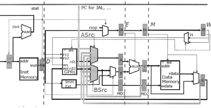
Figure 1: A five-stage pipelined processor with added dashed lines to indicate a possible partitioning scheme given an ideal multi-core system with large single-core caches (Source:
Partitioning in this fashion attempts to minimize the number of nodes that will need to be in shared memory. This example further assumes that each pipeline stage can fit in a single core's memory. This is not likely to be the truth in practice and it would be necessary to further subdivide the circuit using similar principles.
Many algorithms to statically partition circuits have been developed. A selection of these is described in Section 2.
4.2 Dividing Work Evenly
Suppose that in the circuit above (as is likely to be true) the Instruction Fetch stage will have very few operations on every iteration, while the register file and ALU stages are likely to have many evals and updates to perform. If the circuit is partitioned as in Figure 1, then the core processing the Instruction Fetch portion of the circuit will have long periods where it is idle while it waits for other stages to reach the barrier.
If the Instruction Fetch stage is small enough to be combined with another partition while still having both of them fit in a single core's memory, then combining these two is the simplest solution. In general, if two partitions can be combined to both fit on a single core, it is usually better to move put both of these on the same core - especially if neither of them is the bottleneck partition with respect to workload per iteration.
However, there may be no way to combine partitions easily. In this case, optimizing against the bottleneck problem is more difficult. On the one hand, we could assign the Instruction Fetch
stage to the same core as another partition. If this combination exceeds the memory of that core, we might see thrashing, which would increase the time spent by that core performing I/O instead of useful work. If this is still less than the time the core with the largest workload takes on each iteration, this might be a good solution.
Another option might be splitting up the bottleneck partition across more cores so that its average workload of evals and updates per iteration is smaller. We would want to apply good partitioning principles to this split to minimize the amount of communication between the two cores that are replacing the single partition. This might be an easy problem to solve, if the partition is easily divided into sub-partitions. If the partition is not easily divided, it will be necessary to balance the decrease in the workload of each processor per iteration against the increased latency that might be caused by inter-core communication.
It is difficult to predict exactly what the effect of any of these actions might be in advance, so in cases where there is heavy skew in workload, dynamic analysis, where different assignment schemes are tried and run on the good simulator might be the best option. The assignment scheme that provides the best performance for the good machine simulations can then be used for the potentially more extensive tests needed on a fault simulator. Another option is to dynamically meter the simulation as it is running and update the partitioning accordingly. This could potentially be accomplished by monitoring the number of cycles being used by other cores on each simstep and having less-burdened cores claim some nodes and devices, or by looking at the number of evals and updates being performed by a core on each simstep.
There is much room for exploration of dynamic analysis, but I do not explore it in this thesis as the circuits I ran experiments were primarily chosen to explore issues of static partitioning and to have a fairly equal workload across threads.
4.3. Other Considerations
Though minimization of communication through intelligent partitioning and analysis of
workload are the two primary considerations for maximizing the performance of a parallel circuit analysis application, there are a few other issues that should be considered in certain cases. These include using a sufficiently large test vector to offset initialization effects and being careful about attempting to use all available cores on a system as the scheduler may make this tricky.
4.3.1 Timing and Test File
The timing file should contain a large enough test vector that simply initializing the circuit in memory does not overshadow any other operations. For example, even an intelligently
partitioned circuit with a small test vector will show no speedup when compared with a parallel implementation because the time spent loading the nodes and devices into memory on the first test will dominate the performance. The increased speed of the remaining few tests due to caching will not be apparent.
This is a consideration for the simple fan-in circuit used as a test circuit in my experiments described in Chapter 5. There are only 4 distinguishable test cases, but these tests must be repeated several thousand times in order to cause the memory load factor to be small relative to
the effects of parallelization.
4.3.2 Threads Equal to the Number of Available Cores
On many multicore systems, the scheduler may limit the programmer's ability to use all of the available cores simultaneously, so maximal theoretical speedup may be constrained by this. For example, on our 8-core machine, the scheduler will not always utilize all 8 cores if 8 threads are used in the application.
4.4 Analysis
By exploring the general principles outline above it becomes clear that mapping circuits to cores for parallel processing requires consideration of the number of cores available, their
communication methods and the latency of different operations like reads and writes. In addition, the specific layout of the circuit being considered must be analyzed. A circuit which has an equal workload across all nodes and devices is easier to partition than one with a
relatively skewed load, where shared write considerations must be balanced against leaving some cores idle for a period of time on every iteration. In addition, things tangential to the actual program like the size of the test vector and the behavior of the computer's scheduler need to be taken into account.
Good analysis can increase performance significantly but, like creating parallel algorithms, is more complex than it appears at first glance.
5.
Experiments
In the previous section, I presented a selection of principles that need to be followed in order to maximize performance gains when running circuit simulations in parallel. In this section I present experiments that demonstrate each of the principles outlined in the previous section.
These experiments were conducted on an machine with 4 Intel dual-core Xeon processors, meaning that the theoretical maximum number of threads we could run would be eight, although as outline in Section 4.3.2, actually using eight threads does not produce as much of a
performance improvement as might be expected.
5.1 Base Case Circuit
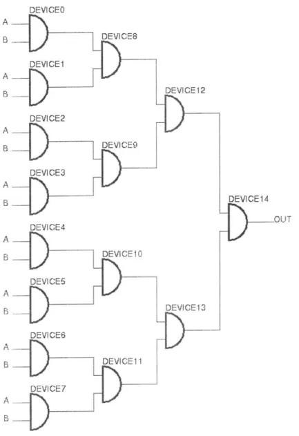
In order to conduct controlled experiments, and obtain the maximum possible gain from running the simulation in parallel, I began by reducing the problem to a trivially parallel circuit - a fan-in of AND gates. NOR, XOR, NAND or other gates would have worked equally well.
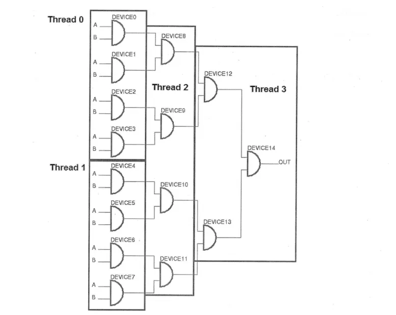
This circuit begins with 2" gates, which feed into a second level of 2"- gates. This recursive descent continues until a single gate is reached, at which point the circuit terminates in an OUT node. While being simulated, every node and device is visited as values propagate through the circuit. An example of this circuit with 23 devices at the start is shown in Figure 2.
I used a Python script to generate netlists for this type of circuit automatically, so I could quickly create a circuit of arbitrary size. I then ran experiments that demonstrate each of the principles
mentioned in Section 4.
5.1.1 Test File Demonstration
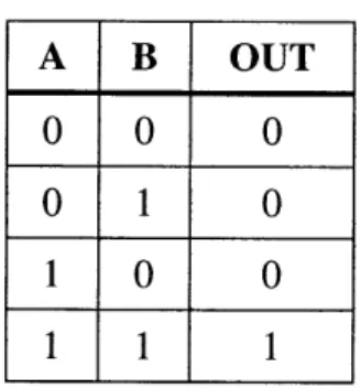
At the first input level, every device has the same two inputs. This results in four possible test cases corresponding to Figure 3, an AND gate's standard truth table.
A B OUT
0 0
0
0
1
0
1 0 0
1 1 1
Figure 3. Truth table for an AND gate fan-in circuit of arbitrary size.
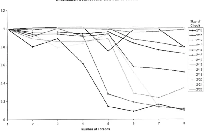
Since there are only four possible outcomes, in the test circuit each test is run 10,000 times to diminish the effect of initialization. If only four tests are used, cached values are used only three fourths of the time, so any potential performance improvement is overshadowed by initialization
costs. In fact, performance decreases as the number of threads increases. Figure 3 demonstrates this for circuits ranging in size from 29 to 222 initial inputs. A test I ran with only four tests demonstrated this, and can be seen in Figure 3. As mentioned in Section 4.3.1, the way to
counteract this is to run the same tests repeatedly. When conducting simulations for this specific circuit, I used 10,000 simulations for each test case.
5.1.2 How to Partition the Test Circuit
The benefit of using a simple fan-in circuit such as the one presented above is that it makes analysis much simpler. We know that a good partition minimizes the number of shared writes
-in the case of this circuit, that means m-inimiz-ing the number of nodes that are shared between cores.
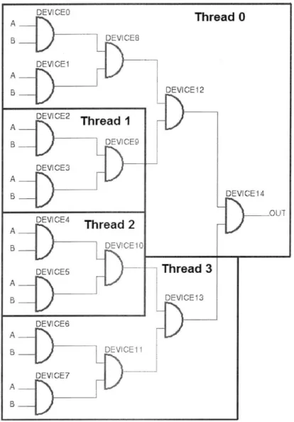
From this observation, it is easy to see the best and worst ways that devices might be assigned to cores in my fan-in test circuits. Using four threads as an example, Figure 5 shows the worst possible way devices could be assigned and Figure 6 demonstrates the best possible way. The
Python script that generated the original netlists ordered them in a way that resulted in the worst possible thread assignment.
Initialization Cost for AND Gate Fan-in Circuits
1.2 1 0.8 0 0.6 0.4 0.2 0 Size of Circuit -.- 2^10 2^12 -- 2A13 -ik--2A14 -2^16 --- 218 2^19 2A20 2^21 2^22 2 3 4 5 6 7 8 Number of Threads
Figure 4. The effect of initialization cost on the performance of a simulation using a small test vector as the number of threads is increased.
5.1.3 Partitioning vs. Parallelization Experiments
Since it is easy to determine the ideal partitioning scheme for the test circuit, it was also possible to design a program that would take a netlist as it was originally generated (with worst-possible thread assignment order) and transform the netlist into an ordering that would result in near-ideal thread assignment when used as input to gsim.
Thread 0 Thread I DEVICE4 A B DEVICE10 DEVICE5 BDEVICE13 DEVICE6 A.. BDEVICE11 DEVICE7 A B F
Figure 5. The worst possible way devices in my test circuits could be assigned to threads. This arrangement maximizes the number of shared nodes.
In addition, the simplicity of this circuit enable me to construct an experiment so that I could quantitatively determine how much performance can be gained by using effective partitioning apart from the effects of parallelization alone.
To accomplish this, I ran simulations which ran with 1, 2, 4 or 8 threads on circuits ranging in size from a single AND gate (with some control logic) up to circuits with up to 220 input devices. I ran these simulations first on circuits which were partitioned in the worst possible manner, then
on netlists which were reordered to be near-optimally partitioned for the number of threads being run.
Figure 6. The best possible way devices in my test circuit could be assigned to threads. This arrangement minimizes the number of shared nodes.
By comparing the results of these tests, I was able to determine quantitatively the maximum amount that partitioning can improve the runtime performance of a simulation as compared with a circuit whose only difference is that it is poorly partitioned.
Experiment 1: Performance Improvement due to the addition of cores alone
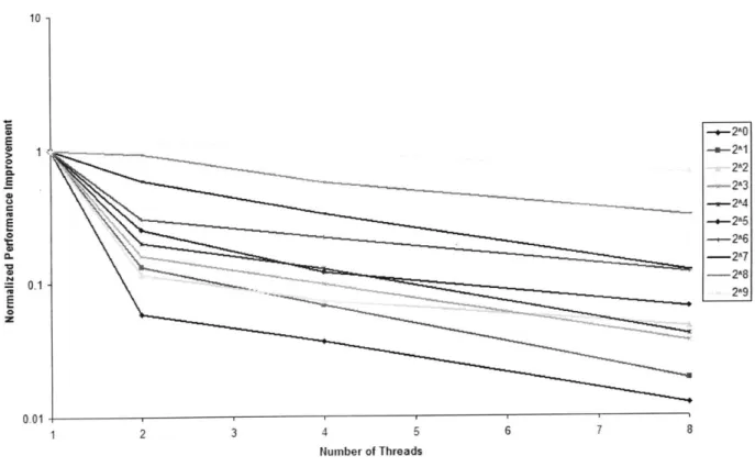
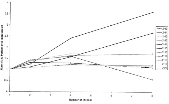
In my first experiment, I analyzed whether any performance improvement could be achieved in the presence of poor partitioning simply by increasing the number of threads used. Based on my Chapter 4 analysis, I expected the answer would depend on the circuit size as compared with the cache size. Figures 7 and 8 demonstrate the results of this experiment, where it is possible to see a fairly sharp cutoff at circuits of size 210 where the benefit of using multiple cores begins to outweigh the cost of inter-core communication. At this point, performance improvement caused by minimizing cache thrashing begins to outweigh the detrimental effects of inter-core
communication.
Figure 7 by demonstrates that if an entire circuit below a certain size can fit within the cache, there is no benefit to adding cores because it adds communication costs without providing any additional caching benefits (and in fact, subtracting from previously useful caching). In the worst, case, using 8 threads on very small circuits decreased performance by up to 8000%.
Figure 8 shows how as the circuit size begins to exceed the size of the cache, adding more cores does begin to provide some benefit. In fact, if we concentrate specifically on the 2" circuit, we can see the threshold. For this size circuit, adding a second core improved performance by 50%, and using four cores provided approximately the same performance, but using eight cores caused a severe downswing in performance as communication costs became too costly once the circuit was split across more cores and caches than necessary.
Normalized Runtimes for Worst-Case Partitioning of Small Circuits (<2000 Nodes+Devices)
2 3 4 5 6 7
Number of Threads
Figure 7. Normalized performance improvement as a ratio of the runtime for the threaded version divided by the runtime of the serial version.
was maximized for a circuit of the size 2"4, after which performance does not improve as much compared to the serial case for increasing circuit size. This is likely because the size of the subcircuit assigned to each thread again begins to exceed the cache size of an individual core.
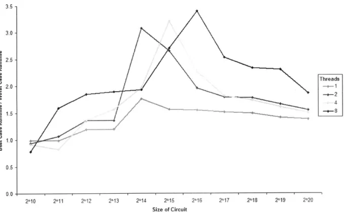
Experiment 2: Determining the effect of partitioning alone
The second part of the experiment was to determine the effect partitioning would have on performance separately from increasing the number of cores used. To do this, I recorded the runtime of simulations for circuits that were partitioned in the worst possible way versus circuits that were partitioned appropriately for the number of threads available. I also tried partitioning a single-threaded simulation as though it were running on two cores to see whether that might have
10 E a. CL 'a 0.1 0-0 --. 2A0 -u-2^0 2^2 ~2A6 _u~2A7 -29
an effect.
Normalized Runtime for Worst-Case Partitioning of Large Circuits (>2000 Nodes+Devices)
s2-70 1,5-221 -+-210 -+2A14 -+-2A16 2^18 2119 2420 1 2 3 4 5 6 7 8 Number of Threads
Figure 8. Performance improvement for larger poorly partitioned circuits upon parallelization.
Figure 9 shows the results of this experiment as run for circuits above the level where the advantages of parallelization begin to outweigh the disadvantages of increased communication. Even for a single-thread, proper partitioning seems to improve performance slightly, possibly because of an improved access pattern when caching, but I did not fully investigate this because of time constraints.
More significantly, we can see that a sweet spot exists where effective partitioning causes a sharp increase in the efficiency of the simulation. This is the point at which the size of the subcircuit is
very close to the cache size and maximal benefit is achieved from having each processor make as few writes to shared memory as possible by minimizing the number of nodes and devices that need to be shared with each core. After this maximally efficient point, the size of the subcircuits begins to exceed the size of single-core caches enough that the performance improvement is less
significant.
Effect of Partitioning Alone on Simulation Performance
3.5 - 30-E to -Threads 1
2A10 2A11 2A12 2^13 2A14 2^15 2A16 2A17 2A18 2A19 2^20
Size of Circuit
Figure 9. The performance gain caused by partitioning alone when running a parallel
simulation. The y-axis is calculated by dividing the runtime when partitioned appropriately by the runtime when partitioned in the worst possible manner
Strikingly, it is possible to see how closely this effect is connected to the size of the circuit by noticing that the circuit size where maximal performance improvement due to partitioning is achieved doubles as the number of threads doubles. This presents very strong support for my explanation.
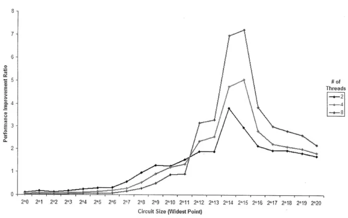
Experiment 3: The Total Effect of Parallelization and Partitioning
After running experiments to separate out effects of the two potential speedup methods, I compared the results to analyze the overall effect by looking at the ratio of a partitioned, parallel simulation with a single-threaded, worst-case partitioned circuit. This is shown in Figure 10.
The results displayed in Figure 10 are the product of the two ratios calculated above, i.e.: Overall Performance Ratio = Partitioning PR x Parallelization PR
Thus, maximal overall performance improvement is achieved by maximizing the product of these two performance ratios.
Combined Effect of Parallelization and Partitioning
7-6 -# of E \Threads E 3 -2 1-
0-2^0 2^1 22 2A3 2^4 2^5 26 2^7 2^8 2^9 2^10 2^11 2^12 2^13 2^14 2^15 2A16 2A17 2^18 219 2^20 Circuit Size (Widest Point)
Figure 10. The overall effect ofparallelization and partitioning when compared with the serial, poorly partitioned case.
6. Discussion and Future Work
The results presented in this thesis break down the complicated problem of how to separate the relative effects of partitioning and parallelization by reducing the problem to an extremely simple circuit that can be analyzed without complicated algorithms. This approach allowed me to quantify the validity of principles asserted in Chapter 4.
In the real world, consideration of the factors mentioned in Chapter 4 should be conducted before full-scale simulation begins, especially if simulation performance is particularly important. Of the simulation aspects mentioned in that chapter, the most important ones in the real world are likely to be how many cores to use for simulation and finding the optimal way to partition the circuit either statically or dynamically. As a minor note, in real world simulations,
considerations involving whether a circuit is too small to need partitioning are unlikely to be relevant.
Future work in this area will involve analysis of the relative performance of various partitioning algorithms on different, more complex types of circuits, since most circuits in the wild do not contain the kind of regularity I took advantage of in my test circuit. As mentioned in the background section, some work in this area has already been conducted at the switch level by Chen et al [4].
Fault simulation, another area where further investigation would be useful. One logical way to extend this research to fault simulation is to first find the ideal number of cores and partitioning for a good circuit simulation, then replicate that across multiple cores using map-reduce or a
similar algorithm. For example, if the ideal number of cores to use to perform a good simulation of a circuit is 8, and a particular machine has 64 available cores, a master could assign groups of 8 cores subsets of the test vector. In order to make this more efficient, if different individual tests demonstrate different usage across the circuit, it might be possible to cluster tests such that usage is maximized.
Dynamic partitioning, as mentioned earlier, is also an interesting area for further exploration. In trying to predict the future from events of the past, this type of research may benefit from
7. Contributions
In this thesis, I explored how to extract maximal performance improvement from a gate-level circuit simulator when run in parallel. My primary contributions are as follows:
e Outlining general principles that should be considered when attempting to parallelize
circuit simulations
e Implementing several versions of the gsim simulator using Intel@ Threading Building
Blocks
e Analyzing a bootstrap-level- circuit to quantify the maximal performance improvement
that could be achieved through parallelization and effective partitioning
The analysis conducted in this thesis is a proof-of-concept that a high level of performance improvement can be achieved in circuit simulation if portions of the circuit are independent enough to be effectively partitioned, and if the resulting partitions are of an appropriate size such that a single core can take advantage of the partition locality.
References
[1] S. M. Rubin, Computer Aids for VLSI Design. Addison-Wesley Publishing Company, 1994, Ch. 6.
[2] M. L. Bailey, "An Empirical Study of On-Chip Parallelism," in Proceedings of the 2 5th
ACM/IEEE Design Automation Conference, p. 160-165, Jun. 1988.
[3] J.V Briner. "Taking Advantage of Optimal On-Chip Parallelism for Parallel Discrete-Event Simulation," IEEE International Conference on Computer-Aided Design, ICCAD-88, p.
312-315, 1988.
[4] Y. A. Chen, J. Vikas and R. A. Bagrodia. "A Multidimensional Study on Parallel Switch-Level Circuit Simulation," 1 1th Workshop on Parallel and Distributed Simulation, pp. 46, 1997. [5] C. Sporrer and H. Bauer. "Corolla partitioning for distributed logic simulation of
VLSI-circuits," Proceeding of the Seventh Workshop on Parallel and Distributed Simulation, p. 85-92, 1993.
[6] McBrayer, T. J. Wilsey, P.A. "Process combination to increase event granularity in parallel logic simulation," 9th International Parallel Processing Symposium, pp. 572, 1995.