HAL Id: hal-02269412
https://hal.archives-ouvertes.fr/hal-02269412
Submitted on 22 Aug 2019HAL is a multi-disciplinary open access archive for the deposit and dissemination of sci-entific research documents, whether they are pub-lished or not. The documents may come from teaching and research institutions in France or abroad, or from public or private research centers.
L’archive ouverte pluridisciplinaire HAL, est destinée au dépôt et à la diffusion de documents scientifiques de niveau recherche, publiés ou non, émanant des établissements d’enseignement et de recherche français ou étrangers, des laboratoires publics ou privés.
Matlab/Simulink functional tests with STB/AGATHA
tool
J. Pierron, A. Lapitre, J Gallois, S Devulder, T Gueguen, P Le Corre
To cite this version:
J. Pierron, A. Lapitre, J Gallois, S Devulder, T Gueguen, et al.. Matlab/Simulink functional tests with STB/AGATHA tool. ERTS2 2010, Embedded Real Time Software & Systems, May 2010, Toulouse, France. �hal-02269412�
Matlab/Simulink functional tests with STB/AGATHA tool
J.Y. Pierron
1, A. Lapitre
1, J.P. Gallois
1, S. Devulder
2, T. Gueguen
2, P. Le Corre
31: CEA, LIST, Boîte Courrier 94, Gif-sur-Yvette, F-91191 France 2: GEENSOFT, 120 Rue René Descartes, 29280 PLOUZANE 3: Johnson Controls, 10 av de l’Entreprise, BP 78587, 95892 Cergy Pontoise
Abstract: This paper first presents an overview of
one work done in the EDONA project which proposes an open development platform to automotive standards. EDONA is a project of the System@tic cluster Paris-Area.
Then, the paper will in more presents details the results of an assessment of a test engineering workflow combining the AGATHA tool from CEA LIST and the STB tool from Geensoft. STB is connected to Matlab/Simulink platform used as modeller and test execution engine. This platform is used by Johnson-Controls in association with their AUTOSAR strategy.
Keywords: Matlab/Simulink specification, symbolic
execution, test case generation
1. Introduction
Our test cases generation tool, integrated in the software development process, will help designer to improve the quality and robustness of their designed models for software development cost and time reduction.
Once developed, the designer can realize a V cycle on the model. The tool allows one to obtain structural and functional test coverage.
Users of the resulting tool box can work step by step for model testing by selecting coverage criteria then directly visualizing tests impact. These tests can be exported in Excel for reuse in other environments. For instance, in order to manage non regression tests or multiple automatic test sequences execution. The generation of tests is based on symbolic automaton execution techniques and on constraint solving. The tool generates numerical test cases by building exhaustive execution trees from automata based specifications.
The use of criteria combined with symbolic execution techniques allows one to reduce the combinatorial explosion when generating test cases and then to build a set of exhaustive tests according the chosen criteria. The paper concludes on the quality and
robustness for complex system improvements achievable with such a tests generation process. This paper is divided into 6 sections:
Section 2 of the paper introduces an overview of the industrial (Johnson Controls Automotive Experience, named as Johnson Controls from now) expectations. Section 3 presents the STB tool from Geensoft that interacts between designer, model and test cases generator (AGATHA).
Section 4 introduces AGATHA, background technology.
Section 5 and 6 focused on use cases to validate concepts on Johnson Controls examples and feedback of today results.
Section 7 is a conclusion.
2. Industrial needs overview
Electronics Control Unit (ECU) development, in Automotive, as in other domains, shall be performed in less and less time to follow rapid market evolutions. In addition costs should be reduced to increase competitiveness while maintaining the highest level of quality. These requirements have a strong impact on software development, which is a main activity in ECU development.
With the introduction of the Autosar® architecture, Johnson Controls is positioned as integrator and focuses on knowledge located on the application level. For many companies like Johnson Controls, application implementations go through modeling with tools like Matlab®/Simulink®/Stateflow® for
earliest design verification and automatic C-Code generation.
As an example, we develop models used in Battery Management Systems (battery algorithm), Body Controller Modules (Tire Pressure Monitoring System, Autolearning) or Instrument Clusters (Fuel Tank Algorithm).
In generic software development, an impact analysis based on the software V-Model, shows that the majority of software defects are generated in analysis and design phases and are detected in coding/unitary tests and operational life (see Table 1 taken from [7]). Software cycle step Errors produced (%) Errors detected (%) Analysis 55 18 Design 30 10 Coding and unitary tests 10 50 Operational life 5 22
Table 1 : Table of defects produced and detected vs. the software life cycle step
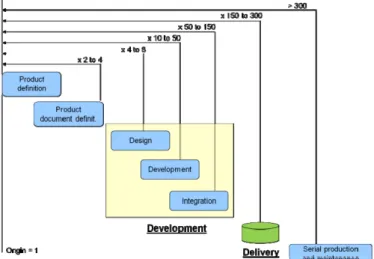
Other studies (Figure 1) provide an idea of the relative cost impact in relation with the defect detection in this V-Model [8].
Figure 1 : Cost for correction related to the detection process
To support designers to improve the model design and robustness, Johnson Controls is associated to partners, in the EDONA project, for the development of a generic tool for automatic test cases generation at the model level. This tool shall be able to interact with a standard environment for automatic validation and link to home-made tools. We will be able to generate test cases to verify back to back tests between model and code, up to system validation (when possible).
Once the model is developed and simulated, the designer performs the tests of the model. The tool takes on some structural test coverage such as dead lock detection, data overflow, unused algorithm part,
Model Coverage/Decision Coverage or signal ranges.
In addition to functional validation, this tool associated to other market tool for model management shall enable us to improve analysis for model coverage (MIL) and code coverage (SIL). We will be able to detect dead code or deactivated code, analyse functions and calls coverage and to reduce time before obtaining the first results.
This fills some requirements of ISO26262 standard [4] (see examples provided previously) to be able to reach up to the safety ASIL D level.
3. Safety Test Builder
Safety Test Builder (STB) is a Geensoft’s tool dedicated to automating the production of test cases for embedded software projects that have been modelled with Simulink® and/or Stateflow® from The MathWorks®. The tool, which is fully integrated with the Matlab environment, works with any standard Matlab blockset and provides easy extension using an “external tool” feature.
Test cases generated by STB are defined according to coverage objectives derived from user-defined criteria. Typical coverage criteria are:
• Functional coverage, where only the functions of the model are covered (i.e. the inputs/outputs, global MC/DC, etc). This is a kind of black-box strategy.
• Structural coverage, in which the test objectives are selected to exercise some or all of the model internal blocks. This is a typical white box strategy.
Once test cases are found, STB is able to export and optimize them either in number or size, to call the Simulink’s coverage tool to produce a coverage report, generate a Simulink test harness that can
check the model (or any implementation of it) against the expected inputs/outputs and to replay a specific test case step-by-step in order to find out why a model diverges from the expected behavior, etc. This list is actually open: by using the external tool feature, one can freely add new functions to STB. For instance in EDONA/WP3 we have developed a tool that exports the test case database into spread-sheets used by Johnson Controls’ tool chain (see section 5).
In order to find test cases, the model is automatically instrumented with extra Simulink blocks that detect when an objective is covered. Then STB uses Simulink’s native simulation modes (normal, accelerated or rtw-generated c-code) to execute heuristically-driven random walks in the model’s state space. This approach allows STB to cope with any standard block present in the model without worrying about the numerous parameters that can alter its semantics. Indeed, the scenarios found by STB accurately represent by construction the exact behavior of the model.
The speed of the heuristically-driven random search is rather good (half hundred thousand steps per second on a typical application like the ones of section 5). Therefore, in a few-seconds search, many millions steps are examined. This brute-force approach allows covering most test objectives very quickly (>80% coverage ratio is usually observed on industrial models). Obviously, hard-to find corner cases require longer search time.
Plotting a typical coverage ratio against the time-spent (see Figure 2) shows that it asymptotically converges to a limit. This means that if covering the first 80% of the test objectives is fairly easy, the
remaining 20% will require much more effort (not counting for unreachable objectives).
Figure 2: Coverage ratio in function of the time spent for random search
This stated, it appeared that in order to improve STB performance, a different technique should be used. Hence, in EDONA/WP3, an external tool has been developed, that uses the AGATHA engine by the CEA LIST (see section 4) in order to perform symbolic execution of the model, to reach corner cases and possibly prove which test objective is reachable or not.
As the AGATHA tool is not able to natively understand Simulink models, we had to find a way to translate Simulink’s semantics into the proper representation.
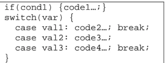
The formal semantic of Simulink models is hard to define because it is an industrial standard that contains many variants. It also slightly evolves with Matlab’s versions and is not publically available. However, when using the embedded coder of Real-Time Workshop, one gets C code that is semantically correct with respect to the model. Since the semantic of embedded C is rather clean, we have designed a technology that is able to transform (a subset of) C into AGATHA-compliant automata. This works in several steps. First the C code is read and an abstract syntax tree is constructed. That tree is then formally transformed in an internal form that represents an automaton, the states of which are the condition points present in the C code and the guarded out-transitions contain the decision
executed according to the condition. For instance, the following C code:
if(cond1) {code1…;} switch(var) {
case val1: code2…; break; case val2: code3…;
case val3: code4…; break; }
is translated into the following states and guarded transitions: s1 s2 s3 [cond1] code1… [!cond1] [var==val1] code2… [var==val2] code3…; code4…
[var==val3] code4… [var!=val1 && var!=val2 && var!=val3]
The C variables read and written in transitions coming out of different states are transformed into global state variables. Others are represented as transition specific local variables. Nested conditions (e.g. If() statements) simply add extra states in a way that prevents the explosion of the number of states. Globally the size of the produced automaton grows almost linearly with the size of the C code. Actually the defined technology is flexible enough to work on C code generated by other C-code generators such as Geneauto2 [6].
Overall the formal tool-chain added to STB works as follows:
1. Instrument the model using extra Simulink blocks, as usually done by STB.
2. Call a C generator (ERT coder or Geneauto2).
3. Read the C code with the proper reader (one for ERT, one for Geneauto2) and build an internal representation of the C code that is not generator dependent.
4. Translate that internal representation and all objectives into AGATHA’s format.
5. Launch the AGATHA tool.
6. Read the scenarios that have been found by AGATHA and inject them into STB’s database.
Using this tool-chain, we are now able to symbolically execute the Simulink model looking for corner cases not found with STB native algorithm and export them into Johnson Controls’ format, in order to perform hardware-in-the-loop simulations.
4. Test generation with AGATHA
The goal of the AGATHA tool-set is to help engineers to check if a model based on concurrent automata fits the user informal requirements. The idea is to symbolically execute ([1], [5]) the model in order to obtain a synoptic view of its behaviours. 4.1. Symbolic Execution
AGATHA derives a tree-like structure denoting all behaviours of the model. The tree nodes are snapshots which represent the symbolic states of the system during the execution at a given step. Here, a snapshot is a data structure named Execution
Context (Figure 3) which includes: • a Control State,
• a Path Condition, conjunction of the encountered guard to reach this context, • all symbolic variables values,
CS : s PC : x1 > y0 x = 2 * x1 y = y0 + x1
EC =
Figure 3: Execution Context
Let t be a transition like in Figure 4 which the source state s is include in the control state of EC.
Symbolic evaluation of t provides two new execution
contexts described by the which
corresponds of the two behaviours been inferred from a classical if-then-else statement.
Figure 5 s t s’ If x > 0 Then x = 2 * y + x Else y = x - y Figure 4: Transition
4.2. AGATHA workflow
In order to check the model according to the user objectives or connected tools like STB, AGATHA offers a set of execution (or behaviour) filters which can be configured to do structural or functional coverage among others. For example, the formula checker (verifier) filter needs a set of algebraic formula provided by the user.
The Figure 6 shows the AGATHA workflow perform behaviours selection according to user configuration (for filters) during an evaluation step. Three main agents sequentially work:
1. A Queue is used to store the waiting execution contexts. A Selector deals with the model search strategy like depth first, breadth first or random.
2. A Symbolic Execution engine.
3. A Controller manages filters.
EC EC Symbolic Execution EC EC1 EC2 Controller EC EC EC EC EC EC EC EC1 EC2 Execution Tree Queue EC1 EC2 Formula Checker Other Checker Selector
Figure 6: AGATHA workfow
4.3. Test generation
From the symbolic execution tree generated by AGATHA, we consider each behaviour path as a symbolic test case which represents an equivalence class of numerical tests. A constraint solver is used
to numerize each symbolic path which is a sequence of execution contexts. A test case contains one sequence of system cycles. Each cycle is made of values for all input / output system parameters. CS : s’
PC : x1 > 0 ⋀ x1 > y0 x = 2 * y0 + 4 * x1 y = y0 + x1
EC1 =
5. Use cases description
CS : s’
PC : x1 ≤ 0 ⋀ x1 > y0
EC2 = 5.1. Overview of models perimeter used
x = 2 * x1 y = 3 * x1 - y0
Figure 5: Symbolic Execution
To check the validity of concept, the perimeter taken into account is the product for battery management systems and body controller modules. More precisely some algorithms developed for the Johnson Controls Autosar prototype, the Tire Pressure Monitoring System (TPMS) and battery algorithm.
These models cover the typical use-cases algorithms we find in our company using Stateflow or Simulink blocks. Added to them we take into account some other models from Delphi and Renault.
5.2. Use case #1
In the first use case, we need to test an Autosar model developed with Simulink and dedicated to management of room, flashing and front/rear lamps. It is built with around 400 blocks, representing 19 kinds of block types.
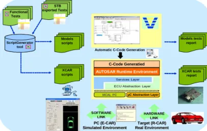
This model is used in the prototype developed by Johnson Controls to evaluate the migration from legacy architecture to Autosar architecture. This prototype is built with Simulink model for Autosar, C-Code generation and plugged on an Autosar ICC3 Basic Software. The whole software is tested into a standard validation environment at model level, and used for verification of tools migration for PC simulation and validation (XCAR), see Figure 7.
ScriptGenerator tool ScriptGenerator tool Models scripts Models tests report XCAR
scripts XCAR testsreport
STB exported Tests
Automatic C-Code Generation
µC Abstraction Layer MCAL PC
C-Code Generatied
AUTOSAR Runtime Environment
HARDWARE LINK SOFTWARE
LINK
Target (R Target (R--CAR)CAR) Real Environment Real Environment PC (E PC (E--CAR)CAR) Simulated Environment Simulated Environment Functional Tests
Figure 7: Johnson Controls Autosar PC and target validation overview
In association with the validation environment, STB/AGATHA tool, described in Figure 8, provides some tests and is connected to the Johnson Controls environment through the file exchange format. ScriptGenerator Matlab/Simulink scripts 3‐ XLIA generation 4‐ Test cases generation 5‐ Test cases execution 6‐ Test cases export 2‐ C‐Code generation
Safety Tests Builder Simulink Model AGATHA Excel Test cases description 1‐ Coverage criteria definition
Figure 8: Test environment at model level
This test environment is divided into 2 parts:
• STB/AGATHA tool: helps user to define tests coverage criteria, interact with the model (display test impact, test case execution) and generates test cases for Johnson Controls use. AGATHA produces test cases.
• Johnson Controls modeling test
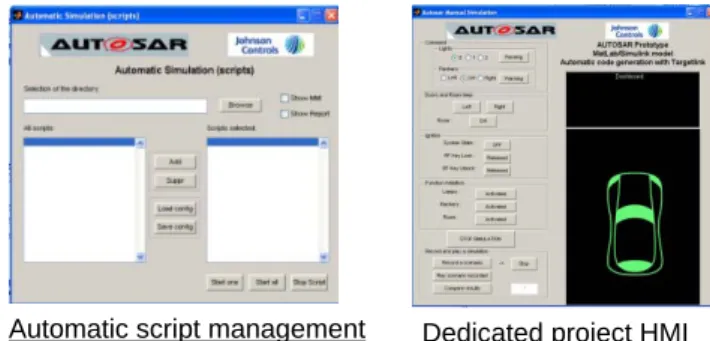
environment: a tool converts test cases to Matlab scripts then automatic execution in standard HMI interface which display execution and impact in a dedicated project window (figure 9).
Global validation model environment view
Standard HMI
Automatic script management Dedicated project HMI Figure 9: Johnson Controls standard HMI and
model validation environment
5.3. Use case #2
In the second use case, we test an algorithm developed with Simulink blocks for the Tire Pressure Monitoring System function. In this model we manage miscellaneous algorithms for tire pressure state monitoring (low or high pressure thresholds management, leakage detection, tire pressure associated to vehicle speed, sensor status verification) to provide alarm to the vehicle driver. The last release of this algorithm was used as specification then hand coded and integrated in serial ECU production since 2008 (300 000 parts per year).
This model is built with around 3300 blocks, representing 24 kinds of block types.
The environment is the same as described for the use case #1.
The goal of this use case is to check with the tool, a model developed in the past for serial production without association to automatic C-Code generation and to increase the perimeter of the model size taken into account.
6. Tool evaluation and feedback
From the industrial point of view, the STB/AGATHA tool in development, is user friendly and can be used intuitively.
The HMI enables to define easily the coverage criteria (even with possibility to create specific user menus for predefined coverage criteria), to generate the test cases, to view the impact on the model and to export to pre-defined format (.xls, .pdf, etc). The user can integrate new functionalities in the tool (inside the menu) using Matlab scripts (for example automatic rework of model for data typing, model check or rework for specific constraints, etc).
The current results of the evaluation phase, are promising regarding the potential of the tool to help in development for time saving, cost reduction and quality improvement.
The results seen on some example models need to be confirmed by using this tool on more models. Nevertheless, the tool needs to continue to be improved.
7. Conclusion and perspectives
The work which is described in this paper has the objective to provide an automated test generator, with a user friendly interface, and whose performances allow to be used in an industrial context. This objective must be reached in the year 2010, and the actual results confirm this planning. A possible extension of the tool is the verification of properties, because the use of the symbolic execution is a good way to verify temporal properties [10].
Another extension can be the use of the symbolic tree produced by symbolic execution to analyse the models ([2], [9]), and before generating test to choose the best test purposes [3].
With these extensions, the proposed toolset could offer more possibilities to different users and would allow them to give their feedback to the proposed verification and validation process.
8. References
[1] L.A. Clarke, “A System to Generate Test Data and Symbolically Execute Programs”, IEEE Transaction on Software Engineering, vol.SE-4 n.3, PP.178-187, September 1976.
[2] J-P. Gallois, C. Gaston, A. Lapitre, “AGATHA, un outil de simulation symbolic”, AFADL 2004, June 2004, Besançon (France).
[3] C. Gaston, P. Le Gall, N. Rapin, A. Touil, “Symbolic Execution Techniques for Test Purpose Definition”, TestCom06, May 16-18, 2006, New York.
[4] Draft International Standard ISO/DIS 26262, International Organization of Standardization, 2009.
[5] J.C. King, “Symbolic Execution and Program Testing”, Communication of the ACM, vol.19, n.7, pp.385, July 1976.
[6] http://gforge.enseeiht.fr/projects/geneauto
[7] J. Printz, CNAM UVGLG206/GLG207, 2006
[8] J. Printz, “Productivité des programmeurs”, Chapter 1.2.6, Page 41 of the quote, Hermes, 2004.
[9] N. Rapin, C. Gaston, A. Lapitre, J-P. Gallois, “Behavioral Unfolding of Formal Specifications Based on Communicating Extended automata”, ATVA, December 10-13, 2003, Taiwan.
[10] N. Rapin, “Symbolic Execution Based Model Checking of Open Systems with Unbounded Variables”, TAP 2009: 137-152.
9. Glossary
AGATHA: Atelier de Génération Automatique de Test
Holistique d’Automate
Autosar : AUtomotive Open System ARchitecture ASIL : Automotive Safety Integrity Level ECU : Electronic Control Unit
MIL : Model In the Loop
SIL : Software In the Loop
ISO : International Standard Organization MC : Model Coverage
DC : Decision Coverage
EDONA : Environnement de Développement Ouvert aux Normes de l’Automobile.
HMI : Human Machine Interface TPMS : Tire Pressure Monitoring System PC : Personal Computer
STB : Safety Tests Builder