HAL Id: hal-02156190
https://hal.archives-ouvertes.fr/hal-02156190
Submitted on 14 Jun 2019
HAL is a multi-disciplinary open access
archive for the deposit and dissemination of
sci-entific research documents, whether they are
pub-lished or not. The documents may come from
teaching and research institutions in France or
abroad, or from public or private research centers.
L’archive ouverte pluridisciplinaire HAL, est
destinée au dépôt et à la diffusion de documents
scientifiques de niveau recherche, publiés ou non,
émanant des établissements d’enseignement et de
recherche français ou étrangers, des laboratoires
publics ou privés.
PhiSystem: a tooled methodology for design and
validation of ADAS
Matteo Morelli¹, Philippe Fiani
2, Arnaud Cuccuru¹, Sebastien Gerard¹
To cite this version:
Matteo Morelli¹, Philippe Fiani
2, Arnaud Cuccuru¹, Sebastien Gerard¹. PhiSystem: a tooled
method-ology for design and validation of ADAS. ERTS 2018, Jan 2018, Toulouse, France. �hal-02156190�
Category: regular paper
Title: PhiSystem: a tooled methodology for design and validation of ADAS
Name and affiliation of author(s): Matteo Morelli¹, Philippe Fiani², Arnaud Cuccuru¹, Sebastien Gerard¹ ¹ CEA LIST, Laboratory of Model driven engineering for embedded systems, Point Courier 94, Gif-sur-Yvette, F-91191 France
² Sherpa Engineering, La Garenne Colombes, France
Keywords (in addition to the selection of the relevant conference topics to do on-line at submission): Model Based System Engineering (MBSE), ADAS, Simulation, requirement engineering
Introduction
Advanced driver-assistance systems (ADAS) are a class of cyber-physical systems (CPS) that increase car safety and driving comfort. ADAS represent a collection of key technologies for future self-driving vehicles. As a class of CPS, ADAS design is a complex task that naturally involves teams of engineers with different specialties such as requirements modeling, control design, software/hardware development, etc.
With the increasing adoption of ADAS towards truly autonomous vehicles, this task is made even more complex by the importance of taking into account domain-specific requirements and concerns, such as rules and laws, which can be seen as functional and legal requirements for the technology to be put in operation. This includes demonstrating conformance to standards (e.g., safety), considering cultural differences across regions in terms of, e.g., infrastructures and driver behavior, etc. On this last point in particular, Lindgren et al. [1] state that not taking these differences into account when designing ADAS increases the risk of ending up with a product that is not only unusable but also potentially dangerous.
As the complexity of ADAS design increases, a holistic methodology is required that is underpinned by formal modeling for all domain-specific concerns and encompasses the whole design process at system level. Systemic modeling naturally accounts for multiple viewpoints, as represented in Figure 1. The system engineering approach based on formal models allows accurate evaluation of multiple candidate designs according to many facets, such as system performance, safety, reliability, autonomy, energy consumption, etc. This, in turn, brings crucial competitive advantage for adopters, since it enables early-stage evaluation of design choices, keeps the development costs low and the time-to-market short.
In the context of the joint laboratory Sherpa@LIST, the company Sherpa Engineering1 is developing in partnership with the CEA’s lab LISE a systemic modeling tool, named PhiSystem, which aims at supporting such a holistic methodology. PhiSystem leverages modeling and simulation to implement a top-down approach for the design of CPS. PhiSystem is based on the SysML standard and the Papyrus2 technology. It accounts for multiple viewpoints to enable the definition of requirement, system mission, test, as well as architecture
(functional and physical) models. This allows the designer to link the real system with the system objectives and its functions. Fast transition between system definition and simulation models —e.g., Simulink— enables the verification of system performances against requirements, along the overall design phase, and improves consistency and traceability of simulation models with respect to system definitions. It also provides support for system definition itself by anticipating simulation in early phases.
In this paper, we present the application of PhiSystem to ADAS design and verification, with a focus on its modeling and simulation capabilities and the link with Simulink. In the sections that follow, we describe the top-down methodological workflow behind PhiSystem, as well as companion tools and frameworks that support it. Next, we outline an application to design and simulation-based verification of a set of functions for self-driving cars. We then position our work with respect to the state of the art. Finally, we summarize our major results.
Methodology for ADAS design and verification
Our methodology complies with the “System Design” sub-clause of EIA 632 [2] standard for system
engineering. It fosters a collaborative workflow between system and simulation engineers, who work together but use different modeling and development tools. The methodological workflow as applied to ADAS design and verification is represented in Figure 2.
1http://www.sherpa-eng.com 2http://www.eclipse.org/papyrus/
Figure 1 Holistic methodology enables thorough assessment of multiple ADAS design criteria
Figure 2 Methodological workflow for ADAS design and verification by simulation The first step concerns the modeling of requirements and vehicle end-missions. At this stage, the customer specifies the requirements for what concerns safety, performance and quality aspects. The system engineers use SysML and PhiSystem to define the stakeholders and the associated requirements for each stakeholder.
Examples of such requirements are conformance to civil code and traffic laws, and to ISO26262 standard for road vehicles functional safety. The main vehicle’s capabilities are identified as well, such as mobility,
navigability and livability. Models of vehicle’s end-missions are conceived and the stakeholder requirements are allocated to the end-missions.
In the second step, system engineers model the vehicle’s key functions in the so-called Logical Solution Definition. The system’s functional architecture is represented at a high level of abstraction as a set of
interconnected functional units. Examples of such functional units are motion and navigation, which are made of sub-units such as perception, localization and vehicle guidance. Other examples include energy management and thermal comfort. Test scenarios are defined as well, according to required use cases. Automated tools process the high-level functional and test scenario (SysML) models and generate a Simulink model which is used by
simulation engineers to prototype and validate control strategies and algorithm ideas at the early phases of design process. Unsatisfactory performances from simulation verdicts may trigger design iterations, where, e.g., end-mission requirements or their allocation to vehicle’s key functions are refined. At this stage, models can even evolve concurrently: model refinements, such as changes to interfaces of functional units, connections re-routings, etc., can occur on both sides—at system level and/or simulation level. To address model synchronization issues, PhiSystem features round-trip engineering capabilities to automatically maintain consistency between models, by incrementally updating one model to reflect changes made to the other model.
Once the functional architecture and the (prototype) control logics have been validated at a high-level of abstraction, the system engineers refine the model to achieve the so-called Technological Solution Definition. It represents the system’s physical architecture as interconnected physical units, including, e.g., cameras, lidar, electronic and software architectures, batteries. The (SysML) models of physical units explicate the low-level realization choices for the vehicle’s key functions. At this stage, functional requirements are allocated to physical units and test scenarios models are defined as well. As in the previous stage, a Simulink model enables
simulation engineers to validate the performance of controlled system against requirements and design iterations are performed if requirements are not met.
Tools supporting the methodological workflow
Apart from PhiSystem, other tools and frameworks support our top-down methodology. PhiSim is a Simulink-based package developed by Sherpa Engineering, which allows building complex CPS using sets of reusable library elements, including ADAS models for drivers, cars and their environment. PhiSystem provides a SysML model library of components to represent the functional and physical units at system level. It uses the UML profile mechanism to extend SysML to model concepts in the CPS domain. Through specific stereotype attributes, every component is linked to the corresponding PhiSim executable model, which is a Simulink block in the PhiSim blockset at simulation level. Additionally, every component instance in the models can be configured through a set of exposed properties.
The Massif framework3 is used as the bridge connecting PhiSystem and PhiSim. Massif supports the
representation of Simulink models and libraries (such as PhiSim) in the Eclipse Modeling Framework (EMF). It also features a dedicated API that enables Java RMI-based communication with a running Matlab instance.
Automated tools transform PhiSystem models into Simulink/PhiSim models in two sequential steps. First, a model-to-model (M2M) transformation processes the PhiSystem model and produces an intermediate (Massif)
model representing the Simulink/PhiSim equivalent model in EMF format. Second, the intermediate model is processed by a model-to-text (M2T) transformation that produces a set of Matlab scripts with construction commands. Once executed, these scripts create the .slx model which simulation engineers work with. Scripts’ execution is automatically performed via the Java RMI framework at the end of the generation process, which is perceived by designers as a single-step. It is referred to as batch generation because the code in the Matlab scripts (and hence the .slx model) is generated from scratch, i.e., any existing code is overwritten by the newly generated code. Note that, simulation engineers implement the control logics as blocks in Simulink libraries, which are automatically linked to the generated model. This mechanism prevents control logics to be overwritten by subsequent batch generations.
Consistency between SysML (/PhiSystem) and Simulink (/PhiSim) models which evolve concurrently is achieved through the process depicted in Figure 3. After batch generation at time t=t°, Simulink and SysML models are modified concurrently. Modifications to the two models produce models slx¹ and sysml², respectively
3https://github.com/FTSRG/massif
Matlab EMF
at times t=t¹ and t=t². To synchronize them, models are transformed to the intermediate Massif format (green rectangles with blue borders), which represents the common semantic domain where Simulink and SysML models can be compared. Models massif, massif¹ and massif² act as synchronization artifacts in a 3-way
comparison, which operates on top of the EMF-Compare4 framework. In this phase, the detected differences are displayed to the user, who may need to resolve conflicts manually. Finally, the differences are propagated (merged) to the models slx¹ and sysml² to produce slx³ and sysml³.
Application to design and verification of autonomous driving functions
We now outline an application of our tooled methodology to design and simulation-based verification of a set of functions for self-driving cars. We consider autonomous cars driving onto tracks according to given paths and specific profiles. Driving profiles can conform to the traffic laws or be representative of, e.g., firefighter vehicles driving in mission mode (i.e., as fast as possible). Tracks include zones with (different) speed limitations, zones where overtaking is permitted (or not), pedestrian crossing signs and traffic lights.
The initial step consists in modeling a vehicle’s end-missions as a set of capabilities that realize each mission. As an example, mobility is one of the fundamental capabilities that realize the autonomous driving mission and represents the ability of the vehicle system to move on the track. At this stage, the key functions which implement it are not yet defined. First, a set of stakeholders must be identified and requirements must be associated to each stakeholder (Figure 4(a)). Mission requirements are expressed at high level, whereas derived requirements correspond to requirements at the level of the system capabilities.
Derived requirements may indicate, e.g., that the vehicle control system shall ensure a maximum consumption for a NEDC5 equal to 3.3 l/100km. Or that the vehicle dynamics (sizing) shall ensure a maximum speed of 180km/h and a maximum acceleration —from 0 to 100 km/h— of 11s. Or, again, that turn into a road bend (with no traffic) shall perform (i) smooth release of acceleration pedal, (ii) smooth increase of steering angle during the turning maneuver and (iii) smooth decrease of the same quantity to come back to straight motion —where smooth actions on pedal and steering wheel are formally defined by appropriate mathematical functions. Derived requirements provide quantitative descriptions of the desired system performance: generally, they are not expressed just as simple text, but are encoded in a computer-processable form and reflect constraints which are later evaluated against simulation results to verify requirements’ satisfaction.
The next level is that of Logical Solution Definition. The transition between the two levels consists in a copy of the structure hierarchy of elements in the source domain to the target domain. UML Realization artifacts with a «Map» stereotype applied are created between elements in the two domains, to enable the propagation of requirements from the Stakeholder and Mission Definition to the Logical Solution Definition level (Figure 4(b)).
4https://www.eclipse.org/emf/compare/
5https://en.wikipedia.org/wiki/New_European_Driving_Cycle
Figure 4 (a) Portion of requirements for mobility. (b) Tool-assisted domain change from Mission Definition to
The whole process is tool-assisted to provide the designers with a robust yet simple-to-use mechanism for cross-domain propagation of requirements.
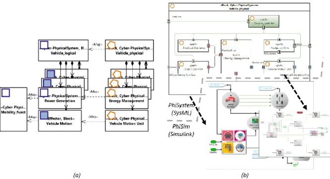
The Logical Solution Definition describes the system as a set of interacting functional units that realize the vehicle’s capabilities. As an example, the PowerGeneration unit, contributes to the realization of a vehicle’s mobility. It is made of reusable components from domain-specific PhiSystem libraries, as shown in Figure 5(a). We validate a prototype implementation of energy management system at this level, the functional architecture level.
Each component is mapped to the corresponding PhiSim implementation through specific stereotype attributes. Figure 5(b) shows how the mapping mechanism between PhiSystem and PhiSim reusable blocks works for a library element that models a car’s braking system. The libQualifier and libBlockName attributes of
Figure 5 (a) Definition of functional architecture and of energy management sub-unit. (b) Mapping between the
Supplier stereotype applied to BrakingSystem (red box) are combined to provide a unique reference to the corresponding PhiSim model that provides the executable (Simulink) behavior.
A similar approach enables the mapping between *_Control blocks and their Simulink implementation. The control logics is encoded in dedicated blocks distributed by simulation engineers as Simulink model libraries, which are referenced by the libQualifier and libBlockName attributes of Supervisor stereotype applied to
*_Control blocks. Batch generation automatically links those blocks to the generated Simulink model, without overwrite them.
Figure 5(b) also shows the set of properties exposed by BrakingSystem (blue box), namely the maximum braking torque by wheel (Cmax), wheel radius (R) and number of wheels (N). Every component instance in PhiSystem can be configured. The automated tools process those values and initialize the mask of the generated PhiSim component accordingly.
The described mechanism realizes a smooth integration in the Simulink environment of models of functional architecture and supervision logics. Design iterations are triggered in case simulation verdicts result in unsatisfactory performances. Refinements may include concurrent adjustments to architectural design and control strategy models. Consistency between models is maintained by the round-trip engineering capabilities featured by PhiSystem.
When requirements are met at the level of Logical Solution Definition, we move down to the next level of abstraction, that of Technological Solution Definition. Again, domain change is tool-assisted and allows for the propagation of requirements from functional to physical architecture domain (Figure 6(a)). Integration in the Simulink environment of (physical) architecture and control models (Figure 6(b)) enables us to validate the performance against requirements. As in the previous stage, design iterations are performed if performances are unsatisfactory.
The Technological Solution Definition is the lowest level of abstraction, where the low-level realization choices for the vehicle’s key functions are explicated. We validate perception, localization and guidance at this level. These functions, that realize mobility and navigation capabilities, must comply with traffic and driving regulations. We assume that a number of traffic law requirements have been modeled, e.g., as a refinement of model of Figure 4(a).
Figure 7 and Figure 8 show simulation verdicts of 4 scenarios considering different conditions of traffic flow (no traffic, number of cars, etc.), driving profiles, number and position of traffic lights, unexpected situations (e.g., Figure 6 (a) Tool-assisted domain change from Logical to Technological Solution Definition, to enable cross-domain propagation of requirements (focus on a subset of key-functions that realize mobility). (b) Simulink model of physical architecture.
stopped car in the middle of the road). Verdicts are in form of 3D visualization and time series of monitored variables that are representative of requirements to be met in those conditions (e.g., the smooth actions on pedal and steering wheel mentioned above).
The first scenario is that of a car driving in a free road, i.e., with no traffic or with other cars far from its current position. Figure 7(a) shows an autonomous vehicle that meets the requirements in this scenario. It performs correct longitudinal motion while moving within its own lane. It also does not cross the dashed line in the middle of the road and perform smooth actions while decreasing the velocity and actuating the steering wheel to execute the turn. Nevertheless, Figure 7(b) shows a vehicle in the same scenario that exhibits an unexpected behavior — line change— in proximity of a road bend. This may indicate a flaw in the realization of functions featuring mobility and navigation capabilities. Therefore, additional design iterations are required to meet the requirements.
Figure 7(c) and Figure 7(d) represent mission executions in the second and third scenario, respectively. In these scenarios, a self-driving car identifies a stopped vehicle (obstacle) and must take appropriate decisions and Figure 7 3D visualization of self-driving cars’ behaviors for 4 test scenarios. For every row (a)—(e), the
sequence of frames reads from left to right. (a) A vehicle drives correctly in a free-road scenario. (b) Still in a free-road scenario, unexpected lane change in proximity of a road bend. (c) A vehicle takes appropriate actions when a stopped vehicle at a red-state traffic light is detected. (d) A vehicle identifies a stopped vehicle in the middle of the road and takes appropriate actions. (e) Correct vehicle overtaking in a bend of a two-lane road.
actions. In Figure 7(c), the car’s perception unit detects the presence of a red-state traffic light. According to traffic regulations, the guidance unit stops the car without attempting an overtaking maneuver, even though the 2-lane road could permit it. In Figure 7(d), the perceived stopped vehicle stands still in the middle of the road and the car correctly avoids it—the car performs lane-change, goes straight, leaves reasonable space to pass and moves back into the original lane.
Finally, the fourth scenario concerns the verification of correct overtaking maneuver in a bend of a two-lane road. Figure 7(e) shows that the faster self-driving car approaches the slower vehicle in a bend and overtakes it in conformance with driving rules.
Positioning with regard to the state of the art
The automotive industry is investing significant resources to develop and commercialize ADAS technology, but the definition of an engineering process that supports collaborative multi-domain modeling and enables early stage verification of requirements and system performance is still a challenge.
Electronic Design Automation (EDA) companies focus on hardware aspects, such as design and verification of systems on chips and processor IP. As an example, Cadence [3] adopts a holistic design approach to optimize performance and meet safety standards in ADAS applications. This kind of approach addresses implementation concerns to support the realization of final system and can complement the PhiSystem approach.
Other tools address ADAS design needs only partially and do not provide support for a holistic approach similar the one implemented by PhiSystem. Rhapsody [4], Enterprise Architect [5] and Reqtify [6] focus on MBSE. These tools provide functionalities similar to PhiSystem regarding high-level system modelling and requirement engineering, but have limited simulation capabilities. The dSPACE platform for ADAS [7] features rapid control prototyping, and hardware-in-the-loop (HIL) simulation. However, it does not support collaborative modeling with MBSE tools. Similar considerations hold for other tools that focus on simulation, such as CarSim [8] and Amesim [9].
ADAS are a class of CPS that is cross-cutting in nature, i.e., they combine many concerns and relate to several levels of abstractions. This makes their design a complex task, where the adoption of concern-specific tools alone —e.g., Rhapsody (or equivalent), Simulink (or equivalent) and Reqtify (or equivalent)— is not sufficient, and automated and systematic integration of heterogeneous models plays a key-role. In a sound, collaborative, model-based flow, automated and systematic model integration improves the efficiency and also guarantees that no errors are introduced in a manual (integration) stage. This motivates the work we do on PhiSystem to provide fast (bi-directional) transition between system definition and simulation models. Of course, this brings additional complexity to the deployment of the methodology, which involves all the stakeholders in the design process. To overcome this issue, a support process must be created, with training —a good estimate being 3 days— and, in some companies, with continuous modeling assistance provided by a specialized team.
A number of tools started adopting the FMI standard to support a collaborative MBSE flow. However, this support [10] is still often incomplete and/or compatible with old versions of the standard, or it comes via Figure 8 Time series of monitored variables from experiments of Figure 7. (a) Smooth speed decrease and
action on the steering angle of vehicle of Figure 7(a). (b) Lane shift of vehicle of Figure 7(b). (c) Actions on acceleration and brake pedals of vehicle of Figure 7(c), and consequent smooth decrease of vehicle speed.
expensive add-ons. We develop tool-support for FMI in PhiSystem in the context of the ITEA3 research project OpenCPS [11].
Conclusions and future work
In this paper, we present PhiSystem and the EIA 632-compliant methodological approach behind it as applied to the development of ADAS —a class of CPS that are complex to design because of their cross-cutting nature. PhiSystem leverages modeling and simulation to support a holistic, model-based system engineering process. PhiSystem integrates with Simulink to enable collaborative workflow between system and simulation engineers. Systemic modeling and simulation allow early assessment of aspects such as performance, safety, reliability, etc., and represent key capabilities when dealing with the design of ADAS. Early-stage evaluation of candidate designs is crucial in such a class of systems/applications, because it reduces design iterations and eliminates costly and time-consuming re-design cycles.
PhiSystem includes models and libraries of components that are suitable for ADAS applications. We outline an application of PhiSystem to design and simulation-based verification of a set of functions for self-driving cars. The focus is on its modeling capabilities—vehicles' end-missions, stakeholders and associated requirements; interconnected functional units representing the functional architecture; interconnected physical units defining the physical architecture; tool-assisted transition between levels enabling cross-domain propagation of
requirements— and the link with Simulink. We outline how the performance of supervisory logics of perception, localization and guidance key-functions is evaluated against traffic law requirements in a number of different scenarios.
Performance validation, though, is just one facet of multi-viewpoints approach that PhiSystem aims at
supporting (Figure 1). We are currently working on enabling full support of models and techniques that allow for thorough assessment of safety —ISO26262— concerns conjointly with those of (control) performances. This includes analysis such as HARA, FME(C)A/FME(D)A and FTA.
Another ongoing work is on the use of monitoring tools such as ARTiMon [12] to achieve fully-automate comparison of simulation traces against computer-processable specification of requirements. This work paves the way towards the implementation of a “decisional cockpit” that uses optimization procedures to assist the designers during the whole design process.
References
[1] Lindgren, A., Chen, F., Jordan, P. W., & Zhang, H. (2008). Requirements for the design of advanced driver assistance systems-The differences between Swedish and Chinese drivers. International Journal of Design, 2(2) [2] SAE International (2003). EIA 632: Processes for Engineering a System.
[3] Qi, C., & Robinson, N. Developing Smarter, Safer Cars with ADAS IP. Cadence Design Systems, Inc., 2017.
https://ip.cadence.com/uploads/1195/cdn-wpt-auto-ip-sys-design-enablement-pdf
[4] Rational Software. Rational Rhapsody.http://www.ibm.com/software/awdtools/rhapsody/ [5] Sparx Systems. Enterprise Architect.http://www.sparxsystems.com/products/ea/
[6] Dassault Systèmes. Reqtify. https://www.3ds.com/products-services/catia/products/reqtify/
[7] Patil, K. Speeding Up the Development of ADAS Systems with Model-Based Development. dSPACE Inc., 2016. https://www.dspace.com/en/inc/home/news/engineers-insights/blog_inc_adas_1607.cfm
[8] Mechanical Simulation Corporation. CarSim.http://carsim.com/products/carsim/index.php
[9] Siemens. Amesim. https://www.plm.automation.siemens.com/en/products/lms/imagine-lab/amesim/ [10] Functional Mockup Interface (FMI) Support in Tools. http://fmi-standard.org/tools/
[11] ITEA 3 - Project - 14018 OPENCPS. https://www.opencps.eu/
[12] Rapin N. Reactive Property Monitoring of Hybrid Systems with Aggregation. In: Falcone Y., Sánchez C. (eds) Runtime Verification. RV 2016. Lecture Notes in Computer Science, vol 10012. Springer, Cham