TECHNICAL REPORT
Feasibility study of simultaneous physical examination
and dynamic MR imaging of medial collateral ligament knee
injuries in a 1.5-T large-bore magnet
Ueli Studler&Lawrence M. White&Melanie Deslandes&
Christopher Geddes&Marshall S. Sussman&
John Theodoropoulos
Received: 2 October 2009 / Revised: 26 December 2009 / Accepted: 11 January 2010 / Published online: 14 February 2010 # ISS 2010
Abstract
Objective To determine the feasibility of evaluating medial knee joint laxity with dynamic magnetic resonance (MR) imaging and simultaneous physical joint examination in a large-bore 1.5-T system.
Materials and Methods The study included 10 patients (5 women, 5 men; mean age 35 years) with clinically diagnosed and categorized acute injuries of the medial collateral ligament (MCL). Intermittent valgus stress was applied separately to both the affected and the contralateral knee joint during dynamic MR imaging with a two-dimensional fast low-angle shot sequence. The width of the medial joint space and the opening angle between the femoral condyles and the tibial plateau were measured. Results obtained from dynamic MR imaging of the affected knee were compared with morphological MCL changes on
static MRI, to kinematics of the contralateral side and to the clinical grading of MCL injuries.
Results On clinical examination, all patients had grade 2 MCL injuries except one, who had a grade 1 lesion. Using morphological MRI criteria, 9 grade II and 1 grade III injuries were seen. Mean medial joint space width and opening angles of all affected knees were 2.8 mm and 2.7° respectively, compared with 1.7 mm and 2.1° on the contralateral side. The Wilcoxon signed rank test indicated that the differences in width (P=0.005) and opening angle (P=0.037) between the affected and contralateral knees were significant.
Conclusion Dynamic MR imaging and simultaneous physi-cal joint examination is feasible. Our results suggest that this technique might enable the imaging documentation of medial ligamentous knee instability.
Keywords MRI . Medical collateral ligament . Knee . Physical examination
Introduction
A complete characterization of joint pathology often requires an assessment of both the structure and function of the joint. Imaging is used to assess structural changes such as alterations in the morphology of joint surfaces, bones, ligaments, or myotendinous units. To characterize function, it is necessary to assess the joint in motion and under stress. This is accomplished through a physical examination in which the joint is manipulated by a clinician. While diagnoses are often made on the basis of the physical examination alone, acquiring simultaneous images of the joint in motion during a physical examination
U. Studler
:
L. M. White:
M. Deslandes:
M. S. SussmanDepartment of Medical Imaging, Mount Sinai Hospital and University Health Network, University of Toronto, 600 University Avenue,
Toronto, ON M5G 1X5, Canada
C. Geddes
:
J. TheodoropoulosDivision of Orthopedic Surgery, Mount Sinai Hospital and University Health Network, University of Toronto, 600 University Avenue,
Toronto, ON M5G 1X5, Canada Present Address:
U. Studler (*)
Department of Radiology, University Hospital Basel, Petersgraben 4,
4031 Basel, Switzerland e-mail: [email protected] DOI 10.1007/s00256-010-0884-6
may provide additional diagnostic information [1]. In practice, this is rarely done because of limitations inherent in current imaging techniques. X-ray fluoroscopy provides an excellent depiction of osseous structures. However, it is of limited value in the assessment of soft tissue structures including ligaments, tendons, and cartilage. X-ray expo-sure to both patient and physician is also an impediment to routine use. Similarly, ultrasound provides excellent delineation of some soft tissue structures. However, it cannot penetrate osseous anatomy, or image deep intra-articular structures critical to normal physiological joint function [2]. A possible alternative imaging modality that could be used to assess joint function is MRI. In the past, MRI has been used to assess motion patterns in a variety of joints, including the ankle, the knee, and the gleno-humeral joint [3–5]. Unlike other imaging modalities, MRI provides an excellent multiplanar depiction of bone and soft tissue in all aspects of the joint. It is already the gold standard in the assessment of many aspects of joint structure. However, for the purpose of assessing joint function, one key limitation of MRI is that, because of physical constraints of conventional MR scanners, it is generally not possible for a physician to physically manipulate the joint during an imaging examination. However, recently introduced high-field, short-length, large-bore magnets allow for much greater access to the patient during a scan.
The specific clinical application considered for this study is the assessment of medial collateral ligament (MCL) injuries in the knee. MCL injuries of the knee were chosen as a dynamic model of joint dysfunction for several reasons. The MCL is the principal stabilizer of the medial joint compartment [6, 7], making the MCL ideal for a correlative study between morphology and function. This primary role of the MCL in resisting valgus force also renders the ligament vulnerable to injury. As a result, the MCL is reported to be the most frequently torn ligament of the knee joint in different sports [8,9]. Another advantage of MCL injuries as a kinematic model is that the ligament is clearly depicted on MR images and that the knee joint space is relatively large so that quantitative assessment of joint space opening on stress imaging becomes possible. Currently, the classification of MCL rupture is based on clinical examination criteria reflecting joint instability under stress testing [10,11].
The objective of this study was to assess the feasibility of performing a simultaneous physical and dynamic MRI examination of a joint on a large-bore MRI scanner. We hypothesize that dynamic MR imaging performed simultaneous to the physical examination is capable of detecting differences in affected and contralateral tibiofe-moral joint opening in patients with unilateral MCL injuries.
Materials and methods
Patients and physical examination
The study was approved by the local institutional review board and all patients signed informed consent prior to enrollment. Patients were eligible for the study if they had a recent injury of the knee and the physical examination revealed an MCL injury. Exclusion criteria were gross signs of multiligament injured knees or prior knee surgery. During the study period (December 2008 to June 2009), 10 consecutive patients (5 women, 5 men; 3 left and 7 right knees) met the inclusion criteria. Mean age at the time of imaging was 35±12 years (range, 17–51 years). Mean patient height was 1.74±0.11 m (range, 1.64–1.92 m), mean weight 73±16.5 kg (range, 56–99 kg), and mean body mass index (BMI) was 23.8±3.2 kg/m2(range, 21– 28 kg/m2). All patients were seen in the orthopedic outpatient clinic by an orthopedic sports medicine specialist (J.T.) who evaluated the patients and established the clinical grading. The clinical classification system was based on a three-point scale: grade 1, tenderness limited to the ligament, full stability to valgus stress at 30° flexion; grade 2, increased medial opening to valgus stress at 30°, firm end point; grade 3, gross instability without a definite end point to valgus stress at 30° or 0° knee flexion [10].
Dynamic and routine MR imaging protocols
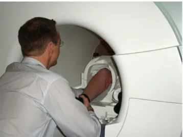
Imaging was carried out on a 1.5-T Siemens MAGNETOM Espree MRI scanner (Siemens Medical Solution, Erlangen, Germany). The magnet on this scanner has a large 70-cm diameter bore, and is 125 cm long. This configuration allows for ready clinician access to the patient (Fig.1). As a result, it is possible to perform MR imaging and a physical examination simultaneously.
The scan protocol consisted of the following. First, the affected knee was examined with our standard knee protocol (Table 1) using a dedicated eight-channel trans-mit–receive knee coil. Next, dynamic MR imaging and simultaneous physical examination were performed. This procedure was performed separately for affected and contralateral (control) knees. Patients were examined in the supine position with the knee placed in a four-channel transmit–receive neck coil. The neck coil was chosen for its open spatial design, which allowed the manipulation of joints within the coil (Fig.1). Images were acquired in the oblique coronal plane with a two-dimensional fast low-angle shot sequence (2D FLASH) and with an iPAT (integrated parallel acquisition technique) factor of two. The rest of the imaging parameters are summarized in Table1. The temporal resolution of this scan was 0.5 s. In order to obtain the most appropriate imaging plane, three
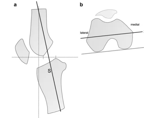
slices were planned at different positions with the exam-iner’s hand placed behind the knee, which was at approximately 30° of flexion. The oblique coronal views were oriented along the long axis of the tibia on sagittal localizer images (Fig. 2a) and along a line parallel to the posterior aspect of the femoral condyles (Fig.2b). The first slice was centered through the medial femoral epicondyle (Fig.2b). The other slices were parallel to the first one and were placed 7 mm anteriorly and posteriorly to the initial plane. Forty images per slice were acquired at a rate of two
frames per second while the examiner manipulated the knee joint with intermittent valgus stress.
Image analysis
An assessment of pathology was performed independently on both the static morphological MR images and the dynamic functional MR images. Evaluation of all images was performed with open-source software (OsiriX 3.3.2; the OsiriX Foundation, Geneva, Switzerland; available at
www.osirix-viewer.com, accessed 2 April 2009).
Standard morphological MCL changes were evaluated from images acquired with the routine (i.e., static) MR protocol. Tears were classified according to the description of Schweitzer et al. [12]: grade I, edema around an intact MCL; grade II, partial tear of the ligament with internal high signal; grade III, complete tear with complete discontinuity of the ligament. The anterior cruciate ligament (ACL), the posterior cruciate ligament (PCL), and the lateral collateral ligament (LCL) were assessed for structural integrity by using a three-point scale: a, intact ligament; b, partial tear (increased internal signal); c, complete rupture (discontinuity of the ligament).
Functional changes were assessed through an evaluation of joint space openings on the dynamic MR images according to the following protocol. First, the images with the greatest magnitude of medial joint laxity were chosen on the basis of visual inspection. The width of the medial joint space was defined as the difference between the medial tibial and femoral cortices at maximal and minimal opening. It was defined by drawing a perpendicular line at the medial tibial margin to a line drawn tangentially to the
Fig. 1 The short, large-bore Siemens MAGNETOM Espree MRI scanner allows the examiner access to the patient during an MR scan. The photograph was obtained while the examiner manipulated the knee joint with intermittent valgus stress. The examiner stabilizes the knee with one hand, while the other applies a valgus force at the ankle. The knee joint is positioned in the neck coil
Table 1 Sequence parameters for routine MR imaging and the dynamic study of the knee
Parameter Standard protocol Dynamic imaging
T2-weighted FSE fat saturation Intermediate-weighted FSE Intermediate-weighted FSE T2-weighted FSE fat saturation 2D FLASH
Plane Axial Coronal Sagittal Sagittal Oblique coronal
Repetition time (ms) 4,540 4,130 3,020 4,100 7.8
Echo time (ms) 69 40 20 72 3.3
Field of view (mm) 140×140 140×140 140×140 140×140 180×180
Matrix size (pixel) 256×256 512×256 320×256 256×230 128×128
Flip angle (°) 90 90 90 90 20
Thickness (mm) 4 4 4 4 10
NEX 2 1 2 2 1
Echo train length 12 10 10 8 N/A
Bandwidth (Hz/pixel) 250 100 260 250 200
Pixel size (mm) 0.5×0.5 0.3×0.5 0.4×0.5 0.5×0.5 1.4×1.4
T2w = T2-weighted; FSE = fast spin-echo; 2D FLASH = two-dimensional fast low-angle shot; n/a = not applicable; NEX = number of signals acquired
cortex of the medial and lateral femoral condyles (Fig.3). The length of the perpendicular was then measured. The difference in the angle between a tangent connecting the femoral condyles and a line along the tibial plateau was recorded at maximal and minimal opening respectively (Fig. 3). Measurements were first taken independently by two fellowship-trained musculoskeletal radiologists (M.D.,
with 2 years’ experience, and U.S., with 3 years’ experience in musculoskeletal radiology) who were blinded to the clinical results. At a consensus reading, both readers then reviewed all discordant measurements and evaluated mor-phological ligamentous alterations.
Data analysis
Differences in widths and angles between maximal and minimal joint opening were tested for interobserver agreement by using interclass correlation coefficients (ICC). Data obtained from consensus reading were pro-cessed for affected vs contralateral side comparisons, and for comparisons with the clinical and morphological results. Differences between measurements from the affected and contralateral sides were analyzed by using the Wilcoxon signed rank test. P<0.05 was considered to indicate a significant difference. Subgroups according to sex were also assessed. Analyses were performed with SPSS for Windows (Release 17.0.0; SPSS, Chicago, IL, USA) and R ® Development Core Team (2008), http://www.R-project.org, accessed 2 April 2009).
Results
Clinical findings
Among the 10 patients enrolled in this study, 9 had a grade 2 and 1 had a grade 1 MCL injury at physical examination
Fig. 2 Schematic drawings show how the oblique coronal views were acquired for the dynamic MR examination. The oblique coronal views (S) were oriented a along the long axis of the tibia on sagittal localizer images and b parallel to the posterior aspect of the femoral condyles (S) on axial localizer images. The first slice was centered through the medial femoral epicondyle (b)
Fig. 3 Schematic drawing illustrates the measurement techniques for obtaining the joint space width and the joint opening angle. For the joint space width, a perpendicular (P) at the medial tibial margin was dropped to a line drawn tangentially to the cortex of the medial and
lateral femoral condyles (Tf). The opening angle was defined as the
angle formed by a tangent connecting the femoral condyles (Tf) and a
line along the tibial plateau (Tt). Both measurements were recorded at
(Table 2). Injuries were sustained during skiing (n=4), playing ice hockey (n=4), soccer (n=1), and playing beach volleyball (n=1). The time period between the injury and the MRI ranged from 3 to 39 days (mean 24 days).
Morphological and dynamic MR imaging findings
In 8 patients the morphological MRI grading revealed a grade II injury (Table2). In 2 cases, there was disagreement as to the grade of injury between the clinical and static MRI morphological system. One of those 2 patients showed a grade 1 injury clinically, whereas MRI depicted a grade II injury; in the other patient, clinical examination showed a grade 2 injury, whereas the injury was categorized as a grade III injury on static MR images. Concomitant injuries on MR imaging included a complete ACL tear in 1, a partial ACL tear in 2, a partial PCL tear in 3, and a partial LCL tear in 2 patients. Interobserver agreement was excellent, with a range of ICCs from 0.89 (width in the affected knee) to 0.94 (opening angle on the contralateral side).
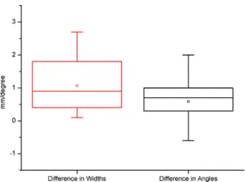
Table2 also indicates the results of the dynamic study. Columns 5–8 indicate that the overall width and angles are larger on the affected side as on the contralateral side. Column 9 indicates that the mean difference in width between the affected and contralateral knees is 1.1 mm (95% CI: 0.5–1.8 mm). The Wilcoxon signed rank test indicates that this difference is significant (P=0.005). In fact, all individuals in this study demonstrated a larger width in affected than in contralateral knees. Column 10 indicates that the mean difference between joint opening
and closing angles was 0.59° (95% CI: 0.05–1.1°; Fig.4). This difference was statistically significant (P=0.037). Note that, unlike the width measurements, 2 patients showed slightly greater opening angles in the contralateral knee compared with the affected side, although there was no history of MCL injury on the contralateral side.
Measurements from a patient with a clinical grade 1 injury (width for affected and contralateral side: 2.3 mm and 1.9 mm) did not differ from measurements in patients with grade II lesions. Likewise, measurements from a grade III MCL injury based on MRI criteria (width for affected and contralateral side: 3.5 mm and 1.4 mm) were similar to grade 2 lesions (Fig. 5). However, with only 2 patients having a grade other than 2, there are not sufficient data to adequately assess these results.
The greatest difference in medial joint space width between minimal and maximal opening was 4.9 mm (2.1 mm on the contralateral side) in a patient with a grade 2 injury (Fig.6). Differences between joint opening and closing were found to be smaller in women, for both the affected (mean width 2.6 mm) and the contralateral sides (mean width 1.6 mm), than in men (mean width on the affected side 3.1 mm; mean width on the contralateral side 1.9 mm).
Discussion
Magnetic resonance imaging is currently the only modality that has the potential to visualize directly both morphological and functional joint impairment. Until recently, the physical
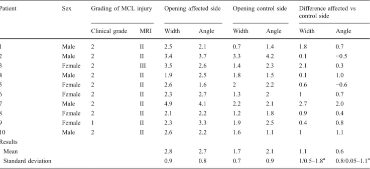
Table 2 Clinical and MRI grading of medial collateral ligament (MCL) injuries and measurements of medial joint opening in all 10 patients
Patient Sex Grading of MCL injury Opening affected side Opening control side Difference affected vs
control side
Clinical grade MRI Width Angle Width Angle Width Angle
1 Male 2 II 2.5 2.1 0.7 1.4 1.8 0.7 2 Male 2 II 3.4 3.7 3.3 4.2 0.1 −0.5 3 Female 2 III 3.5 2.6 1.4 2.3 2.1 0.3 4 Male 2 II 1.9 2.5 1.8 1.5 0.1 1.0 5 Female 2 II 2.6 1.6 2 2.2 0.6 −0.6 6 Female 2 II 2.3 2.7 1.3 2 1 0.7 7 Male 2 II 4.9 4.1 2.2 2.1 2.7 2.0 8 Female 2 II 2.1 2.2 1.2 1.8 0.9 0.4 9 Female 1 II 2.3 3.3 1.9 2.5 0.4 0.8 10 Male 2 II 2.6 2.2 1.6 1.1 1 1.1 Results Mean 2.8 2.7 1.7 2.1 1.1 0.6 Standard deviation 0.9 0.8 0.7 0.9 1/0.5–1.8a 0.8/0.05–1.1a
Joint opening is defined as the difference between measurements at maximal and minimal opening of the medial knee joint space. Width is expressed in mm. Angle is expressed in degrees
a
examination of joints, which involves an examiner interaction in the scanner, and the simultaneous acquisition of MR images has been confined to low-field open MRI systems [3,13]. In the present study, we used a 1.5 T MRI system equipped with a short-length, large-bore magnet that allows examiner access to patients while they are being scanned, as well as the acquisition of dynamic images at high temporal and spatial resolution. The results of our study suggest that this equipment may enable the quantification and therefore objective assessment of medial joint instability in patients with acute ligamentous knee injuries. In the present study, the objective was simply to determine whether dynamic MR imaging simultaneous to physical examination is capable of detecting differences in affected and contralateral tibiofemoral joint openings in patients with MCL injuries. In the future, it may be possible to utilize these techniques to further stratify patients with different clinical grades, and to elucidate the relationship between specific morphological lesions and abnormal joint kinematics.
In our study, the average difference between maximal and minimal medial joint opening was 1.1 mm greater in the affected knee than in the intact contralateral side. The average side-to-side difference was less pronounced when the angle approach was applied. By using this latter method, the contralateral joint opening was even slightly greater than in the injured knee in 2 patients. This may be explained by an enhanced susceptibility of angle measure-ments to through-plane motion artifacts. Even though we used a dynamic protocol, which enables the examiner to adjust an out-of-plane movement immediately, position displacement will inevitably occur during the physical examination. However, for both the angle and joint space width measuring methods, there was a statistically significant difference
between measurements obtained from the affected joint and those from the intact knee.
In the orthopedic literature, the clinical classification of the medial knee joint laxity is largely based on a three-point scale [6, 14, 15]. Joint opening less than 5 mm is categorized as a grade 1 laxity. A grade 2 injury is defined as medial joint opening in the range of 6–10 mm, and a grade 3 as opening greater than 10 mm on clinical examination. This grading system is thought to reflect the degree of morphological damage to the medial compart-ment. However, to our knowledge, a systematic investiga-tion of these numbers, confirming the associainvestiga-tion between the clinical grading of joint opening and the extent of structural damage, is not available. Kennedy et al. [16] evaluated medial and anterior instability both in normal and injured knees by using stress radiographs. They reported the normal medial knee laxity to be within the upper limit of 3.5 mm while the laxity in injured knees ranged between 3 and 8.5 mm. Their values obtained from normal knees are in agreement with the ranges of joint opening we observed in intact contralateral knees (0.7–3.3 mm). In contrast, the range of joint opening in affected knees (1.9–4.9 mm) was considerably smaller in our study. As a consequence, we noted a smaller side-to-side intrasubject difference in joint opening, averaging 1.1 mm. However, the findings pre-sented by Kennedy and colleagues [16] are not entirely comparable to those from the current study. In their study, valgus force was applied through a testing apparatus, instead of an examiner, which may produce a larger amount of force to the joint. Moreover, no information about the degree of MCL damage is provided in their article. In other investigations, the medial joint opening was measured in preoperative patients under anesthesia by using stress radiographs [14, 15, 17]. The authors of these studies reported medial joint opening values from 7 mm in isolated grade 3 MCL injuries [14] up to 16 mm in combined ligament injuries [17]. Although there are meaningful differences between the values presented by these inves-tigators and our findings, it is difficult to reliably compare our results with these previous studies. Physical examina-tions performed under anesthesia, which results in the relaxation of secondary joint stabilizers and the elimination of pain-related contractions, can be expected to lead to wider joint opening.
The majority of patients in our study had a grade 2 MCL injury. Only 1 patient was diagnosed with a clinical grade 1 injury whereas the static morphological MR imaging showed signs of grade 2 injury in that patient. The joint opening values in this patient with a clinical grade 1 injury lay within the same range as those found in dynamic MRI studies from other patients. A possible explanation for the low frequency of patients with minor injuries in our study is that these patients might attend hospital care less frequently.
Fig. 4 Box plots demonstrate side-to-side differences in joint space width (in millimeters) and opening angles (in degrees). The side-to-side differences were greater for the joint space width than for angle measurements. The box represents the 25th and 75th percentiles with the median (line across the box) and mean (square) inside. The whiskers show minimum and maximum values
On the other hand, through the design of our study, patients with grade 3 injuries were likely to be excluded. Grade 3 injuries, which indicate a completely torn MCL, are known to be associated with an injury of the ACL in nearly 80% of
cases [10]. Patients with gross signs of cruciate ligament injuries at the initial physical examination were excluded since the goal of the current investigation was to assess solely the kinematic model of MCL injuries.
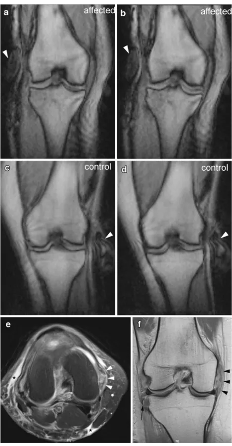
Fig. 5 Dynamic and morphological MRI in a 40-year-old woman. Physical examination revealed a grade 2 medial collateral ligament (MCL) injury of the right knee, whereas MR images depicted a complete rupture of the MCL (grade III). a–d Oblique coronal MR images were acquired with a 2D FLASH sequence (TR/TE, 6.6/2.75; flip angle, 20°) while valgus stress was being applied to the knee joint (note the hand of the examiner at the knee, arrowheads). Images show a minimal joint opening on the affected side, b maximal opening on the affected side, c minimal opening of the contralateral (control) side, and d maximal joint opening of the contralateral (control) side. The difference in width of the medial joint space between minimal and maximal opening was 3.5 mm in the affected knee and 1.4 mm on the contralateral side. e Axial T2-weighted fat-suppressed MR image (4,540/63) shows extensive high signal intensity throughout the transverse section of the thickened MCL (arrowheads). Diffuse edema can also be seen in the subcutaneous tissue (asterisks). f Coronal intermediate-weighted MR image (4,130/43) shows extensive high signal intensity in the thickened MCL
(arrowheads). The ligament appears completely discontinuous (grade 3 injury). The avulsed fragment at the lateral aspect of the proximal tibia indicates a Segond fracture (arrow)
We acknowledge several limitations to our study. Most importantly, the physical examination cannot be considered a reference standard because of the subjectivity of the test. However, triage decisions as to whether further tions are necessary are based on initial physical examina-tion. The intact contralateral knee may act as a more reliable control, since the right–left differences are reported to be as low as 12% for varus–valgus tests [18]. Another limitation is the lack of a surgical gold standard for determining the true grade of MCL injuries. The study is further limited by the small number of patients examined
and the inclusion of mainly intermediate grade MCL injuries. The adjustment for potential confounding factors such as sex, height, or weight was not possible because of the small number of subjects. Physiological shifts, such tibial rotation during the examination, may also affect the accuracy of measurements. It should also be mentioned that the potential utility of functional joint imaging must be weighed against the extra time and effort necessary to physically examine patients with MCL injuries. In some cases, this extra burden may mitigate against use in a routine clinical setting. Another limitation with the present
Fig. 6 Dynamic and morphological MRI in a 17-year-old boy. Physical and MRI examination revealed a grade 2 MCL injury of the right knee. a Dynamic 2D FLASH MR images (TR/TE, 6.6/2.75; flip angle, 20°) obtained in the oblique coronal plane show the difference in width (4.9 mm) between minimal (left image) and maximal (right image) joint opening in the affected knee. The width of the medial joint space is defined by a line perpendicular to the tangent along the cortex of the medial and lateral femoral condyles. b Dynamic 2D FLASH MR images (TR/TE, 6.6/2.75; flip angle, 20°) obtained in the oblique coronal plane show the difference in opening angles (4.1°) between minimal (left image) and maximal (right image) joint opening in the affected knee. The opening angle of the medial joint space is defined by a tangent connecting the femoral condyles and a line along the tibial plateau. c Axial T2-weighted fat-suppressed MR image (4,540/63) demonstrates high signal intensity around the slightly thickened MCL (arrowheads), which is consis-tent with a partial ligamentous tear (grade II injury). d Coronal intermediate-weighted MR image (4,30/43) shows high signal in-tensity in the deep portion of the thickened MCL (arrowheads). However, superficial fibers appear intact, indicating a partial-thickness injury (grade II)
study is that relatively small differences in joint opening between injured and contralateral knees were observed. These narrow differences may hinder the establishment of a reliable cut-off limit to distinguish between normal and injured knees. Finally, readers were unavoidably aware of the injured side because changes in and around the damaged MCL were conspicuous on dynamic MR images. This knowledge might have introduced an interpretation bias with regard to measurements.
In summary, dynamic MR imaging with simultaneous physical examination is feasible and enables the quantifi-cation of side-to-side differences in patients with abnormal joint kinematics due to MCL injuries. The unique ability to combine biomechanical with morphological imaging makes MR imaging of joint kinematics ideal for assessing and monitoring response to treatment in musculoskeletal disorders.
This study was performed without funding.
References
1. Miller RJ. Wrist MRI and carpal instability: what the surgeon needs to know, and the case for dynamic imaging. Semin
Musculoskelet Radiol. 2001;5(3):235–40.
2. Schmitt R, Froehner S, Coblenz G, Christopoulos G. Carpal
instability. Eur Radiol. 2006;16(10):2161–78.
3. Beaulieu CF, Hodge DK, Bergman AG, Butts K, Daniel BL, Napper CL, et al. Glenohumeral relationships during physiologic shoulder motion and stress testing: initial experience with open MR imaging and active imaging-plane registration. Radiology. 1999;212(3):699–705.
4. Brossmann J, Muhle C, Schroder C, Melchert UH, Bull CC, Spielmann RP, et al. Patellar tracking patterns during active and passive knee extension: evaluation with motion-triggered cine MR imaging. Radiology. 1993;187(1):205–12.
5. Muhle C, Brinkmann G, Brossmann J, Wesner F, Heller M.
Kinematic MR imaging of the ankle—initial results with ultra-fast
sequence imaging. Acta Radiol. 1997;38(5):885–9.
6. Grood ES, Noyes FR, Butler DL, Suntay WJ. Ligamentous and capsular restraints preventing straight medial and lateral laxity in intact human cadaver knees. J Bone Joint Surg Am. 1981;63 (8):1257–69.
7. Warren LF, Marshall JL. The supporting structures and layers on the medial side of the knee: an anatomical analysis. J Bone Joint
Surg Am. 1979;61(1):56–62.
8. Dallalana RJ, Brooks JH, Kemp SP, Williams AM. The epidemiology of knee injuries in English professional rugby union. Am J Sports
Med. 2007;35(5):818–30.
9. Morgan BE, Oberlander MA. An examination of injuries in major league soccer. The inaugural season. Am J Sports Med. 2001;29
(4):426–30.
10. Fetto JF, Marshall JL. Medial collateral ligament injuries of the knee:
a rationale for treatment. Clin Orthop Relat Res. 1978(132):206–18.
11. Hughston JC, Andrews JR, Cross MJ, Moschi A. Classification of knee ligament instabilities. I. The medial compartment and
cruciate ligaments. J Bone Joint Surg Am. 1976;58(2):159–72.
12. Schweitzer ME, Tran D, Deely DM, Hume EL. Medial collateral ligament injuries: evaluation of multiple signs, prevalence and location of associated bone bruises, and assessment with MR imaging. Radiology. 1995;194(3):825–9.
13. Logan MC, Williams A, Lavelle J, Gedroyc W, Freeman M. What really happens during the Lachman test? A dynamic MRI analysis
of tibiofemoral motion. Am J Sports Med. 2004;32(2):369–75.
14. Ballmer PM, Jakob RP. The non operative treatment of isolated complete tears of the medial collateral ligament of the knee. A
prospective study. Arch Orthop Trauma Surg. 1988;107(5):273–6.
15. Indelicato PA. Non-operative treatment of complete tears of the medial collateral ligament of the knee. J Bone Joint Surg Am.
1983;65(3):323–9.
16. Kennedy JC, Fowler PJ. Medial and anterior instability of the knee. An anatomical and clinical study using stress machines. J
Bone Joint Surg Am. 1971;53(7):1257–70.
17. Sawant M, Narasimha Murty A, Ireland J. Valgus knee injuries: evaluation and documentation using a simple technique of stress radiography. Knee. 2004;11(1):25–8.
18. Bryant JT, Cooke TD. Standardized biomechanical measurement for varus-valgus stiffness and rotation in normal knees. J Orthop Res. 1988;6(6):863–70.