HAL Id: in2p3-00704389
http://hal.in2p3.fr/in2p3-00704389
Submitted on 10 Dec 2013
HAL is a multi-disciplinary open access
archive for the deposit and dissemination of
sci-entific research documents, whether they are
pub-lished or not. The documents may come from
teaching and research institutions in France or
abroad, or from public or private research centers.
L’archive ouverte pluridisciplinaire HAL, est
destinée au dépôt et à la diffusion de documents
scientifiques de niveau recherche, publiés ou non,
émanant des établissements d’enseignement et de
recherche français ou étrangers, des laboratoires
publics ou privés.
Machine Protection System for the SPIRAL2 Facility
M.H. Moscatello, C. Berthe, C. Jamet, G. Normand
To cite this version:
M.H. Moscatello, C. Berthe, C. Jamet, G. Normand. Machine Protection System for the SPIRAL2
Facility. International Particle Accelerator Conference - IPAC’12, May 2012, New Orleans, United
States. pp.2612-2614, 2012. �in2p3-00704389�
MACHINE PROTECTION SYSTEM FOR THE SPIRAL2 FACILITY
M-H. Moscatello, C. Berthe, C. Jamet, G. Normand, GANIL, Caen, France
Abstract
The phase 1 of the SPIRAL2 facility, extension project of the GANIL laboratory, is under construction.
The accelerator is mainly composed of a normal conducting RFQ and a superconducting linac. One of its specificities is to be designed to accelerate high power deuteron and heavy ion beams (40-200kW), and medium intensity heavy ion beams as well (a few kW).
The associated Machine Protection System, has thus to be able to control and protect the accelerator for a very large range in terms of beam intensities and beam powers.
This paper presents the technical solutions chosen for this system and the present status of its construction.
INTRODUCTION
The SPIRAL2 facility under construction at Ganil will extend the possibilities for experimental nuclear physics towards more exotic beams [1].
The primary stable beams (deuterons, protons, light and heavy ions) accelerated by the Linac will range from a few 10 μA to 5 mA in intensities, and from 0,75 A.MeV up to 14,5A.MeV for heavy ions, 20 A.MeV for deuterons and 33 MeV for protons in energies.
The Machine Protection System (MPS) has thus to be designed to monitor a very large beam power range: a few 100W up to 200 kW.
MAIN FUNCTIONS OF THE MACHINE
PROTECTION SYSTEM
The main functions of the SPIRAL2 Machine Protection System are the following:
• Protect the beam tubes and insertable devices (slits, faraday cups, targets,…) from beam thermal damages
• Control the operating range of the facility
• Control the accelerator device activation due to beam losses (beam losses limited to 1W/m for D+ beams) • Ensure a reinforced protection of the beam dumps
and targets, which all have their own protection system.
THERMAL CALCULATIONS AND
RESPONSE TIMES
Thermal calculations have been performed in order to: • Evaluate the response time necessary in case of
instantaneous high beam losses
• Calculate the thresholds under which permanent beam losses are acceptable.
Response Times for Beam Cut
The response time is calculated in function of the various material temperature increases due to beam losses, and the operation temperatures must remain much
below the fusion temperature, in order not to degrade the material characteristics (usually, the thermal stress limit is considered [2]).
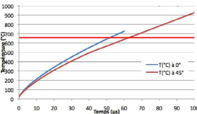
Response times for a 20A.MeV, 5mA, 200kW deuteron beam, lost on an aluminum chamber, are presented in Fig. 1, for two different angles of beam incidence; the limit operation temperature for aluminum is defined around 600°C.
A maximum of 50μs response time is calculated for aluminum chambers, while a maximum of 35μs response time is obtained for stainless steel chambers, for which a limit operation temperature of 1000°C is considered [3].
Figure 1: Response time for a 20A.MeV, 5mA, 200kW deuteron beam loss on aluminum chamber, for 2 different beam incidence angles.
Thresholds for Permanent Beam Losses
Thermal calculation in stationary and transitory modes are in progress, in order to evaluate the permanent beam losses acceptable on the various components of the accelerator like beam tubes, cavities, diagnostics, etc…
The specific mode with slow chopper has to be simulated, in particular for the extreme case of low mean intensity with high peak current [4].
The average permanent beam loss acceptable will be around a few tens of Watts, both on Aluminum and Stainless Steel chambers [5].
ARCHITECTURE OF THE MACHINE
PROTECTION SYSTEM
The SPIRAL2 Machine Protection System is based on two technical subsystems, as presented in Fig. 2:
• One dedicated to thermal protection, which requires a fast electronic protection system
• One dedicated to enlarged protection, which is based on robust technics, like PLCs or hard wired system, as it controls the operation domain of the facility from the safety point of view (beam intensities and energies), and the integrity of the various beam dumps and targets, among which actinide targets. This second system has much less constraints in
WEPPD044 Proceedings of IPAC2012, New Orleans, Louisiana, USA
ISBN 978-3-95450-115-1 2612 Copyright c○ 2012 by IEEE – cc Cr eati v e Commons Attrib ution 3.0 (CC BY 3.0) — cc Cr eati v e Commons Attrib ution 3.0 (CC BY 3.0)
07 Accelerator Technology and Main Systems T23 Machine Protection
terms of response times, situated in the millisecond to second time range.
Thermal Protection System
The thermal protection system is constituted of three main components:
A PLC which:
• Coordinates the machine mode changes
• Verifies the MPS hardware configuration through the Run Permit System (RPS). The Run Permit system enables to define in a secure way the Machine Mode. One Machine Mode corresponds to the choice of one beam type, one beam path along the accelerator and one beam power. These parameters are defined through a secure system based on hard wired keys [6]
• Activates or inhibits the monitoring equipments • Prevents from potential beam losses with slow beam
cuts, by controlling all ancillary systems like cryogenics, vacuum, etc…
• Protects insertable equipment from beam damages with slow beam stop
A fast electronic protection system, which protects the beam chambers from direct beam damage, and activates a fast beam cut through the use of the low energy beam line slow chopper. It receives the alarms from all the beam diagnostics, like loss rings and sleets, beam loss monitors, beam profile monitors, intensity measurements with
ACCT and DCCT, beam position monitors, time of flight monitors for energy measurements [7]. It sends then an order of beam cut to the Beam Time Structure Control Electronic, which commands the slow chopper, and to the RFQ if necessary in case of slow chopper failure, as shown in Fig. 2.
The control system manages the various detection thresholds, and the operator interface.
Enlarged Protection System
It is essentially a simple and secured system, based either on a PLC or a hard wired system. The specification of the system is in progress, and the final technical choice will be fixed soon. This system controls:
• The radiation produced by beam losses • The operating range of the facility • The beam dump and target integrity
It receives the alarms from beam loss monitors, beam intensity and energy diagnostics, beam dump and targets control parameters. It activates the beam cut through commands onto safe and slow beam stops like beam stops in low energy beam lines or ion source RF stops.
BEAM DIAGNOSTIC ALARM
MANAGEMENT SYSTEM
Beam diagnostics are distributed along the accelerator, and most of them are non interceptive, in order to control continuously beam parameters and beam losses [7]. Figure 2: Functional Scheme of the SPIRAL2 Machine Protection System, with its two sub-systems: Thermal Protection and Enlarged Protection.
Proceedings of IPAC2012, New Orleans, Louisiana, USA WEPPD044
07 Accelerator Technology and Main Systems T23 Machine Protection ISBN 978-3-95450-115-1 2613 Copyright c○ 2012 by IEEE – cc Cr eati v e Commons Attrib ution 3.0 (CC BY 3.0) — cc Cr eati v e Commons Attrib ution 3.0 (CC BY 3.0)
Alarm Management System
The beam diagnostic alarm management system is based on a fast electronic card, which receives for inputs, alarms from the various diagnostics, that are then summated on an electronic summation card, which sends the order of beam cut to the ECSF and RFQ, like shown in Fig. 3.
Figure 3: Beam diagnostic alarm management system.
Threshold and Alarm Management
The thresholds for beam loss detection have to be recalculated for each beam, due to the specificity of SPIRAL2, which accelerates a large range of beams, with various intensities and energies. The general control system calculates these thresholds when preparing the beam parameters, and writes them on dedicated electronics cards.
The reset of the alarms is automatically done by the PLC, while memorization of all the alarms is made in the threshold management electronic cards and then addressed to the general control system for information.
BEAM LOSS MEASUREMENTS
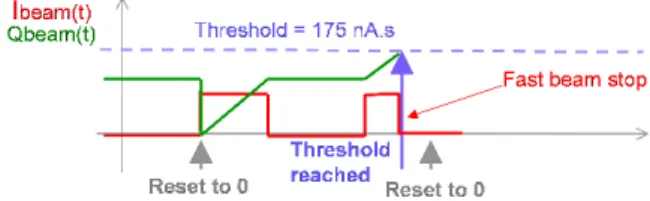
The beam loss measurements processed in the thermal protection system (fast), are integrated on a given period of time, like presented in Fig. 4.
This solution, inspired from that used in GSI [8], allows response times to be function of beam loss levels, and thus permits technical solution more simple in terms of diagnostic signal management electronics.
This comes down to use a beam charge threshold rather than a beam intensity threshold. If one considers a threshold equal to 175 nA.s, it means that:
• For a 200kW 20A.MeV beam loss (5mA), response time is 35μs
• For a 50W 20A.MeV beam loss (1,25μA), response time is 140ms
Figure 4: Principle of beam loss measurement integration. Nevertheless, the effect of beam time structure on the temperature variation has to be evaluated and this study is currently in progress.
CONCLUSION
The SPIRAL2 Machine Protection System is currently under design. PLCs and fast electronic cards are under preliminary design, for a realization scheduled in 2013. The technical complexity of the SPIRAL2 system is directly linked to the large variety of accelerated beams, in terms of intensities (several orders of magnitude) and energies, and to the beam time structure, which may vary in a very large bandwidth. The MPS will have to be in operation for the second semester of 2013, for the commissioning of the SPIRAL2 injector.
REFERENCES
[1] E.Petit, “Progress of the SPIRAL2 project”, IPAC2011, San Sebastian, Spain, p.1912 (2011). [2] C.Sibley, “Machine Protection Strategies for high
power accelerators”, IPAC2003, Portland, USA, p.607 (2003).
[3] F.Pellemoine, “Preliminary thermal calculation”, SPIRAL2 Internal Report, ref. EDMS I-027629V1. [4] A.Caruso, “the LEBT chopper for the SPIRAL2
project”, IPAC2011, San Sebastian, Spain, p.1731 (2011).
[5] F.Launay, “Thermal calculation for SPIRAL2 permanent beam losses”, http://pro.ganil-spiral2.eu/events/sp2/spiral2-week-2012.
[6] C.Berthe, “Machine Modes implementation and Run Permit System”, SPIRAL2 Internal Report, ref. EDMS I-027794V2.
[7] C.Jamet, “Injector diagnostics overview of SPIRAL2 accelerator”, DIPAC 2007, Venice, Italy, p.304 (2007).
[8] H.Reeg, “Machine Protection by active current-transmission control at GSI-UNILAC”, EPAC 2006, Edinburgh, Scotland, p.1025 (2006).
WEPPD044 Proceedings of IPAC2012, New Orleans, Louisiana, USA
ISBN 978-3-95450-115-1 2614 Copyright c○ 2012 by IEEE – cc Cr eati v e Commons Attrib ution 3.0 (CC BY 3.0) — cc Cr eati v e Commons Attrib ution 3.0 (CC BY 3.0)
07 Accelerator Technology and Main Systems T23 Machine Protection