Designing the Sugar Cane Charcoal Extruder
ByDexter W. Ang
Submitted to the Department of Mechanical Engineering In Partial Fulfillment of the Requirements for the Degree of
Bachelor of Science in Mechanical Engineering at the
MASSACHUSETTS INSTITUTE OF TECHNOLOGY June 2005
© Dexter W. Ang. All rights reserved.
l _,1 I i , . _ 1
I ne author nereby grants to Mil I permission to reproduce
And to distribute publicly paper and electronic Copies of this thesis document in whole or in part.
~~~~~~~~~~~~~~~~~~~~~~~~~~~~~~~~~~~~~~~~~~~~~~~~~~~~~Signature of Author: g ~~~~~~~~~~~~~,
Signature of Author:
DEtint Weh nical Engineering
/ \ May 6, 2005
\ --I
Certified by:
- v - ~ David R. Wallace Esther and Harold E. Edgerton Associate Professor of Mechanical Engineering Co-Director MIT CADlab Thesis Supervisor
Accepted by:
Ernest Cravalho Professor of Mechanical Engineering Chairman of the Undergraduate Thesis Committee
ARCHIVES AASSACHUSETTS INSTITUTE OF TECHNOLOGY JUN 0 8 2005 LIBRARIES R
Designing the Sugar Cane Charcoal Extruder
ByDexter W. Ang
Submitted to the Department of Mechanical Engineering In Partial Fulfillment of the Requirements for the Degree of
Bachelor of Science in Mechanical Engineering
Abstract
The Sugar Cane Charcoal Extruder compresses carbonized sugar cane into charcoal briquettes. that are environmentally-friendly and comparable to wood charcoal in burn performance, cost,
and durability. Originally developed in the fall semester of 2004 in the MIT course 2.009, Product Engineering Processes, the extruder is designed for use in Haiti where wood charcoal
constitutes up to a seventh of a family's expenditures. For a nation without a widespread electric grid such as Haiti, a locally manufacturable, affordable, and family-operated charcoal extruder is an effective method to introduce alternative energy into the economy.
This thesis documents the past developments of the extruder and presents an improved design that is more portable, more robust, and less expensive to build than the original versions. The new design loads the bagasse and binder directly into the feedscrew and compresses the mixture using threads of decreasing pitch. Evaluations of design successes and failures are provided as well as recommendations for future development.
Contents
Introduction...4
Background...4
The Sugar Cane Solution ... 5
Design Goals ... 6
Generations of D esign ... 8
Experim enting w ith Extrusion ... 9
M ockup M odel ... 9
Vertical M ockup M odel ... 11
Finalized 2.009 M odel . . . ...13
Extruder Redesign ... 16
Directions for Construction ... 21
Performance...27
Concluding Analysis ... 28
A cknow ledgem ents . . . ...31
Introduction
This thesis is focused on the design process of the sugar cane charcoal extruder. It presents the motivation for creating the extruder and the construction stages that demonstrate the feasibility of extruding sugar cane briquettes. The thesis begins with background information on the extruder target market of Haiti and explains how sugar cane has the potential to transform the energy economy of this nation. Design goals for an extruder to capture this alternative energy are described as well as the logistical concerns affecting how successfully the extruder impacts and spreads throughout the Haitian community. The following sections illustrate the
development stages of the extruder with emphasis on the problems encountered and the
modifications implemented to address them. The thesis concludes with a summary of the design process and an analysis of the extruder against performance expectations determined at the onset of the project.
Background
The current process for creating cooking fuel in Haiti requires cutting down trees and carbonizing them in dirt trenches1. The resultant wood charcoal is then sold to individual families who spend approximately one seventh of their annual income on this fuel for cooking2. Haiti is already 97% deforested and becoming more so as wood charcoal is the primary cooking fuel available in the market3.
future of the Haitian economy depends on distributing a sustainable source of fuel that is both easily accessible to rural villagers and no more costly than wood charcoal.
The Sugar Cane Solution
Sugar cane is an abundant cash crop in Haiti that is harvested for its sugar at the rate of nearly six million tons per year4. The byproduct of sugar extraction is called bagasse and has no direct use or value. Unprocessed bagasse is not an effective energy source and bums both uncleanly and inefficiently. However after drying, bagasse can be carbonized in a kiln to produce a material that has the burning capability of wood charcoal. Molding that material into briquettes creates a portable and durable fuel. Similar in size to commercial charcoal in the United States, bagasse briquettes have the potential to replace wood charcoal3.
However without a standardized forming process, hand-pressed briquettes are easily broken and highly inconsistent in shape and size. A strong compression force and liquid starch can solve this problem by binding the bagasse.
In the fall 2004 semester of the undergraduate mechanical engineering course 2.009: Product Engineering Processes, Edgerton Instructor Amy Smith proposed the challenge of creating a machine to perform this compression. A team of 15 students were charged with pursuing this project and created multiple mockup and finalized versions of the machine.
Figure 1: Sugar Cane Charcoal Extruder created in 2.009
As shown in Figure 1, the finalized extruder has three primary parts: the hopper which is what you load the bagasse into, the screw which both feeds the bagasse into the pipe and extrudes it,
and the pipe which shapes the briquettes. Material is loaded into the extruder on the lip of the hopper, and the user turns the wheel. The screw is turned to drive bagasse into the pipe where it builds up at the end of the screw. As the material builds up within the pipe, the bagasse is
compressed and pushed out of the pipe. The operation is continuous, and the briquettes are cut as they exit.
Design Goals
Throughout the design process, the primary goal of the extruder has been to produce briquettes that are comparable to wood charcoal in burning performance and durability at a cost affordable
for rural Haitian families. As the motivation for designing the extruder comes from a desire to create an alternative and self-sustaining form of energy and not financial gain, none of the
extruder designs have been patented. Similiarly, factors relating to building costs and feasibility of local manufacturing were also considered to encourage replicability and widespread
distribution.
Being considerate of the costs of building the extruder determined many of the methods used to construct the various designs. Based on interviews with Amy Smith, an upper limit of a $100 US dollars was imposed as the maximum amount that a Haitian family could invest in an extruder. The extruder should produce enough charcoal to pay for itself in a year. Even though sugar cane waste is currently free to obtain in vast quantities, it is anticipated that success of our extruder would create demand for the waste and lead to a market for the buying and selling of bagasse and bagasse briquettes. This market would interfere with the existing wood charcoal market, and the expanded charcoal supply could translate to a general decrease in charcoal prices. Considering the indeterminate nature market prices, the target cost of the extruder was
lower than the $100 limit to allow for additional bagasse procurement and building costs. The material and building costs of each model of the extruder have not exceeded $75 US dollars.
A requirement parallel to the costs of building is that the extruder be easily fabricated in Haiti at a low cost. The materials there are limited to steel from oil drums, rebar, plumbing parts, and
scrap metal. Haitian metal workers have no automated equipment, but are highly skilled in cutting, gas welding, and bending. Figure 2 demonstrates typical Haitian metal working capabilities.
Figure 2: Haitian hammering an oil drum
Generations of Design
The extruder has gone through four distinct generations of design and revision. From the two mockups developed at the beginning of 2.009 to the current design that is being constructed, each version improves on the previous model and also presents areas for further development. The original mockup investigated the extrusion process and revealed the complex flow
characteristics of bagasse. The vertical mockup produced successfully compressed briquettes and introduced the difficulties of feeding bagasse from the hopper into the pipe. The 2.009 extruder created briquettes that were comparable to wood charcoal but was also sensitive to the type of bagasse loaded. The most recent extruder described within this thesis departs from the previous versions for more robust and simplified operation. This design investigates different
methods of feeding and extrusion and can be constructed from the contained directions. It was successful at revealing more about the extrusion process but unsuccessful at producing
Experimenting with Extrusion
Once extrusion was finalized as the primary approach to making charcoal, the 2.009 team tested whether bagasse could be compressed using this method. To accomplish this, we searched for commercial products that emulated the process and output we desired in our future extruder. The most similar products were hand-powered meat grinders which extruded ground meat with texture and variability comparable to bagasse mixed with binder. After buying the small meat grinder shown in Figure 3, we tested it using commercially available charcoal that was crushed into the texture that we expected bagasse to have. The proof-of-concept was successful in demonstrating that the grinder could extrude charcoal; however, we discovered that feeding the charcoal into the grinder was difficult and required constant downward pressure.
Figure 3: Using a meat grinder to demonstrate extrusion as a viable compression method
Mockup Model
The next step in following through with the extrusion design was creating a mockup model. We used pipe, wood, and a commercially purchased earth auger bit to represent the meat grinder screw. The dimensions of the model were determined from the size of the output we hoped to
create and standardized the 2" screw and pipe as the desired molding size for our briquettes. Two mockup versions are shown in Figures 4 and 5.
Figure 4 & 5: First and second mockup models
For the hopper, we decided to develop a more open and higher capacity design than the meat grinder. We mimiced the horizontal layout of the grinder and built the hopper to surround the screw and directly feed bagasse into the pipe. We created bearings for the screw from two wood blocks with holes the width of the screw shaft. Ideally, the screw would be fed from all sides, and bagasse would easily flow into the pipe for compression. This hypothesis turned out to be incorrect as the material built up on the inside wall of the hopper instead of being driven into the pipe. The screw was highly ineffective at feeding. Even when material flowed into the pipe, it did not exit significantly compressed. We tried to combat that problem by installing multiple nozzles onto the end of the pipe in hopes that a decreasing output diameter would increase the pressure forming the extruded briquettes. However, when experimenting with both steep and very shallow nozzle designs, the forces required to turn the screw became so great that our model broke in multiple places. The extruder did not output material in an effective manner, and we concluded that we could not depend on a nozzle as the primary method of compression.
The lessons learned from the mockup model were that bagasse did not feed easily into the screw, that the forces occurring within the pipe require the extruder to be built with stronger materials than wood and screws, and that even a shallow decrease in the diameter of the pipe resulted in tremendous buildup. In particular, this model introduced the problem of ineffective feeding, a problem that would persist until our final design.
Vertical Mockup Model
The next model was the vertical extruder shown in Figures 6 and 7. We changed the orientation of the extruder for two reasons: to allow bagasse to flow freely into screw from all directions and to create a downward force on the bagasse to promote feeding.
Figure 6 & 7: vertical mockup model
The hopper was constructed with a steep angle to allow the bagasse to easily slide downward. However, even with this change, the bagasse did not slip well on the aluminum sheet hopper, and we had to use a metal rod to mix the bagasse to promote feeding. The continuous level of
intervention was frustrating and inefficient so we determined that some form of paddle should be fixed to the screw shaft to automatically mix bagasse within the hopper. We experimented with various open and closed paddle designs of differing sizes. We also changed the pipe to steel for increased strength and observed that briquettes extruded from this pipe were more compressed. From this discovery, we began to understand how the texture and roughness of the pipe affected the compression of the briquettes. Roughness leads to greater friction between the bagasse and the pipe to allow pressure to build up. As shown in Figure 8, the resulting briquettes were nicely compressed.
Figure 8: Briquette extruded from vertical mockup
We learned that, even with a streamlined vertical design, bagasse would not flow into the pipe without constant mixing and that, since friction within the pipe could compress the bagasse, the
fixed pitch screw was performing satisfactorily. We also felt that turning the screw in the vertical orientation was uncomfortable and decided that the handle should be angled for more natural operation. A method of cutting the exiting briquettes was needed as well and would be implemented in the next design.
Finalized 2.009 Model
The design that ultimately became our finalized original version focused on improving feeding and human operation. It had a number of new and modified features including: a decreasing diameter screw, a fixed mixing paddle, a larger hopper, a large base so the extruder could be used while standing, a large angled turning wheel, and a cutting spur to automatically cut the extrusion log into measured segments. Figure 9 depicts the critical components of the extruder that was presented in 2.009.
Figure 9: Finalized 2.009 extruder
Creating the screw required multiple generations of experimentation. The selected design was constructed by inserting a segment of the two inch screw into the larger shaft of a four inch screw. The threads were shaved down to smooth the step between the different screw diameters and begin within the hopper at a diameter of four inches and decrease to the two inch diameter along the hopper wall. The dynamic diameter was the most important factor affecting feeding effectiveness. This change, coupled with an open paddle to prevent the bagasse from settling against the hopper wall, translated to an efficient feedrate. There are also small spokes that protrude from the screw shaft to encourage mixing directly below the paddle. Each turn of the
wheel continually breaks up and stirs the bagasse to prevent build up along the walls and drives almost a full threadsworth of bagasse into the pipe. Figures 10 and 11 show the different screw diameters and selected design.
Figure 10 & 11: Handmade screw and screw used in finalized 2.009 extruder
The hopper was greatly increased in size to allow for long periods of uninterrupted operation. It can hold the amount of bagasse produced from a barrel of sugar cane which takes 15 to 20 minutes to extrude. The hopper was made by bending a sheet metal cone template. Since the hopper is angled, a lip was added to top edge to allow for easier loading. This feature was made by cutting a chord of the hopper and welding it back at a flared outwards angle.
All primary components of the extruder are welded. The pipe is attached to the hopper and the stand to transfer torques generated from extrusion directly to the stand. The stand has a large footprint and holds the hopper fully upright at a fixed angle. It is made of steel square stock and elevates the extruder for standing operation.
extruded bagasse into measured sections. This design was selected from a number of others because of its autonomous operation. The spur is attached near the end of the pipe and works by contacting the exiting bagasse. As the bagasse pushes on a spoke of the spur, the next spur is driven into the bagasse to cut it near the pipe opening. The length of each briquette is equal to the distance between the spokes. The spur shown in Figure 12 requires no maintenance and can be taken off for easy cleaning.
Figure 12: Cutting spur
The extruder presented at the conclusion of 2.009 satisfies most of the original product goals, and the briquettes extruded from it are usable as cooking fuel. However, this version of the extruder could be improved in many ways.
The extruder often requires a large amount of effort to operate. Due to inefficiencies in feeding and friction within the pipe, turning the wheel can become difficult and tiring.
The performance of the extruder varies significantly according to the texture of the bagasse used. While the bagasse used in 2.009 exits the extruder sufficiently compressed, actual Haitian
bagasse which is finer and grainier does not. The extrusion process must become more robust and efficient.
The total size of the extruder and stand should be reduced to increase portability as well as decrease material costs. The current hopper capacity is much greater than the largest load we poured in and can be decreased. Since the size of the frame is directly related to the size of the hopper, reducing the hopper size would result in significant space savings.
Because of the spinning action of the spur, the briquettes are cut at a slanted angle. These slanted edges are much weaker than the smooth cylindrical surface and are susceptible to crumbling and breaking. Another method of cutting should be devised to cleanly cut the briquettes at a right angle.
Last, this extruder as well as all previous versions must be loaded with bagasse that is already mixed with binder. While this has been acceptable, it requires a significant amount of
labor-intensive mixing before extrusion can even begin. Future designs should try to incorporate this mixing action into the extrusion process to increase the overall efficiency of the charcoal making process.
Extruder Redesign
The focus of this thesis is understanding how to improve the previous versions of the extruder. The approach used in redesigning the components of the extruder relies on using experience gained from previous successes and failures. From each generation of the hopper, screw, and
stand, a better understanding of the characteristic flow and dynamics of the bagasse was
developed. From the mockup, we determined that bagasse would not easily flow into the threads of a screw and that it would instead settle above the tunneling screw. We also learned that the bagasse was highly difficult to force through the decreasing diameter of a nozzle no matter how shallow the decline. From the vertical mockup, we discovered that gravity alone was not strong enough to drive the bagasse into a vertical pipe and that a paddle was needed to stir it. In the 2.009 presented form of the extruder, a complex screw and paddle was necessary for effective feeding, but the friction was so great to cause the wheel to be difficult to turn and simultaneously not high enough to compress the actual Haitian bagasse into durable briquettes. This version of the extruder also used commercially purchased parts for the bearings and screw instead of parts replicable by hand.
The question most central to addressing these problems is how to approach them. One approach would be to examine and solve each problem on the individual component level. For example, the feeding of the vertical extruder was improved upon by adding a paddle to the shaft of the screw. Another approach to extruder redesign is changing the fundamental operation of the extruder. For example, rather than depending on the roughness of the pipe to cause the bagasse to build up and become compressed, the screw could directly compress the bagasse within its threads through gradually decreasing pitch. Rather than try to build a better paddle to improve feeding bagasse into the pipe, bagasse could be directly fed into the pipe. The shift from
addressing individual problems to reexaming the holistic operation of the extruder is essential to producing the most streamlined process for compressing bagasse into briquettes.
that could be addressed through the first approach was limited, and only the portability and commercial parts issues were improved upon. The resulting model utilized a more succinct stand as well as a much smaller hopper as displayed in Figure 13. The bearing was redesigned using sheet metal and wood. However, the problems of feeding and compression, the most important issues affecting the operation of the extruder, could not be addressed without drastically altering the design.
Figure 13: Solidworks model comparing the sizes of a possible redesigned extruder to the hopper from the finalized 2.009 extruder
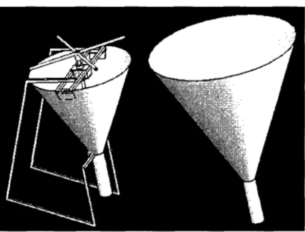
The second approach of rethinking the extruder in its entirety led to the following design shown in Figure 14. The new design incorporates a more modular configuration that isolates the operation of each step in the extrusion process. Instead of requiring already mixed bagasse and binder to be loaded into the hopper, dry bagasse is fed first and then mixed with the binder as the screw extrudes and compresses the bagasse. Figure 14 shows how the screw is loaded with bagasse through a slot cut into the pipe. The binder is added after the loading slot.
Figure 14: In the new design, bagasse is fed directly to the screw
The feeding rate of bagasse is regulated by the rate of screw turning, and the liquid binder can be easily controlled to match. By separating the two components into independent flows, the output charcoal is more tightly controlled in texture and consistency. As shown in Figure 15, bagasse is fed through the side slot, and binder flows in through a hole after the slot.
Figure 15: Solidworks model depicting primary components of the most current extruder design
Introducing the bagasse at a different location from the binder provides the additional benefit of improved feeding. Without binder making the the mixture sticky, bagasse feeds easily into the pipe. Charcoal is a natural lubricant and improves this flow. Once the bagasse is fed into the
pipe by the screw threads, the binder is added directly to the bagasse through a tube.
This design departs significantly from previous models in that there is no central hopper holding the bagasse and binder mixture. The pipe essentially serves the role of the hopper in which the bagasse is fed, mixed, and compressed by the screw in one step. Because of the screw design, compression does not come exclusively from the roughness of the pipe, but also from the decreasing pitch of the screw threads as illustrated in Figures 16 and 17. The increasing pressure from the gradually decreasing space crushes the mixture and ensures that the binder is squeezed throughout5. When the dense mixture reaches the end of the screw, it is already compressed and becomes more so as it builds up in the pipe. The build up is eventually driven outwards as material pushes from behind.
Figure 16 & 17: Redesigned screw made from sheet metal
The wheel is simplified to a four-spoke handle that is much smaller than the 26 inch diameter of the previous version. Similar to the other wheels, it is directly attached to the shaft of the screw and is angled at the same angle of the screw and pipe. Like the previous extruder, this angled wheel makes extrusion more comfortable for the user.
from aluminum and wood instead of the commercial bearings used in previous models. The purpose of the bearing is to absorb the thrust force generated from compressing the bagasse as well as to support the screw. Wood is used because of its firm but giving texture and is fitted between the aluminum walls. After extended usage of the bearing, it can be replaced
inexpensively. The length of the bearing is sufficiently long to keep the screw shaft in
alignment. While the wood handles the rotational torques, the aluminum walls endure the thrust force transferred from the set collars attached to the screw. The entire bearing assembly is tightly fit together to distribute the forces to the pipe. Unlike previous designs, all the forces are contained within the pipe so joints or welds do not become stressed.
Figure 18: Redesigned bearing made of wood and aluminum
A cutting spur can be attached to the end of the pipe; however, a more effective design is needed. Since the briquettes should have clean faces rather than the rough angled edges the spur
provides, the spur should be replaced with another automatic cutting mechanism.
The newest design of the extruder is comprised of the following components: screw, pipe, bearing, wheel, hopper, and stand. The dimensions used are for creating two inch diameter briquettes.
The screw is the most critical part of the extruder and the most difficult to build. It is created from a central shaft of ½2" steel and threads made from steel sheet metal with a thickness of
1/32". The shaft should be long enough to penetrate the bearing and threads as well as extend behind the pipe where the wheel is attached. This length depends on the number of revolutions and pitch of the threads and is 20 inches in the designed model. The threads are thin to be easily formed into screw helixes, but are also strong enough to handle the pressure created from
compressing the bagasse.
Since the pitch of the threads decreases along the screw, the diameters of the thread templates must also decrease in size. The measurements should create threads that when properly stretched fill the inside diameter of the pipe. For this model, thirteen rings were created with diameters decreasing from 2.163 inches to 2.016 inches. The first three rings are the same size as well as the last two. The corresponding decreasing pitch begins at 1.65 and decreases to .50 inches for a total screw compression ratio of 3.3. The sizes of the center holes are proportional to the outer diameters and decrease from .689 to .557 inches. As shown in Figure 19, there is a radial cut in each of the rings from the hole to the outside of the diameter to allow the rings to be joined in series.
Figure 19: The largest and smallest rings used to construct the screw
To stretch the rings to the correct pitch, a system of clamps is needed. First an initial hand stretch opens up the rings. Then two small C-clamps and a larger clamp is used. Examples of these clamps are displayed in Figure 20.
Figure 20: The clamps should be set up to stretch the rings a controlled distance
The small clamps grip the ends of the ring to the large clamp to keep them parallel as they are pulled away from each other. This step is important to create a uniform twist as well as ensure that the ends are straight to join to the surrounding rings. The clamps should be placed only at the top corners where the slot edge meets the inside diameter. As little material should be held
down to prevent the clamp from affecting the final twisted form; however the grip should be firm enough to withstand the stretching force. Figure 21 demonstrates the proper gripping location.
Figure 21: The ring should be gripped at the upper corner of the inside edge
Once the ring is clamped, the large clamp is gradually opened until the ring assumes the desired pitch. Due to springback, the pitch will be smaller than its clamped length. Springback varies according to the ring's size, thickness, and material, and a few rings should be tested to
determine the amount of over stretch needed to compensate for springback. Figures 22 and 23 illustrate the final form of a correctly stretched ring.
Once the rings are created, they are placed individually over the shaft beginning with the smallest ring at the end of the shaft. The ring is welded to the shaft. The next ring is placed behind in series, and the two ends are welded together. There should little if any overlap of the rings to keep the welds from protruding from the thread surface. The protrusions from the welds should be filed down for a smooth surface.
Once the screw is done, the bearing for the screw is created from two aluminum disks and a wood cylinder. These pieces are cut to the size of the inside diameter of the pipe. The aluminum disks should be thick enough for four holes to be tapped radially 90 degrees apart from each other. These holes will allow screws to be driven into the disks to hold the bearing and the screw within the pipe. Holes slightly larger than the diameter of the screw shaft are drilled through the centers of the disks. The wood cylinder should have a length roughly three times the diameter of the screw shaft. A hole with a diameter equal to the diameter of screw shaft is drilled axially through the center. The disks surround the wood tightly, and holes that match up to the holes in the disks should be driven into the pipe beginning an inch from one end.
A set collar is placed on the screw shaft directly behind the largest thread. The bearing is slid on next, and a second set collar is fitted against the other side of the bearing to keep it in place. The screw should be fixed axially but be able to rotate freely within the bearing.
Figure 24 shows the rectangular window cut into the pipe for bagasse to be fed into the threads. This window is a few inches from the end of the pipe to reveal the first two threads of the screw. It should be a narrower than the width of the pipe. The dimensions used in this model are four
inches by one and a half inches. Afterwards a small hole can be drilled through the pipe where binder flows in.
Figure 24: The side window allows bagasse to be fed directly to the screw
Once the screw and pipe are completed, a small hopper for the bagasse can be built for feeding. Unlike previous extruders, this hopper does not need to be an exact shape or size because there is no paddle within it and no significant forces are exerted on it. The hopper should fit over the slot in the pipe and have steep walls to encourage feeding. Figure 25 shows the hopper created for this model from sheet metal and duck tape.
A wheel can be constructed and added to the extruder. However, for this draft model, vice grips were used to turn the screw and were sufficient to demonstrate the operation of the extruder.
Once the extruder is clamped down to a table, it can be tested.
Performance
The new extruder was ultimately unsuccessful at extruding compressed briquettes but revealed several previously unknown properties of bagasse.
Dry bagasse fed very effectively into the screw even without the aid of a paddle or vertical orientation. Feeding was continuous with the screw turning and, unlike previous designs, did not require any intervention. Also, as discovered in earlier extruders and confirmed by this one, wet bagasse does not feed without a stirring paddle.
The primary difference between this design and previous ones is that this extruder is loaded with unmixed bagasse. Binder was introduced post-hopper through a hole in the pipe. However, it reached only the directly contacted bagasse and did not spread throughout the bagasse as
expected. The core bagasse remained completely dry and easily crumbled. When the binder hole was located a quarter inch from the end of the hopper, the binder did not mix with the extruding bagasse but rather the bagasse within the hopper became moist and then did not feed.
Using a decreasing pitch, even a slight one, seems to greatly increase the difficulty of turning the screw without significant compression. The dry bagasse did not originally extrude to the end of the screw so the screw was cut until the compression ratio of the threads decreased to about 1.2
instead of the original 3.3. Even with this level of compression, the screw was difficult to turn. When wet bagasse was used it did not reach the end of the screw, and the friction between the bagasse and the pipe grew to be so great that the screw could not be turned by hand. This increased difficulty could be a result of the increased work required to compress the bagasse within the threads.
Concluding Analysis
During brainstorming for the first version of the extruder, the 2.009 team assumed that the screw would be easy to turn and that there would be no problems feeding bagasse into the screw. While these assumptions were proven incorrect, each version of the extruder revealed more about the behavior of bagasse flow and compression. While the extruder design created for this thesis did not produce improved briquettes as hoped, it did provide deeper insight into the extrusion process.
The design revealed how the feeding ability of bagasse is strongly affected by its moisture. The slot in the pipe was an effective feeding method for dry bagasse and should be maintained for future designs because of its simplicity and ease of use. Other methods of introducing the binder to the bagasse should be investigated such as a separate hopper and slot for binder or a hollow shaft with holes for binder to contact bagasse from the inside.
Since the bagasse became stuck within the threads of the screw, the roughness of the screw could be a major factor gripping the bagasse and preventing it from extruding effectively. Solutions to this problem are to further smooth the surface and reduce the compression ratio of the screw.
However, since the threads are handmade and hand-welded, a relatively high level of roughness and inconsistency is inherent in the manufacturing process. It seems idealistic and perhaps unrealistic to expect a screw made by blacksmiths to be as smooth and precise as a commercially available one. If the tolerances for the extruder as so narrow as to make it difficult to correctly manufacture then the overall feasibility of producing a handmade, single family-owned extruder may not be worth its cost and effort.
For now, it seems that the screw is an effective vehicle to feed bagasse, but not to compress it. The original 2.009 screw design of a large and consistent pitch should be preserved, and other features of the extruder should be redesigned to further understand the extrusion process. The pipe inside texture and shape could be altered to increase friction and compression. Shallow nozzles can be experimented with as well as the length of the pipe after the screw. An effective design could be a very shallow nozzle that begins at the immediate end of the screw.
The broad goal of the project is to manufacture sugar cane briquettes at a widespread and self-sustaining level, and a portable extruder is only one way to approach this goal. The forces required to compress the bagasse to durable briquettes may be higher than can be achieved through human power. It may be that the most effective and successful method of doing this is not through handmade, hand-operated extruders but rather large scale commercial facilities.
However, the replicable handmade extruder was originally selected as a feasible business model because of its potential for impacting the energy economy of Haitian communities at a local level. This promise of bringing sugar cane briquettes to the people most in need of them
demands that the charcoal extruder not be abandoned without further research and testing to confirm it as an ineffective model.
Acknowledgements
Prof. David Wallace - Thesis Supervisor and 2.009 Course Instructor Instructor Amy Smith - Project Advisor
Steve Haberek- Welding Specialist in Pappalardo Lab Ken Stone - Director of MIT Hobby Shop
Additional Acknowledgements from 2.009
2.009 Blue Team - Dexter Ang, John Brewer, Panasaya Charenkavanich, Kevin Chen, Greg Fonder, Danny Hilton, Lynn Kamimoto, Matthew Kreuger, Shira Lee, Sheila Longo, Way Luu, Andres Pino, Andres Ramirez, Orlando Soto, Ben Su
David Meeker, Woodie Flowers - 2.009 Section Instructors Melissa Barbagelata - Mentor
Dick, Bob, Bob, Steve, Joe - Pappalardo Lab Staff Scott Spence - Central Machine Shop
Jamy Drouillard - Haitian Life Consultant Sugar cane supply companies
References and Resources
[1] Collie, Tim. "'We know that this is destroying the land, but charcoal is what keeps us alive'." 7 Dec 2003. South Florida Sun Sentinel. 2 May 2005.
<http://www.latinamericanstudies.org/haiti/charcoal.htm>
[2] Smith, Amy. Personal interviews. Nov 2004.
[3] Smith, Amy. "Fuel from the Fields." 22 Dec. 2003. Massachusetts Institute of Technology. 15 Apr 2005. <web.mit.edu/d-lab/portfolio/charcoal/
Fuel%20from%20the%20fields%20Website%20Draft.doc>
[4] Central Intelligence Agency. "CIA - The World Factbook -- Haiti." 21 Apr 2005. CIA. 2 May 2005. <http://www.cia.gov/cia/publications/factbook/geos/ha.html>
[5] Dray, R. F and Gregory, R. B.. "The History of Extruder Screw Design." 2005. R.Dray Mfg. Inc.. 23 April 2005. <http://www.rdray.com/extruder.htm>