HAL Id: hal-00842799
https://hal.archives-ouvertes.fr/hal-00842799
Submitted on 9 Jul 2013
HAL is a multi-disciplinary open access
archive for the deposit and dissemination of
sci-entific research documents, whether they are
pub-lished or not. The documents may come from
teaching and research institutions in France or
abroad, or from public or private research centers.
L’archive ouverte pluridisciplinaire HAL, est
destinée au dépôt et à la diffusion de documents
scientifiques de niveau recherche, publiés ou non,
émanant des établissements d’enseignement et de
recherche français ou étrangers, des laboratoires
publics ou privés.
Comparison of the effects of rolling resistance and
angularity in sheared granular media
Nicolas Estrada, Emilien Azéma, Farhang Radjai, Alfredo Taboada
To cite this version:
Nicolas Estrada, Emilien Azéma, Farhang Radjai, Alfredo Taboada. Comparison of the effects of
rolling resistance and angularity in sheared granular media. Powder and Grains 2013, 2013, Sydney,
Australia. pp.891-894. �hal-00842799�
Comparison of the effects of rolling resistance and angularity
in sheared granular media
Nicolas Estrada
∗, Emilien Azéma
†, Farhang Radjai
†and Alfredo Taboada
∗∗ ∗Departamento de Ingeniería Civil y Ambiental, Universidad de los Andes, Bogotá, Colombia†LMGC,Université Montpellier 2 - CNRS, Montpellier, France
∗∗Laboratoire Géosciences Montpellier, Université Montpellier 2 - CNRS, Montpellier, France
Abstract. In this paper, we compare the effect of rolling resistance at the contacts in granular systems composed of disks with
the effect of angularity in granular systems composed of regular polygonal particles. For this purpose, we use contact dynamics simulations. By means of a simple shear numerical device, we investigate the mechanical behavior of these materials in the steady state in terms of shear strength, solid fraction, force and fabric anisotropies, and probability distribution of contact forces. We find that, based on the energy dissipation associated with relative rotation between two particles in contact, the effect of rolling resistance can explicitly be identified with that of the number of sides in a regular polygonal particle. This finding supports the use of rolling resistance as a shape parameter accounting for particle angularity and shows unambiguously that one of the main influencing factors behind the mechanical behavior of granular systems composed of noncircular particles is the partial hindrance of rotations as a result of angular particle shape.
Keywords: Granular material, rolling resistance, angularity, shear strength, solid fraction, anisotropy, and force distribution. PACS: 45.70.Ðn, 45.50.Ðj, 83.10.Rs, 83.80.Fg
INTRODUCTION
Real granular materials are rarely composed of spherical particles, and it has been shown that the nonspherical shape of the grains strongly influences the mechanical behavior of granular systems. The effect of grain shape is thus a crucial aspect to be taken into account for a realistic description of granular systems.
One of the numerical “tricks” that can be used to ob-tain realistic values of strength and solid fraction while using only circular particles in simulations is to partially restrict the relative rotations between grains [1]. For ex-ample, several studies have shown that rolling resistance leads to shear strengths and solid fractions that are com-parable to those observed in granular soils and rocks, e.g., [2, 3, 4, 5]. However, the extent to which rolling resistance can actually be compared to angular shape in more general terms, or whether rolling resistance and an-gular shape lead to similar structures at the mesoscopic scale, are interesting issues that remain poorly under-stood.
In this article, we compare, by means of discrete el-ement simulations, the effects of rolling resistance and angularity. We construct two sets of polydisperse 2D packings. In the first set, the packings are composed of disks with an increasing magnitude of rolling resistance, whereas in the second set, the packings are composed of regular polygonal particles of increasing number of sides. By comparing various properties extracted from the two sets, we find a remarkable matching of the data from the disk packings with those of the polygon
pack-ings for a rolling resistance expressed by a simple equa-tion as a funcequa-tion of the number of sides. This one-to-one mapping between the two sets is based on energy dissi-pation considerations and might be generalized to other particle shapes. For more details about this work, see [6].
MODEL DESCRIPTION
All packings are made up of 7500 grains with diameters uniformly distributed by volume fractions between 0.6d
and 2.4d, where d is the mean diameter. In all
simula-tions, the coefficient of sliding frictionµsbetween parti-cles is 0.4 and collisions are perfectly inelastic. The
parti-cles are initially placed in a semiperiodic box 100d wide using a geometrical procedure [7]. Next, the packing is sheared by imposing a constant shear velocity and a con-stant confining stress. To avoid strain localization at the boundaries, sliding and rolling are inhibited for the par-ticles in contact with the walls. The samples are sheared up to a large cumulative shear strainγ=∆x/h = 5, where
∆x is the horizontal displacement of the upper wall and h
is the thickness of the sample. All measures are averaged over the last 50% of cumulative shear strain in order to guarantee that they characterize the behavior of the sys-tem in the steady state, also known as the “critical state” in soil mechanics. In all tests, the gravity is set to zero.
The simulations were carried out by means of the con-tact dynamics method [8, 9, 10, 11], which assumes per-fectly rigid particles interacting through mutual exclu-sion and Coulomb friction. For specific implementation
of the contact dynamics method see [7, 11].
In the first set of samples, composed of disks, the rolling resistance is introduced through a rolling
fric-tion law [12], analogous to the sliding fricfric-tion law. This
law assumes that a contact can transmit a torque M not exceeding a limit value Mmax=µrℓ fn, where µr is the coefficient of rolling friction,ℓ is the magnitude of the
branch vector joining the centers of the contacting par-ticles, and fn is the normal force. Relative rotation be-tween two grains in contact is allowed only if M= Mmax. In the second set of samples, composed of regular polygonal particles, two types of contact may occur: (1) between a corner and a side, and (2) between two sides. Side/side interactions represent two constraints and are treated by associating two contact points along the com-mon side and applying the volume exclusion and the slid-ing friction law to each of them. Thus, in practice, two contact forces are calculated at each side/side contact. However, only their resultant and application point are physically relevant, and the result is independent of the choice of the two contact points [13]. Polygonal particles are simulated with the LMGC90 platform developed in Montpellier by F. Dubois and M. Jean.
RESULTS
The stress components can be calculated from the simu-lation data by the resimu-lationσi j= nch ficℓcji, where ncis the number of contacts per unit volume and the average runs over the contacts c with contact force fcand branch vec-torℓc[14]. The mean stress is p= (σ
1+σ2)/2, whereσ1
andσ2are the principal stress values, and the deviatoric
stress is q= (σ1−σ2)/2.
Figure 1 shows the shear strength q/p and solid
frac-tionν= Vp/V , where Vpis the volume occupied by the particles and V is the total volume, as functions ofµrfor the disks and of 1/ns for the polygons, where ns is the number of sides of the polygons. It can be seen that both
q/p andνfollow similar trends in the two sets asµrand 1/nsincrease. However, a direct comparison of the data between the two sets is not possible in this representation due to the different physical meanings ofµrand 1/ns.
The respective effects of rolling friction and angular shape can be compared by their roles in the hindering of relative rotation. Let us consider a particle (a disk with rolling friction and a regular polygon) that rolls on a horizontal plane with a vertical force N exerted at its center of mass and that is not allowed to slide. The work needed to displace the particle a distance equal to its perimeter is
Wd= 4πµrRdN (1) for the disk with rolling friction, where Rd is the radius of the disk and the magnitude of the branch vector ℓ
0.80 0.82 0.2 0.4 0.6 Polygons Discs 0 0.1 0.2 0.3 0.4
FIGURE 1. Shear strength q/p (Up) and solid fraction ν (Down) as functions ofµr for the disks and of 1/ns for the
polygons. Error bars indicate the standard deviation.
FIGURE 2. Trajectory of the center of mass of the polygon (dashed line) and definition of the mean dilatancy angle ¯ψ.
(necessary to calculate Mmax) has been replaced by the disk diameter, and
Wp= ns(1 − cos(π/ns))RpN (2) for the polygon, where Rpis the radius of its circumcir-cle. Assuming equal work, i.e. Wd= Wp, we arrive at the following mapping betweenµrand ns
µr= (1/4) tan ¯ψ, (3) where it has been assumed that both particles have the same perimeter (i.e., Rp = Rd(π/ns)/ sin(π/ns)), and
¯
ψ=π/(2ns) is the mean dilatancy angle of the trajectory of the center of mass of the polygon (see Fig. 2). For a similar attempt to quantify the role of grain shapes in hindering relative rotation, see [15].
Figure 3 shows the shear strength q/p and solid
frac-tionνas functions ofµrfor the disks and of(1/4) tan ¯ψ for the polygons. Remarkably, the shear strengths and solid fractions of the two sets of packings collapse,
0.80 0.82 0.2 0.4 0.6 Polygons Discs 0 0.05 0.1 0.15
FIGURE 3. (Up) Shear strength q/p as a function ofµrfor
the disks and of(1/4) tan ¯ψ for the polygons, both from raw simulation data (full symbols) and as predicted by Eq. 4 (empty symbols). (Down) Solid fractionν as a function ofµrfor the
disks and of(1/4) tan ¯ψ for the polygons. Error bars indicate the standard deviation.
both increasing and decreasing, respectively, with µr and(1/4) tan ¯ψ and tending to a constant value atµr=
(1/4) tan ¯ψ ≃ 0.1. In other words, from a macro-scale
viewpoint, a packing of regular polygons of ns sides is equivalent to a packing of disks with a coefficient of rolling frictionµr given by Eq. 3. This result supports also the choice of the required energy for rolling as a relevant physical quantity for the rheology of granular materials.
The mapping evidenced in Fig. 3 hints at similar pack-ing structures in the two sets. Figure 4 shows two snap-shots: one representing a disk packing with µr = 0.05 and the other representing a polygon packing with ns= 8 (note that 0.05 ≃ (1/4) tan(π/(2 ∗ 8)) according to Eq.
3). The contact forces are represented by segments join-ing the particle centers, with a thickness proportional to the force magnitude. We observe that the force-carrying backbone is astonishingly similar in the two systems.
From the expression of the stress tensor, it can be shown that the shear stress q/p reflects the packing
struc-ture and force transmission via a simple relation [16]:
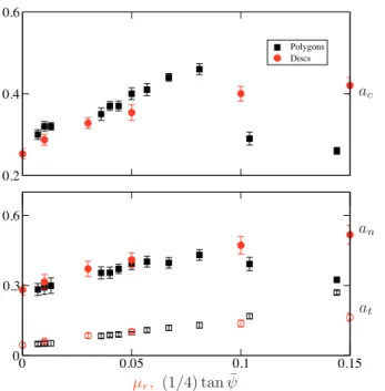
q/p ≃ (1/2)(ac+ an+ at), (4) where ac, an, and at, are the anisotropies of the angular distributions of contact orientations Pn(θ), normal forces
h fni(θ), and tangential forces h fti(θ), respectively, as a function of contact orientationθ, which are
approxi-FIGURE 4. Snapshots of the force network in (a) a system composed of disks with rolling friction (µr = 0.05) and (b)
a system composed of octagonal particles. The line thickness is proportional to the normal force. The floating particles are represented in light grey.
mated by their lowest order Fourier expansions:
Pn(θ) ≃ 1/π{1 + accos 2(θ−θc)},
h fni(θ) ≃ h fni{1 + ancos 2(θ−θn)},
h fti(θ) ≃ −h fniatsin(θ−θt), (5) whereh fni is the mean normal fore, and θc=θn=θt are the corresponding privileged directions, which, in the steady state, coincide with the principal stress direction. Equation 4 reveals distinct origins of the shear strength in terms of force and texture anisotropy. The empty symbols in Fig. 3 show q/p as predicted by Eq. 4. We see
that this equation approximates well the shear strength for all raw data.
The anisotropies ac, an, and at are shown in Fig. 5 as functions ofµr for the disks and of (1/4) tan ¯ψ for the polygons. It is remarkable that all anisotropies are almost identical between the two sets. This correspondence is only broken for polygons with small numbers of sides, i.e., for ns = 3 and 4. This happens because for these polygons the contact orientation is strongly influenced by the low rotational symmetry of the particles and the orientations of the sides rather than the relative positions of the particles.
As shown in [6], the mapping between rolling friction and angular shape of particles is also reflected by the probability density function (PDF) of normal forces.
0 0.3 0.6 0.2 0.4 0.6 Polygons Discs 0 0.05 0.1 0.15
FIGURE 5. Contact anisotropy ac (Up) and force anisotropies, an (full symbols) and at (empty symbols)
(Down), as functions ofµrfor the disks and of(1/4) tan ¯ψfor
the polygons. Error bars indicate the standard deviation.
CONCLUSION
To sum up, the simulations presented in this article pro-vide strong epro-vidence for the mapping between the two studied parameters, i.e., rolling resistance and shape an-gularity. This correspondence was established by con-sidering shear strength, solid fraction, force and fab-ric anisotropies, and the PDFs of normal forces in the steady state. A practical consequence of this finding is that rolling resistance may be employed to imitate the ef-fect of angular shape in discrete-element simulations of granular materials. More importantly, it suggests that the hindrance of particle rotations is a major effect of angular particle shape.
ACKNOWLEDGMENTS
This work was financially supported by the France-Colombia Ecos-Nord project.
REFERENCES
1. J. Ai, J.-F. Chen, J. M. Rotter, and J. Y. Ooi, Powder
Technology 206, 269–282 (2011).
2. K. Iwashita, and M. Oda, Journal of Engineering
Mechanics 124, 285–292 (1998).
3. J.-Y. Delenne, M. S. El Youssoufi, F. Cherblanc, and J.-C. Bénet, Int. J. Numer. Anal. Meth. Geomech. 28, 1577–1594 (2004).
4. F. Calvetti, and R. Nova, Powders and Grains Conference
Proceedings Vol. 1, 245–249 (2005).
5. M. J. Jiang, H. S. Yu, and D. Harris, Int. J. Numer. Anal.
Meth. Geomech. 30, 723–761 (2006).
6. N. Estrada, E. Azéma, F. Radjai, and A. Taboada, Phys.
Rev. E 84, 011306 (2011).
7. A. Taboada, K.-J. Chang, F. Radjai, and F. Bouchette, J.
Geophys. Res. 110, B09202 (2005).
8. J. J. Moreau, European Journal of Mechanics, A/Solids
13 (Suppl.), 93–114 (1994).
9. M. Jean, Mechanics of Geometrical Interfaces, Elsevier, New York, 1995, pp. 463–486.
10. M. Jean, Comput. Methods Appl. Mech. Engrg 117, 235 – 257 (1999).
11. F. Radjai, and V. Richefeu, Mechanics of Materials 41, 715 – 728 (2009).
12. N. Estrada, A. Taboada, and F. Radjaï, Phys. Rev. E 78, 021301 (2008).
13. G. Saussine, C. Cholet, P. Gautier, F. Dubois, C. Bohatier, and J. Moreau, Comput. Methods Appl. Mech. Eng. 195, 2841 – 2859 (2006).
14. F. Radjai, D. E. Wolf, M. Jean, and J.-J. Moreau, Phys.
Rev. Lett. 80, 61–64 (1998).
15. T. Matsushima, and R. Nova, Powders and Grains
Conference Proceedings Vol. 1, 1319–1323 (2005).
16. L. Rothenburg, and R. J. Bathurst, Geotechnique 39, 601–614 (1989).
17. F. Radjai, M. Jean, J.-J. Moreau, and S. Roux, Phys. Rev.