Astronaut-Centric Analysis of a Jetpack with
Integrated Control-Moment Gyroscopes for
Enhanced Extravehicular Activity Performance
by
Celena Dopart
B.S. Aerospace Engineering Worcester Polytechnic Institute, 2012Submitted to the Department of Aeronautics and Astronautics in partial fulfillment of the requirements for the degree of
Master of Science in Aeronautics and Astronautics at the
MASSACHUSETTS INSTITUTE OF TECHNOLOGY
June 2014
© Celena Dopart 2014. All rights reserved.
The author hereby grants to MIT and The Charles Stark Draper Laboratory, Inc. permission to reproduce and to distribute publicly paper and electronic copies of
this thesis document in whole or in part.
S
Author ...Si
Certified by..Si
Certified by.. Accepted by...ignature redacted
-- --- t ... ... .--- --- -DepA tment of Aeronautics and Astronautics
. k L-.M 2220M4
gnature redacted
Jeffrey A. Hoffman
Pofessor of the Practice of Aerospace Engineering
Thesis Supervisor
gnature redacted
' '
G--_~
Kimberly F. Jackson Member of the Technical Staff, Draper Laboratory
Thesis Supervisor Paulo C. Lozano MASSACHUSETUTE 1_-j75 OF TECHNOLOGY
JUN 16 2014
-IbRAR IES Cy ,/Signa~Ltre rete:d:
Astronaut-Centric Analysis of a Jetpack with
Integrated Control-Moment Gyroscopes for Enhanced
Extravehicular Activity Performance
by
Celena Dopart
Submitted to the Department of Aeronautics and Astronautics on May 22, 2014, in partial fulfillment of the
requirements for the degree of
Master of Science in Aeronautics and Astronautics
Abstract
As a stepping-stone towards eventual human exploration of Mars, NASA plans to explore low-gravity objects. Since the surface environments encountered on such missions would limit the independent mobility of astronauts, a maneuvering unit that offers counter reaction forces and torques during movements and tasks will likely be required. The next-generation maneuvering and stability system proposed in this research incorporates control moment gyroscopes (CMGs) into an extravehicular activity (EVA) jetpack device currently being considered at NASA Johnson Space Center (JSC). This Mobility Augmenting Jetpack with Integrated CMGs (MAJIC) system will offer rigid attitude control not previously required for EVA tasks.
This research project was designed to: (1) assess EVA task motions, astronaut dynamics, and mission concepts to support the objective comparison of the original jets-only Jetpack system and MAJIC, and (2) analyze the performance of both systems based on user evaluations of the two control configurations. An
EVA task list with associated motions and tools was compiled to develop a
relevant mission concept of operations that would inform the subsequent research objectives. A method for analyzing astronaut dynamics during these
EVA tasks was developed and used to compare system stability of the proposed
(CMG-augmented) vs. current (jets-only) control systems. The combined astronaut dynamics and controls models formed a full simulation that was integrated into a Virtual Reality (VR) environment at JSC to offer a platform for
two human evaluations comparing the proposed and current control systems.
Although computational analyses demonstrated increased attitude stability and decreased fuel consumption consistently across all missions and EVA tasks, results from the user evaluations were mixed. In the preliminary user evaluation, users showed overwhelming preference for MAJIC during worksite EVA tasks
that incorporated astronaut motions, but no trend for piloted missions that did not incorporate astronaut motions. The results of the follow-up user evaluation indicate that benefits of MAJIC are more pronounced in certain mission scenarios, including ones in which mass and moment of inertia properties are increased (e.g. when tools are used). Future work should explore these mission scenarios further and continue development of motion capture capabilities to include full-body actuation and contact models within the virtual reality environment.
Thesis Supervisor: Jeffrey A. Hoffman
Title: Professor of the Practice of Aerospace Engineering Thesis Supervisor: Kimberly F. Jackson
Acknowledgements
It has been my pleasure and privilege over the past two years to have many wonderful people in my life. To these individuals, I owe endless thanks for help and support during the completion of this thesis. You have all helped me maintain my sanity.
First and foremost, thank you to Jeff. Without your guidance and encouragement, I would not have had as fulfilling an experience here at MIT. Discovering my future advisor was a former astronaut made for an incredibly exciting start to this adventure. That excitement has remained with me over these two years and I am grateful to have had the opportunity to work with you. I learned so much and I thank you for your countless words of wisdom and envy-inducing stories - you have time and again reinforced my dream of becoming an astronaut.
To Kim, you are the reason that this thesis is complete-weeks early, no less-and that it is a comprehensive, coherent body of work. From answering the most menial questions (I know I need to make MATLAB do this, but ... how?) to helping
me stay relaxed and composed (the first day of a conference is supposed to be
dedicated to skiing, right?), you have kept me on track and in line throughout this
entire process. I am honored to be your first advisee, and hope any future ones work twice as hard and are half the trouble.
To the rest of my Draper advisors, supervisors, and colleagues, thank you not only for your technical and programmatic guidance, but also for making this experience unforgettable:
Michele, for training runs at altitude and hiking through a torrential downpour; Bobby, for your steadfast insistence that Word is superior to LaTeX; Kevin, for letting me hold the V2Suit's IMU hostage for weeks on end; Jared, because working on this project alone would have been an entirely different experience; and Todd, because I know the future of this work, whatever it may be, is in capable hands.
Thank you also to Draper itself, for the generous IR&D and UR&D funding. The support has provided me with extraordinary research opportunities, not to mention my rent, food, and beer - the only four things a grad student really needs.
To those at NASA Johnson Space Center's Virtual Reality Lab, thank you not only for your invaluable assistance setting up and running our evaluations, but also for introducing us to the best barbeque in town. To those at Draper Houston, thank you for being our line of communication with JSC, and for introducing us to the other best barbeque in town.
Outside of my MIT, Draper, and JSC research bubble, thank you:
To Houston friends, for filling my summer with Texas-style fun even though I thought I would melt whenever I stepped outside; DC friends, for making my visits home so perfect that going back to school was more difficult each time; and Boston friends, for reminding me that weekends do exist even as a grad student. To Harvard Stadium, Summit Avenue, and the numerous destination decks that kick-started my days, thank you for proving three times a week that with the right perspective and enough hugs anything after 7:30 AM is a breeze.
To my family, who have believed in me turning my childhood fantasies into reality, thank you for absolutely everything you are to me and everything you do. Specifically:
Alethea, for the years of sisterly 'wisdom' you bestowed (inflicted?) upon me. I am tough because of you and still think you are the coolest older sister a girl could have. Dad, for making the decision to come to MIT a given even when it was hard, and for the Star Wars marathons that undoubtedly fueled my obsession with space. Mom, for being the best example of a strong, independent woman a daughter could hope for, and for making me spanakopita every single time I come home.
To all the other people and places that made my time in Cambridge a little more
joyous:
Bikram Boston and Prana Power studios, for relieving my stress and helping me find balance; Life Alive, for the mouth-watering Mystic Mountain; Alfonso Cuar6n, for Gravity's perfectly timed PR campaign for jetpacks; Swissbakers, for quiche, bacon, and coffee; and my bicycle, for saving me hours upon hours of commute time.
And finally, thanks to you, dear reader. If you are not mentioned above, I hope you have found your way here because this work has changed the future of
Table of Contents
Abstract ... 3
Acknow ledgem ents... 5
Table of Contents... 7
List of Figures ... 11
List of Tables...13
A cronym s...15
1. Introduction and Background ... 17
1.1 EVA M obility Near Low-Gravity Environm ents ... 18
1.2 M aneuvering Units... 20
1.3 Thesis Overview ... 22
2. Astronaut D ynam ics M odel... 23
2.1 Astronaut Body M odel ... 23
2 .1 .1 G E B O D ... 2 3 2.1.2 EM U and Jetpack M ass Properties Augm entation... 25
2.2 Astronaut Dynam ics M odel... 28 2 .2 .1 D ev elo p m en t... 2 8
2.2.2 Exam ple A nalysis ... 31
2.3 EVA A ssessm ent... 33
2.3.1 M otion ... 33
2.4 Sum m ary... 38
3. M ission A nalysis... 39
3.1 Concept of O perations ... 40
3.1.1 M ission Selection ... 40
3.1.2 M ission Building Blocks... 41
3.2 Block A nalysis ... 42
3.3 M ission A nalysis for CM G Sizing... 48
3.4 Sum m ary... 53
4. Prelim inary U ser Evaluation... 54
4.1 V irtual Reality G raphics Environm ent... 55
4.2 Evaluation D esign ... 56
4.2.1 Part 1 (O bstacle Course) D escription ... 56
4.2.2 Part 2 (Sim ulation Video) D escription... 58
4.2.3 Part 3 (Operational Functions and Interface) Description... 59
4.3 Evaluation Results... 60
4.3.1 Part 1 (O bstacle Course) Results... 60
4.3.2 Part 2 (V ideo Sim ulation) Results ... 62
4.3.3 Part 3 (O perational Functions and Interface) Results ... 63
4.3.4 Evaluation Conclusions...66
4.4 Sum m ary... 66
5. Follow -up U ser Evaluation ... 67
5.1 Real-tim e M otion Capture ... 67
5.1.1 Sensor Selection and Integration ... 68
5.1.2 Real-tim e Integration ... 73
5.2.2 Part 2 (ISS EVA) Description ... 79
5 .3 E v alu ation R esu lts...8 2 5.3.1 Part 1 (Obstacle Course) Results... 82
5.3.2 Part 2 (ISS EVA) Results... 85
5.3.3 Hum an Interface and Application Feedback ... 89
5.3.4 Evaluation Conclusions... 90
5 .4 S u m m ary ... 9 1 6. Sum m ary and Conclusions ... 92
6 .1 T h esis R ev iew ... 9 2 6.2 Limitations and Future W ork... 94
Appendix A: Prelim inary Evaluation Questionnaires... 97
Appendix B: Follow-Up Evaluation Questionnaires ... 103
Appendix C: ANOVA Tables ... 107
List of Figures
2.1 Body M odels... 25
2.2 Overall System Center of Mass Location... 27
2.3 Astronaut Body M odel... 29
2.4 Sim ple M otion... 32
2.5 Simple Motion Torque Profile... 33
2.6 H am m er... 36
2.7 EVA Pow er Tool... 36
2.8 Smart Power Tool ... 36
3.1 Process of Developing Missions from Building Blocks ... 41
3.2 Jets-Only and CMG Attitude Errors for Mission Building Blocks ... .43
3.3 Asteroid Sampling Mission Trajectory ... 50
3.4 Incapacitated Crewmember Rescue Grasp... 51
4.1 EDGE-Rendered Astronaut and Jetpack on Itokawa Surface ... 55
4.2 User's Initial View of the Asteroid Obstacle Course... 57
4.3 User Preference of Control Config. from the Obstacle Course Runs.. 60
4.4 Box Plot of Fuel Consumption for Obstacle Course Run ... 62
4.5 User Preference of Control Config. from ISS EVA Videos ... 62
4.6 Average User Rating of Five Potential Operational Functions ... .64
5.1 Forearm Unit Comparison ... 70
5.3 Simulink Block Incorporating Real-Time Motion Capture into the
Astronaut Dynamics Model ... 74
5.4 Attitude Error Over Time ... 76
5.5 Maximum Attitude Error vs. Astronaut Size... 76
5.6 Heads-Up Display with Improvements Indicated ... 79
5.7 User with VR Helmet, Chest Plate, and VN-100 IMU on Right A rm band ... 80
5.8 User Preference of Control Config. from the Obstacle Course Runs.. 83
5.9 Box Plot for Fuel Consumption ... 84
5.10 User Preference of Control Config. from the Motion Capture Runs ... 86
5.11 Box Plot of Max. Attitude Error ... 87
5.12 Box Plot of Max Attitude Error for ISS EVA Runs... 88
List of Tables
2.1 M odel Astronaut Size... 24
2.2 EMU and Jetpack Assembly Mass Breakdown ... 26
2.3 Whole System Mass Breakdown ... 27
2.4 Tool Specifications and Descriptions ... 35
2.5 EVA Task Descriptions ... 37
3.1 Task Profiles... 46
3.2 Fuel Consumption ... 48
3.3 Monte Carlo Results ... 52
4.1 Operational Functions ... 59
5.1 Range of Astronaut M asses ... 75
5.2 Maximum Attitude Error ... 86
C.1 Obstacle Course Fuel Consumption ANOVA Results... 107
C.2 ISS EVA Attitude Error Without Tool ANOVA Results ... 107
C.3 ISS EVA Attitude Error With Tool ANOVA Results ... 107
C.4 ISS EVA Fuel Consumption Without Tool ANOVA Results ... 108
Acronyms
AMRV = Astronaut Maneuvering Research Vehicle
AMU = Astronaut Maneuvering Unit
ANOVA = Analysis of Variance ATB = Articulated Total Body
CMG = Control-Moment Gyroscope
COM = Center of Mass
D-RATS = Desert Research and Technology Studies
DOF = Degree of Freedom
DOUG = Dynamic On-Board Ubiquitous Graphics
EDGE = Engineering DOUG Graphics for Exploration
EMU = Extravehicular Mobility Unit EVA = Extravehicular Activity GEBOD = Generator of Body Data
HITL = Human-in-the-Loop
HUD = Heads-up Display
HUT Hard Upper Torso
IMU = Inertial Measurement Unit
ISS = International Space Station JSC = Johnson Space Center
LCVG = Liquid Cooling and Ventilation Garment
LTA = Lower Torso Assembly
MAJIC = Mobility Augmenting Jetpack with Integrated CMGs
MMSEV = Multi-Mission Space Exploration Vehicle
MMU = Manned Maneuvering Unit MOI = Moment of Inertia
NASA = National Aeronautics and Space Administration
NEA = Near-Earth Asteroid
NEEMO = NASA Extreme Environment Mission Operations PLSS = Primary Life Support System
SAFER = Simplified Aid for EVA Rescue
SSA = Space Suit Assembly
Chapter
1
Introduction and Background
While the immediate future of human space exploration is undecided, NASA intends to eventually send humans to Mars. As a stepping-stone towards this goal, a number of potential missions to explore zero- or low-gravity environments have been proposed or discussed, including asteroids and Martian moons. To maximize performance of astronauts during extravehicular activity
(EVA) in these unfamiliar environments, an advanced maneuvering unit will
likely be required. Previous EVA tasks that made use of an independent maneuvering unit consisted primarily of satellite capture, satellite repair, and rescue maneuvers. In these new non-ISS and non-Space Shuttle environments, however, astronauts will likely be performing tasks that require precise motor control, such as sample collection and equipment deployment. A jets-only mobility system would have to fire thrusters to counteract the changes in center-of-mass (COM) and moments of inertia (MOI) that result from astronaut
movement, negatively affecting task performance. This research proposes
incorporating control-moment gyroscopes (CMGs) into a jets-only mobility device currently being considered at NASA Johnson Space Center (JSC).
CMGs are constant-speed rotors with a gimbal that changes the direction of the rotor's angular momentum vector. A single CMG provides one attitude degree of freedom (DOF) and the most common configurations, including the
pyramid array in this research, consist of at least four CMGs. These momentum-exchange devices are electrically powered and thus consume no fuel. Additionally, CMGs provide a continuous range of motion where jets are limited
by the minimum thruster valve on-off time. The Mobility Augmenting Jetpack
with Integrated CMGs (MAJIC) proposed in this research will conserve fuel and offer the rigid attitude control that is necessary for these new missions but not provided by any past or current maneuvering unit.
1.1 EVA Mobility Near Low-Gravity Objects
NASA has long had goals to send humans to Mars, with recent plans
projecting achievement within the next three decades. A number of stepping stones towards this eventual human Mars exploration have been discussed, including crewed asteroid missions, return to the moon, and exploration of Martian moons [1-2]. These missions are argued to be more realistic in the short-term since they could happen sooner than a manned landing on Mars, cheaper as a result of less required delta-v, and safer than a Mars landing [3]. Additionally, these missions do not merely offer programmatic and operational benefits of human venture beyond Earth orbit; they have the potential for more practical applications as well, such as extraction and utilization of resources and planetary defense and asteroid impact mitigation [4]. The scientific potential is also compelling in terms of better understanding the solar system.
In many of these environments, the gravity is too weak to allow astronauts to walk on the surface. Instead, they will require some form of mobility technology -one that is robust and flexible in order to benefit both current missions and any of these future missions that might reach fruition. Several different EVA technologies have been developed and studied to aid in this objective, including translation lines, EVA booms, and rope tethers [4-9].
A translation line device allows setup and use of several translation lines on a
surface-EVA booms are modeled after the robotic arm's boom on the ISS and can serve as
a robotically controlled translation aid when one end is attached to NASA's Multi-Mission Space Exploration Vehicle (MMSEV) or a similar EVA exploration platform and the other is attached to the astronaut. A boom can also be attached to two translation lines or anchored surface mounts to allow a restraint for performing tasks along the length of the boom. Finally, the boom can be "walked" along the surface by an EVA crewmember by releasing one end and using it as a restraint [5]. A drawback for these two methods of surface translation and
stabilization is that both require local anchoring. Techniques do exist to anchor the boom, the translation line's central hub, or even the astronaut to the surface. These include driving in pitons, firing penetrators that resist extraction, screwing in large area augers, welding tie-downs into metal, ice, or silicate rock, using fluked anchors, and burrowing completely into the regolith [6]. In some cases, for example if an asteroid is metal-rich and magnetized, a magnetic anchor could be used [7]. However, the success of all these anchoring methods depends heavily on the composition and characteristics of the destination surface [8].
A pair of MIT researchers have offered a method for EVA surface exploration
that eliminates the problem of surface composition [9]. The method "lassoes" two ropes around the circumference of an asteroid and harnesses an astronaut between them. The harness contraption enables the astronaut to slide along the
two ropes, acting as tethers that offer stabilization and the freedom to move about the entire circumference. However, movement will be constrained to the corridor between the two ropes, significantly limiting the scope of exploration. Further, this method is limited to small bodies like asteroids, and is not feasible for Martian moon missions.
What all these methods also have in common is the necessity for some level of setup, whether by anchoring central hubs or by looping ropes around an asteroid before the main EVA objectives can be achieved. This drawback, in addition to the
other disadvantages previously mentioned, underlies the motivation for the current research. A manned maneuvering unit offers full range of exploration of the destination surface, does not depend on the composition or character of the
surface, provides a method for translating to and from a home-base spacecraft, and eliminates the need for initial setup to begin EVA tasks.
1.2 Maneuvering Units
Over the years, a number of maneuvering units have been developed, tested, and used. The first personal propulsion unit that NASA astronauts used in space was a hand-held compressed air gun unit that proved troublesome in testing in
1963. Its cumbersome handling qualities and quick fuel depletion resulted in the
unit never gaining popularity for EVA use [10]. Even while the hand-held unit was being developed and tested, research was progressing on backpack-like systems for advanced mobility during EVA. The first of these jetpack systems was developed by the US Air Force in the 1960s, and completed in April 1966. Called the Astronaut Maneuvering Unit (AMU), it had self-contained life support, telemetry, communications, propulsion, and stabilization systems [11]. The first unit flew on Gemini 9 in June of 1966 and was to be tested on a spacewalk by pilot Gene Cernan [10]. Unfortunately, due to safety concerns during the EVA, the system was never tested.
Another personal maneuvering unit test bed, the Astronaut Maneuvering Research Vehicle (AMRV), was analyzed aboard Skylab in the M509 experiments [12]. Like the proposed MAJIC system, the AMRV incorporated CMGs into its design. The purpose of the M509 experiments was to evaluate the utility of
several astronaut maneuvering techniques to further establish design
requirements for future maneuvering units [13]. The AMRV eventually developed into the Manned Maneuvering Unit (MMU), but the evolved design abandoned the inclusion of CMGs. This was due in part to limits of CMG technology and also because simply providing effective mobility capabilities was a priority over rigid stabilization for EVA missions at the time.
The MMU, evolved from the AMRV, was designed at NASA JSC. This self-contained propulsive backpack unit was used several times during the Space
completed without the MMU by using the robotic arm, translating with handholds, using tethers and restraints, or leveraging the maneuverability of the space shuttle itself. Additionally, the 1986 Challenger accident prompted new safety rules that would require expensive changes to the existing MMU [10].
The MMU was succeeded by a smaller, simplified version called the Simplified Aid for EVA Rescue (SAFER). SAFER was designed for emergency self-rescue in cases where an astronaut becomes detached from a safety tether and no vehicle can provide rescue capability. SAFER is worn by every International Space Station (ISS) crewmember using the Extravehicular Mobility Unit (EMU), one of the current spacesuits used on the ISS. However, as the name suggests, SAFER is for emergency use only and is not intended to provide primary EVA mobility.
NASA JSC is considering the development of a Jetpack device that will
evolve the SAFER concept from a contingency unit into an primary maneuvering unit by leveraging the existing avionics system, redesigning the mechanical and propulsive systems, and adding hands-free functionality [14]. This concept will reintroduce the capabilities of the MMU and will certainly have applications for low-gravity missions; however, maintaining rigid attitude control to provide a stable work platform has not been a primary design requirement thus far. Jetpack's 24 cold-gas thrusters that respond to translation and attitude commands will need to constantly fire to compensate for changes in inertia, center-of-mass location, and induced torques, resulting in motions that could interfere with tasks requiring fine motor control.
Consequently, this research pursues the use of CMGs where the MMU did not and incorporates these attitude control devices into the Jetpack. The objective is to offer greater attitude stability to EVA astronauts during all stages of an EVA in a weightless environment while conserving fuel.
1.3 Thesis Overview
This thesis investigates potential improvements offered by a CMG-augmented mobility unit in the context of current and future EVA missions. Two objectives are specifically addressed:
Objective 1: Assess EVA task motions, astronaut dynamics, and mission concepts
to support the objective comparison of JSC's jets-only Jetpack system and MAJIC
Objective 2: Analyze the performance of both systems based on user evaluations
of the two control configurations
This thesis addresses these objectives in six chapters. Chapter 2 discusses the development of an astronaut dynamics model used throughout the thesis as a means for analysis and additionally describes an investigation of EVA tasks, tools, and methods. This investigation is used to inform the concept of operations for MAJIC developed in Chapter 3. This concept of operations provides reference mission scenarios that are analyzed for fuel consumption and attitude stability
by integrating the astronaut dynamics model with a simulation of the jetpack
control system. Chapters 4 and 5 outline preliminary and follow-up user evaluations, respectively, and present trade-offs between jets-only and MAJIC system designs based on simulation data and user feedback. Chapter 6
summarizes the research, discusses the limitations, and presents
Chapter 2
Astronaut Dynamics Model
An astronaut dynamics model was developed to simulate EVA tasks of interest and calculate whole-body center of mass, moment of inertia, and torque profiles. These three outputs were integrated into a larger comprehensive system simulation environment that includes CMG and jet control algorithms. The two primary inputs into the astronaut dynamics model are human body parameters and basic motions, both of which are defined based on a simple astronaut body model. The development of these inputs, the astronaut body model, and the astronaut dynamics calculations are detailed in this chapter.
2.1 Astronaut Body Model 2.1.1 GEBOD
The unsuited astronaut body parameters were computed using the
GEBOD (Generator of Body Data) program [15]. The program, developed at
Wright-Patterson Air Force Base, calculates body segments' geometric and mass properties based on subject's gender, height, and weight, specified either by percentile or user-input values. The tool uses regression equations and is based
on an Articulated Total Body (ATB) 17-segment human model. Regression
equations are a widely used method in anthropometry for predicting unknown body dimensions from known ones, and use an existing database of measurements taken from human subjects. GEBOD utilizes four groups of
regression equations to determine the body dimension set, joint location coordinates, segment volumes, and principal moments of inertia. Each group of equations includes two sets that this research utilizes: male adult subjects and female adult subjects. For a more in-depth description of the program's calculations, see [15].
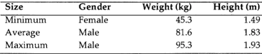
With GEBOD, the astronaut dynamics model can be modified for analysis of any size astronaut. Three astronaut sizes, summarized in Table 2.1, were chosen for this research's main analysis to encompass the range of sizes possible with NASA's current size restrictions: a minimum size female astronaut, an 'average' astronaut, and a maximum size male astronaut. The minimum size astronaut uses NASA's minimum height restriction of 1.49 m (58.5 in) and GEBOD's 5th-percentile female weight of 45.3 kg (99.9 lbs). The 'average' astronaut is modeled after the astronaut size currently used at Johnson Space Center for mechanical development of the Jetpack, which is an 81.6 kg (180 lbs),
1.83 m (72 in) male. The maximum size astronaut uses NASA's maximum height
restriction of 1.93 m (76 in) and GEBOD's 95th-percentile male weight of 95.3 kg (210 lbs). These parameters are used with GEBOD to compute mass properties for the 14 segments of the simple astronaut body model used for this research. While the majority of the analyses in this document are based on these three astronaut body sizes, the methods developed with this research can be reanalyzed using any sizing specifications desired. Section 5 discusses simulation sensitivity to astronaut sizing.
Table 2.1: Model Astronaut Sizes
Size Gender Weight (kg) Height (m)
Minimum Female 45.3 1.49
Average Male 81.6 1.83
Maximum Male 95.3 1.93
the Extravehicular Mobility Unit (EMU), the pressurized space suit astronauts wear during EVA. As shown in Fig. 2.1, GEBOD's 2, 3, 4, and 5 segments are combined into one main "torso" segment (L2) in the astronaut body model. The combination of these segments accounts for the rigidity of the torso, neck, and head of the EMU and restricts the independent mobility of the four segments. The two body models, with their respective numbering schemes, are illustrated in Figures 2.1a and 2.1b.
3b L- '
a(A
(a) GEBOD Human Body Model (b) Astronaut Body Model
Figure 2.1: Body Models
2.1.2 EMU and Jetpack Mass Properties Augmentation
Anytime astronauts venture outside their vehicle for an EVA, they wear a pressurized space suit to protect their bodies from the harsh environment. The suit used for Shuttle operations and current International Space Station operations is the Extravehicular Mobility Unit (EMU), which provides environmental protection, mobility, life support, and communication for crewmembers during EVA. It is an integrated assembly comprised of two major subsystems, the Life Support Subsystem (LSS) and the Space Suit Assembly
(SSA), as well as other accompanying support and supplementary gear [16].
The two subsystems can be divided into seven main components. The Liquid Cooling and Ventilation Garment (LCVG) consists of liquid cooling tubes
flow to the LSS. The Hard Upper Torso (HUT) provides the structural mounting interface for most of the EMU (helmet, arms, lower torso, Primary Life Support System (PLSS), display and control module, and electrical harness). The Arm Assembly includes the shoulder and elbow joints, as well as the wrist connection to the Gloves, which are relatively self-explanatory. The Lower Torso Assembly (LTA) contains the brief/waist assembly, legs, and boots, each comprised of flexible sections to allow for joint mobility. The Helmet is made of a clear polycarbonate bubble, neck connection, and ventilation pad. Currently, the EMU also includes a SAFER attachment that provides emergency mobility in the event of separation from the vehicle or station. For this research, the SAFER assembly is replaced with JSC's Jetpack assembly, which includes the Jetpack mobility unit as well as the PLSS. The masses of these assemblies are listed in Table 2.2 [16-17].
Table 2.2: EMU and Jetpack Assembly Mass Breakdown
Part Mass (kg)
Liquid Cooling and Ventilation Garment (LCVG) 2.94
Hard Upper Torso (HUT) 12.29
Arm Assembly 7.87
Gloves 2.31
Lower Torso Assembly (LTA) 20.72
Helmet 8.23
Jetpack Assembly (including PLSS) 119.3
The unsuited astronaut body model discussed in the previous subsection is augmented with the mass properties of the EMU and the Jetpack Assembly. The part masses from Table 2.2 are added to their associated segment mass, shown in Table 2.3, and segment inertias are increased proportionately with mass increase. The center of mass locations are assumed unchanged for all segments except the torso, which is adjusted to incorporate the added mass and
dimensions of the Jetpack Assembly. This is done based on the known
dimensions of the JSC model astronaut, the overall system center of mass (Fig. 2.2), and the calculated center of mass of an unsuited JSC model astronaut.
body positions. The adjusted whole-body center of mass location is in the torso; that segment's center of mass is shifted higher up and slightly back by the selected multipliers in order to account for the Jetpack's mass properties.
Figure 2.2: Overall system (JSC astronaut, EMU, Jetpack Assembly) center of mass location
Table 2.3: Whole System Mass Breakdown gment Description
Upper Torso/ Central Torso/ Head/ Neck Pelvis
Upper Arm
Associated Parts Helmet, HUT, Jetpack
Assembly, LCVG LTA, LCVG
Arm Assembly, LCVG
2 Lower Arm Arm Assembly, LCVG
2 Hand Glove
Upper Arm Arm Assembly, LCVG
2 Lower Arm Arm Assembly, LCVG
2 Hand Glove Thigh Calf Foot Thigh Calf Foot Combined Mass (kg) 174.31 17.51 4.33 3.04 1.67 4.33 3.04 1.67 15.17 6.02 1.49 15.17 6.02 1.49 255.27 LTA LTA LTA LTA LTA LTA Total Mass Se 2 1 3a 4a 5a 3b 4b 5b 7a 8a 9a 7b 8b 9b
2.2 Astronaut Dynamics Model
The primary purpose of the astronaut dynamics model is to compute the center of mass, moment of inertia, and torque profiles associated with a given astronaut body model and prescribed motion. These outputs are used in the overall system simulation in order to calculate the required control actuation to maintain stability during various motions.
2.2.1 Development
The code for the astronaut dynamics model is adapted from a previously designed model created to simulate astronaut self-rotation [18]. The 37 degree-of-freedom (DOF) astronaut body model is defined in the code as 14 chain-linked segments as shown in Figure 2.3a, with the pelvis (segment Li) as the base. Each segment consists of a point mass at the segment's center of mass with a corresponding moment of inertia. Segment reference frames are defined at the base joint of the corresponding segment; for example, the reference frame for the pelvis, segment L1, has its origin at the base of the pelvis, joint 1. This pelvis reference frame, or the 1-frame, is the frame from which whole-body properties are defined. Every other link is a 'child' link to the pelvis 'parent', and this pattern continues outwards to the feet and hands, which have no corresponding 'child' links of their own.
Figure 2.3b shows the astronaut body model side view depicting the location of the Jetpack frame of reference (Point J). Point J is the origin of the
J-frame, which is coincident with the entire system center of mass in the neutral position where the legs are straight down and the arms are straight down by the sides.
(a) Front view
Figure 2.3: a) Astronaut Body Model
Any motion is defined by joint position, velocity, and acceleration. The kinematic modeling of the motions in this code is based on quaternion representation of rotation, rather than the Euler angle representation. A quaternion's four quantities enable singularity-free mathematical representation of orientations, and are thus preferable to the three-quantity Euler angle method.
A quaternion, q, has one real part and three imaginary parts, written as
q =q + q2i+ q3j+ q4k (2.1)
An orientation can be represented as a quaternion rotation,
qrot = [cos(8/2) sin(6/2) e]T = , (2.2)
where & is the angle of rotation about the axis e described by e = [e1 e2 e3]T.
I L
X
z
s2
X14z
(b) Side view 5b 46 7b 70m ? Ob 8The angular velocities ((o, wy, Wz) and angular accelerations (as, ay, az)
can be calculated using the quaternion derivatives through the matrix equations
W =
[y
= 2QT4 (2.3 [a=-ay where = 2QT(4
-q3 -q4 q1 q2 -q2 q, q4 -q3 - Qo) -q1 q3 -q2 q1 (2.4) (2.5)To map motions from one segment to the next in the linked astronaut body model, a transformation consisting of a rotation matrix based on each segment's orientation and a translation based on its lengths is used. Based on each joint's quaternion orientation written as qrot, the rotation matrix from the previous link to the current joint's link is:
2qJ + 2q2 - 1 R = 2q 2q3 - 2q1q4 .2q2q4- 2q1q3 2q2q3 + 2q1q4 2q, + 2q3 _ 1 2q3q4 - 2q1q2 2q2q4 + 2q1q3 2q3q4 + 2q1q2 2q, + 2q4 - 1
Linear velocities can then be calculated by a forward propagation from link 1 to link N, VLi = I RJ (VLj jEPi (2.7) (2.6) ) + OLj X Li-
,
The summation is performed over the set of parent links, Pi, for the given link, and Lis the distance from frame i to frame j. Linear accelerations can then easily be found by differentiating. In this research, the astronaut's body is fixed with respect to the inertial frame. In other words, to an outside observer, the astronaut does not rotate or translate as a result of the movement. This simulates the function of the control algorithm, providing stability to astronauts while they work in zero- or microgravity environments. Thus, the base link (pelvis, Li) has zero angular and linear velocity and acceleration, and equation 2.5 can be fully solved.
The joint torques, t, are then found using the backwards recursion from the original code [18]:
Ti = Rj +r*, i = N,...,1, (2.8)
jEc1
where r1 maps the torques of the child joints, C, to the current joint i, and T* is
the torque due to coupling forces applied to link i by link i - 1 and i + 1 and the rotation of the reference frame. External torques and forces can be included in this calculation by applying a torque or force to a designated joint. This functionality is utilized in the next subsection by applying torques and forces to the hand segments to simulate tool use.
Using Eq. 2.8, the net torque about the J-frame origin required to maintain the fixed inertial position is computed, and the center-of-mass location and moments of inertia are calculated as well as the body position changes. These three outputs are computed with respect to the J-frame.
2.2.2 Example Analysis
The following section offers an analysis of a simple motion trajectory to demonstrate the astronaut dynamics model. In this simple case, there are no external forces or external torques. In this motion, both arms swing upward from the neutral straight down position to directly outward from the chest, and the
speed of the motion is varied to demonstrate the resulting changes in the torque profile. Figure 2.4 depicts the initial and final body positions for the defined motion. The star represents the whole-body center of mass, and the transition from 2.4(a) to 2.4(b) reflects the change due to the altered arm position.
4$ 5 - .
1 1 0 5
1 4$ 4
(a) Initial position (b) Final position
Figure 2.4: Simple motion
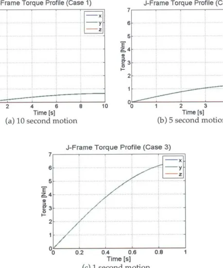
Three simple cases are run using the described motion. The three cases differ only in the length of time to complete the motion: the slowest at 10 seconds for case one (Figure 2.5a), 5 seconds for case two (Figure 2.5b), and the fastest at 1 second for case three (Figure 2.5c).
As is expected from the defined motion, the required torque is entirely about the J-frame y-axis. In other words, if the astronaut were unrestrained, raising the arms would cause the astronaut to tilt forward. Additionally, the maximum torque increases as the speed of the arms increases, from 0.64 Nm for a 10 second motion to 6.43 Nm for a 1 second motion. The torque profiles shown in Fig. 2.5 are the astronaut dynamics input to the CMG-augmented Jetpack system simulation.
-Frame Torque Profile (Case 1) 7 6 5 X 4 2'3 0 2-7 6 5 T Cr3 0 2 1
J-Frame Torque Profile (Case 2)
-- x - - -y--z .... .. .....-.. -. -. ... .. -- ...-. ... 8 10 "0 1 2 3 4 5 Time [s] (b) 5 second motion 7 6 5 -4 3 0 2 I
J-Frame Torque Profile (Case 3)
-- x. - -y.. .. -- ---.. ... ... ... .... ...-0.2 O4 06A Time [s] (c) 1 second motion 0.8 1
Figure 2.5: Simple motion torque profiles
2.3 EVA Assessment 2.3.1 Motion
Because one of the main inputs to the astronaut dynamics model is motion, a preliminary astronaut task list has been compiled to include various tasks that might be enacted during an asteroid EVA. The task list provides necessary inputs for the astronaut dynamics model, including external forces and torques, mass properties of any corresponding tools, and definition of the motion trajectory. The task list is organized by grouping similar tasks and motions
J -x -- z -. ... . -..-. . .-.. -.. ... ... ... .. ... -- --- .... .... .... - ... . .. ... ... -2 4 6 Time [s] (a) 10 second motion
together, and is expected to ultimately help pinpoint Jetpack control modes based on intended task type.
Limited information is available concerning tool specifications,
corresponding motions, and external force and torque data; however, guidelines described here will be used to continue populating a generalized task list and offer minimum and maximum torque limits for each task. The maximum external torque to which a crewmember can comfortably react while in free float is just under 70 N-m (50 ft-lb), and the maximum external force is just under 220
N (50 lbf) [19]. Impulses for each can be higher, but generally astronauts are
instructed to avoid exceeding the limits. In terms of motion characteristics, arm movements will likely be the most common, given the type of motions seen on
EVA (repairs, geological sampling, equipment deployment). Most arm motions
remain within the immediate work envelope of the astronaut's chest, defined as roughly between the shoulders, between the eyes and navel, and within the forward reach of the arms with a slight bend.
Since near-Earth asteroid (NEA) exploration is one of the EVA areas that would likely benefit from a CMG-stabilized Jetpack system, an initial task assessment was based on prior NEA mission analysis programs, namely the
NASA Extreme Environment Mission Operations (NEEMO) and Desert Research
and Technology Studies (Desert RATS, or D-RATS). Missions from both programs included analyses of task procedures and tool use, and given the science goals of NEA exploration, these primarily consisted of geological sampling methods [4]. Between the two programs, three categories of sampling techniques were tested: surface sampling, soil sampling, and depth sampling [4]. Surface sampling consists of hand, bag, or contact surface pad collection, soil sampling consists of clamshell device or scoop collection, and depth sampling consists of core tube or drive tube collection [20]. The three categories have generally increasing levels of reaction forces. Surface sampling-picking up a rock, for example-tends to have the lowest reaction force, while depth
require a hammer to separate it from a larger rock, which creates a significantly higher impulse.
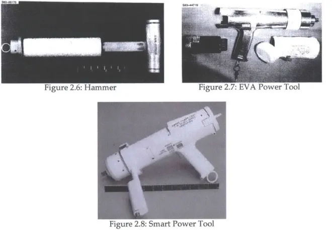
While specifications for the aforementioned sampling tools are not readily available, several tools from the EVA Tools and Equipment Reference Book have been chosen as representative EVA tools for this research. An EVA Hammer, an
EVA Power Tool, and a second "Smart" Power Tool have been selected to offer a
range of external impulses, forces, and torques. Selected tool specifications and descriptions are included in Table 2.4 and shown in Figures 2.6-8 [21].
Table 2.4: Tool Specifications and Descriptions
Tool Mass (kg) Length (cm) Description
Hammer 0.91 27.94 Tool used for disconnect and jam
removal with fiberglass shaft and brass head to damp the shock of hammer blows. EVA Power Tool Smart Power Tool 1.33 5.44
29.85 Battery-powered, two-speed / four-torque unit with forward! reverse switch. Used for any EVA task that requires a portable torque device.
36.83 Hand-held, battery-powered,
microprocessor-controlled device with regulated torque and revolution.
Parameters are keyed in by the user and electronically regulated by the tool.
-u
NI'WV-igure L.o: riammer
Figure 2.8: Smart Vower 1001
A task list compiled from these tool specifications, the minimum and
maximum guidelines described in the beginning of this section, and the task procedures learned from NEEMO and D-RATS missions offer a concise resource from which motion inputs for the astronaut dynamics model were easily compiled. The task list mentioned earlier, organized by task type, is given in Table 2.5. It includes the task, description of the motion, and the maximum resulting torque from the standalone astronaut dynamics model (using a maximum sized 210-lb, 76-in astronaut). For each task in Table 2.5 involving a tool, the mass properties of the tool were incorporated into the hand segment. These motions were then be combined into various motion profiles and integrated into the system simulation environment for analysis.
Table 2.5: EVA Task Descriptions
Magnitude
Task Description of Maximum
Torque (Nm)
Category I: Using Tools
Hammer The bent right arm swings down to the front, 59.54 impacts with a 10ON impulse to correspond with a
hammer strike, and swings the arm back to the starting position. Modeled with hammer in hand.
Min Torque Bent right arm holds the power tool within the work 20.30 Power Tool envelope in a stationary configuration with the
power tool powered up to its minimum torque (20.3
Nm).
Max Torque Bent right arm holds the power tool within the work 135.60 Power Tool envelope in a stationary configuration with the
power tool powered up to its maximum torque (135.6 Nm).
Category II: Reaching for or Passing Tools
Hand to Hip Bent arm swings downward from work envelope to Reach slightly back past the left hip and returns.
8.87
Hand to Hip Reach With Tool
Hand to Side Reach
Hand to Side Reach With Tool
Overhead Reach Overhead Reach With Tool Overhead Two-Arm Reach Overhead Two-Arm Reach With Tool
Same as "Hand to Hip Reach," but modeled with a heavy tool in hand. Tool used is the Smart Power Tool.
Straight right arm swings horizontally from out to the side to straight forward, then returns.
Same as "Hand to Side Reach," but modeled with a heavy tool in hand. Tool used is Smart Power Tool.
Bent right arm swings from work envelope up to over the head and returns.
Same as "Overhead Reach," but modeled with a heavy tool in hand. Tool used is Smart Power Tool.
Both bent arms swing from work envelope up to over the head and return.
Same as "Overhead Two-Arm Reach", but modeled with a heavy tool in both hands. Tool used is Smart Power Tool.
Category III: Miscellaneous
Hip Flexion Both legs swing from straight down to straight out 154.33 in front, and back.
29.66 16.58 39.87 9.21 32.76 18.42 49.88
2.4 Summary
The astronaut dynamics model discussed in this chapter provides the foundation for the analyses comparing JSC's Jetpack design to the MAJIC design that follow in the remainder of this thesis. The EVA task and tool investigation provides a framework for mission scenario development that supports these analyses. Developing the capability to compare the two systems based on astronaut EVA motion disturbances and not only on mission trajectory and navigation adds a level of focus to the analysis. This astronaut dynamics model offers a more detailed and comprehensive comparison of system performance in the context of actual EVA tasks.
Chapter 3
Mission Analysis
The astronaut dynamics model developed in Chapter 2 is used in conjunction with a control model developed using MATLAB/Simulink [22]. The control model calculates the jet and CMG commands based on the astronaut dynamics model torque, moment of inertia, and center of mass profiles, as well as mission specifications such as trajectory, velocity, and control mode [22]. For a more detailed description of the control model, please see [23]. This system simulation allows for a comprehensive analysis of astronaut motions during a wide range of mission scenarios and trajectories. Missions are defined by an astronaut motion profile, a mission trajectory and timeline, and the specified control mode. In this chapter, a number of mission scenarios are analyzed using the comprehensive model to compare attitude error and fuel consumption between the original jets-only attitude control system, and the proposed CMG-augmented MAJIC control system. Additionally, two approaches are presented to generate and analyze sample missions, which will be utilized in a Monte Carlo simulation to determine optimal size for the CMGs.
To guide these analyses, a concept of operations for MAJIC is presented, which includes several scenarios that would benefit from the system's stiffer work platform and reduced fuel consumption. These scenarios span a range of work environments and tasks, including asteroid or Martian moon surface sample collection, equipment deployment, International Space Station (ISS) or
satellite servicing and repair, rescue maneuvers, and contingency EVA on spacecraft not equipped with built-in EVA handholds.
3.1 Concept of Operations
As demonstrated in Chapter 1, there is not merely one mission concept for future manned space exploration. Given that the MAJIC system offers benefits that are widely applicable to many different mission types, a concept of operations was developed to demonstrate these benefits in comparison to the jets-only system. Multiple mission concepts and desired EVA capabilities were researched and refined in order to provide an extensive demonstration of applications [24]. Portions of each were then analyzed in simulations [25] to quantitatively illustrate the benefits of MAJIC over JSC's Jetpack system.
3.1.1 Mission Selection
The survey of current and future EVA goals presented in Chapter 1 resulted in five broad mission types, developed from a compilation of motions from the task investigation completed in Section 2.3:
1. Asteroid exploration and surface sampling
2. Contingency EVA on non-shuttle or ISS spacecraft
3. Routine satellite and ISS servicing and repair
4. Emergency self-rescue
5. Translation to and from worksite
This is not a comprehensive list of potential applications for the MAJIC system, but a generally representative range of mission types. Asteroid exploration and sampling is of future interest to NASA, and current methods for
EVA stability and task completion would not provide adequate support for such
missions. Likewise, EVA methods and techniques have been developed for ISS and Shuttle applications, so the possibility of contingency EVA on new
providing for new applications, MAJIC can take over in several areas of current operations as a next-generation mobility unit. Whether by allowing astronauts to bypass the tedious job of traversing via handholds, replacing the need for robotic arm manipulation of end-effector footholds, or offering more control and guarantee of safety in the case of emergency separation, MAJIC can provide more efficient and more stable solutions to current EVA applications.
3.1.2 Mission Building Blocks
Given that each of these five missions could cover a wide array of specific tasks and tools, with potential overlap between missions, a number of simplified "mission building blocks" were identified to address the different steps in a mission. Each block represents a general example of a specific portion of a larger mission. The five mission building blocks are:
1. Translation
2. Tool retrieval
3. Attitude correction
4. ISS servicing EVA task
5. Asteroid sampling task
Like the five mission types chosen at the beginning of this section, these five building blocks are not a complete list of the tasks performed within every mission. However, given the similar nature of many ISS servicing tasks, the unprecedented characterization of what an asteroid sampling task will specifically encompass, and the almost universal applicability of translation, tool retrieval, and attitude correction across mission type, these five blocks are a sufficient representation of applications for this analysis.
These five mission building blocks can be combined in numerous sequences to represent examples of the five mission types. Figure 3.1 shows this process.
F
Taslton Tool retrieval M1 Aftitude correctionRepfeswntatI S sonftkqn EVA ROpresettiv astroid samp"i
Her re three examples.
Hee are threeamls
emergency
Self-Rescue
_4 Ll 1111111 M
Figure 3.1: Process of developing missions from building blocks
3.2 Block Analysis
To demonstrate the benefit of the MAJIC system over the jets-only jetpack system for the five mission types, each of the five building blocks were analyzed individually with the comprehensive model that provides attitude stability and fuel consumption metrics [22]. As described in this chapter's introduction, the comprehensive model combines the astronaut dynamics model with a control model. The astronaut dynamics model's torque, moment of inertia, and center of mass profiles are analyzed in conjunction with the control model's jets-only or CMG-augmented control configuration and specified mission trajectory. For each of the five mission building blocks, a representative task was created based on an astronaut motion profile (body movements and any associated tools) and a mission scenario. The average model astronaut (see Table 2.1) was used for all scenarios. Mass properties of any associated tools or samples were incorporated into the astronaut dynamics model (for tool specifications, see Table 2.4). Table
a- 6- 4- 2-0
0
(nU
xi: 2 -- X-ds -Y-axis 1 Z-axis 0 -1 2o12 3 4 56 Time (min) 2 -X-xis -Y-wxis 0 -1. 2 3 Time (min) (b) Tool retrieval 4 5 0 6Figure 3.2: Jets-only (top) and CMG-augmented (bottom) attitude errors for each building block 4) V w -2 0 1 2 3 4 5 6 7 8 9 10 Time (min) -X-axs -Y-Axis __-Z-axis 4 - 2--2- -0 1 2 3 4 5 6 7 8 9 Time (min) (a) Translation 4) w
0
U
w t) . ... .. .. ..--. ... X-...xY s - - -x s --..-.. x.s - -: -. .. ....... ... _0 It= w 4) '0 w
C
V-)U
lcr .)-0 0.5 - - -.Z-axs . ... .. ... .... .. .... ... .. .. ..... ..... ..... ~.. Time (min) (d) ISS servicing 8 -- x-axis --- axis -Z-axis 4~ 2 -2L 0.1 0.2 0.3 0.4 0.5 0.6 0.7 0.8 0.9 1 Time (min) 8 0 --- -X-axis -- axis 6 -- Z-axis 4 -2- -0 2 0 0.1 0.2 0.3 0.4 0.5 0.6 0.7 0.8 0.9 1 Time (min) (c) Attitude correction -X-axis -Y-axis 5 - ~ Z-wxis0
0
0.5 1 1.5 Time (min) I _X-axis -Y-gxis 5 0 -5 CD 1.6 i 1I-X-Ias -Y-axis . . , --- Z-axis
oSSo
w - -1 -2o 0.5 11.5 Time (min) c 2 --- X-axis --Y-axis 1 -Z-ids t= 0 - -.. - ---0.5 1 1.5 Time (min)(e) Asteroid sampling
Figure 3.2 (cont): Jets-only (top) and CMG-augmented (bottom) attitude errors for each mission building block
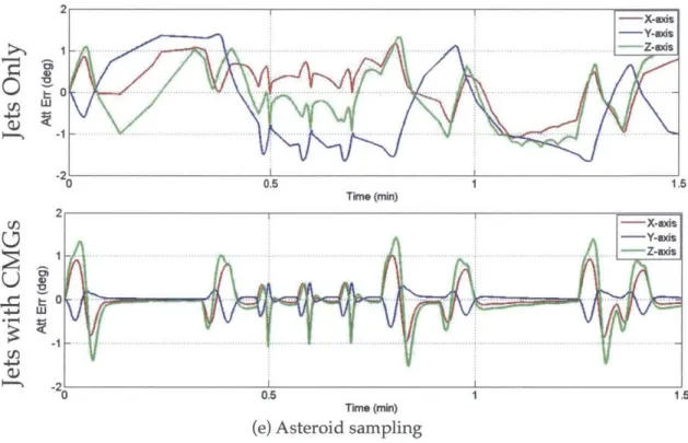
The simulation results include attitude error and fuel consumption. Figures 3.2a-e show the results for each attitude control system for the five mission building blocks.
Mission Building Block
Translation
Tool Retrieval
Attitude Correction
ISS Servicing EVA
Asteroid Sampling EVA
Table 3.1: Task Profiles
Mission Scenario
Astronaut traverses a series of 20 specified points in 3D space in 10 minutes (total distance: 50 m). No motion within the body reference frame.
Right arm reaches down to hip tool belt, retrieves Smart Power Tool (5.44 kg). [91 One minute later, right arm replaces tool back into the tool belt, and returns to initial position. Stationary at worksite.
Correction from an initial roll error of +7'. No motion within
the body reference frame.
Series of arm motions. Stationary at worksite. (This motion profile is not meant to accurately depict a specific servicing task, rather to encompass a broad range of arm motions and repetition.)
Hammer (0.91 kg) retrieval, three hammer blows to asteroid surface, left hand retrieves dislodged sample, hammer returned, sample bag retrieved, sample placed in bag, returned to tool belt. Stationary at worksite.
For the translation mission building block (Fig. 3.2a), the added CMG array offers several degrees of extra rotational stability and much less "bang-bang" jet control. The attitude control in the jets-and-CMGs case present just a slight disturbance that is quickly compensated, whereas the jets-only case reaches higher errors and has continuous oscillation of about 4 degrees.
Apart from purely exploratory missions, almost every EVA will include some tool use, making tool retrieval a very common task. The tool retrieval building block plots in Fig. 3.2b illustrate similar results to the translation block
-attitude oscillates with the jets overcorrecting and compensating time and again. The MAJIC control system quickly cancels out the disturbance torques, enabling the astronaut to use both hands for tasks without needing to hold onto anything for stability.
The differences between the two control system responses when completing an attitude correction maneuver (Fig. 3.2c) are slight, but still present. The CMG system compensates more quickly and settles out precisely at zero error, while the jets-only system takes a little bit longer and also gradually passes zero error and continues to accumulate error. If the timeline were extended, the jets plot would show a deadband between -2 and +2 degrees of attitude error, while the CMGs case keeps the attitude precisely at zero.
The top graph in Fig. 3.2d displaying the attitude error of the jets-only configuration during an ISS servicing EVA starts with a slowly oscillating error, but then shows zero error after a spike at 0.5 seconds. This is actually a product of the control algorithm used, and indicates that the attitude rate error became too high, forcing the controller to essentially ignore the attitude error in order to bring down the rate error. Thus, this ISS servicing task is effectively uncontrollable with the jets-only configuration. At about 80 seconds, the attitude error falls down to zero in the CMG case, indicating a large deviation in attitude error similar to the one that the jets case saw. However, the system recovers quickly, and within 10 seconds has regained complete control. The MAJIC control system, thus, is able to quickly and smoothly correct during an EVA task, even when there are large disturbances.
For this asteroid sampling task in Fig. 3.2e, the magnitude of the attitude errors are similar (~-2) across the two control systems; however, the jets-only configuration accumulates a significant drift offset from zero error. While the MAJIC system returns the astronaut to exactly zero error quickly and smoothly after each maneuver, the jets-only system is unable to do so.
Fuel consumption for each mission building block was also analyzed using the closed-loop simulation. Table 3.2 indicates a 100% fuel savings (no fuel usage) for tasks that require only attitude control. Even for the translation task,