HAL Id: tel-01138454
https://tel.archives-ouvertes.fr/tel-01138454
Submitted on 2 Apr 2015
HAL is a multi-disciplinary open access
archive for the deposit and dissemination of sci-entific research documents, whether they are pub-lished or not. The documents may come from teaching and research institutions in France or abroad, or from public or private research centers.
L’archive ouverte pluridisciplinaire HAL, est destinée au dépôt et à la diffusion de documents scientifiques de niveau recherche, publiés ou non, émanant des établissements d’enseignement et de recherche français ou étrangers, des laboratoires publics ou privés.
Helium mobility in advanced nuclear ceramics
Shradha Agarwal
To cite this version:
Shradha Agarwal. Helium mobility in advanced nuclear ceramics. Materials Science [cond-mat.mtrl-sci]. Université Paris Sud - Paris XI, 2014. English. �NNT : 2014PA112197�. �tel-01138454�
1
UNIVERSITE PARIS-SUD
ÉCOLE DOCTORALE : Modélisation et Instrumentation en Physique,
Energies, Géosciences et Environnement (MIPEGE)
Laboratoire JANNUS, DEN, SRMP, CEA-Saclay
Sciences des Matériaux
THÈSE DE DOCTORAT
soutenue le 22/09/2014
par
Shradha AGARWAL
Directeur de thèse : Patrick TROCELLIER Ingénieur de Recherche (CEA Saclay) Composition du jury :
Rapporteurs : Nathalie MONCOFFRE Directeur de Recherche CNRS (IPN Lyon) Guy TERWAGNE Professeur (Université de Namur)
Examinateurs : Frédérico GARRIDO Professeur (Université Paris-Sud Orsay) Ian VICKRIDGE Directeur de Recherche CNRS (INSP Jussieu)
Bernard BONIN Directeur de Recherche CEA (Saclay)
2
Acknowledgement
I would never have been able to finish my dissertation without the guidance of my laboratory
members, help from friends, and support from my family. The contributions of many different people, in their different ways, have made this possible. I would like to extend my appreciation especially to the following.
I would like to express my deepest gratitude to my advisor, Dr. Patrick Trocellier, for his excellent guidance, patience, and providing me with an excellent atmosphere for doing research. I would like to thank Sylvain Vaubauillon, who helped me in performing ion beam analysis experiments. This research would have not been possible without his help. I would also like to thank Dr. Thomas Jourdan and Dr. Alain Barbu for helping me in explaining the results from theoritical point of view. Special thanks to my friends Daniel Brimbal and Arunodaya Bhattacharya, from whom I learnt to use transmission electron microscope (TEM). It was impossible for me to obtain, interpret and understand TEM results without their help. I would like to thank Dr. Sandrine Miro, who gave her best suggestions related to the use of AGEING Code. Many thanks to Yves Serruys, Frederic Lepretre, Herve Martin and Eric Bordas for their availability and suggestions during irradiation experiments. Thanks for being with me from beginning until now. Special thanks also goes to Thomas Loussouarn, Gihan Velisa and Daniel Brimbal for keeping very friendly and lively ambiance in the office. It would have been lonely without them. I would highly acknowledge Emilie Jouanny, who gave her best to obtain results from Raman spectroscopy. I would also like to express my gratitude to Patrick Bonnaille and Sylvie Poissionnent for their help in scanning electron microscopy and nano-indentation experiments.
I would also like to thank Jean Luc Bechade and his team from SRMA (CEA) for their availability and help in various scientific issues. I would also like to thank Mario Le Flem from DMN (CEA) for providing excellent quality samples to us. I would also like to thank Frederico Garrido from CSNSM (CNRS-Orsay) for various scientific discussions and annealing experiments. I would also like to thank Hicham Khodja from LEEL (CEA) for µ- NRA experiments.
3
I would also like to thank Mr. Pascal Yvon, Head of Department of Nuclear Materials (DMN-CEA), Mr. François Willaime, Head of Physical Metallurgy Research Unit (SRMP-(DMN-CEA), Mme Lucile Beck, Head of Jannus Laboratory (CEA) to provide this opportunity to me. The experience has been an interesting and rewarding one. My very special thanks to François Willaime for sending me to various conferences and also for helpimg me finding a post-doctoral position. I would not forget to thank Patricia Matysiak and Martin Loge from SRMP who have always helped me regarding administrative issues.
Last but not least, I would thank God for the wisdom and perseverance. I would also like to thank my parents and brothers. They were always supporting and encouraging me with their best wishes. I would also like to thank Mr. Scateena George, my landlord for providing comfortable and friendly atmosphere during my stay for three years. Finally, I would like to thank my best friend, Arunodaya Bhattacharya for his unconditional support. He was always there cheering me up and stood by me through the good and bad times. My research would not have been possible without you all.
4
Table of Contents
Introduction ... 7
1. Context of the study ... 11
1.1. Nuclear fission energy ... 11
1.1.1. Generation IV initiative ... 14
1.1.2. Use of advanced nuclear ceramics in GEN IV reactors ... 16
1.2. Nuclear fusion energy ... 19
1.2.1. Use of advanced nuclear ceramics in fusion reactors ... 20
1.3. Helium in fission and fusion reactors ... 21
1.4. Helium interaction with nuclear materials and its consequences ... 23
2. State of Knowledge ... 27
2.1. Helium mobility in inorganic materials ... 27
2.1.1. Statistical details ... 28
2.1.2. Experimental methods for the study of helium behavior ... 31
2.1.3. Basic mechanisms of helium migration in inorganic solids ... 35
2.1.4. Main experimental data on helium migration in metallic substrates ... 37
2.1.5. Main experimental data on helium migration in non-metallic substrates ... 40
2.1.6. Conclusions ... 45
2.2. Radiation damage and gas diffusion in ZrC, TiC, and TiN ... 58
2.2.1. ZrC ... 58
2.2.2. TiC ... 65
2.2.3. TiN ... 69
3. Properties of Transition Metal Carbides and Nitrides ... 75
3.1. Crystallographic Structure ... 75
3.2. Nature of bonding ... 76
3.3. Details of the important properties ... 76
3.4. Variation of properties with M-to-X ratio (M: Ti or Zr & X: C or N) ... 80
A. ZrC ... 80
5
C. TiN ... 84
4. State of Knowledge ... 87
4.1. Radiation induced defects ... 87
4.2. Helium defects ... 90
4.2.1. Helium Diffusion ... 91
4.2.2. Helium Bubble Nucleation ... 92
4.2.3. Helium Bubble Growth ... 92
4.2.4. State of helium bubble ... 94
4.2.5. Helium bubble nucleation at extended defects ... 98
4.2.6. Homogeneous vs. heterogeneous nucleation ... 99
5. Experimental approach ... 103
5.1. Details of sample manufacturing ... 103
5.2. Implantation and annealing ... 105
5.2.1. Brief description of JANNUS Laboratory ... 106
5.2.2. Experimental details for the first set of experiment ... 108
5.2.3. Experimental details for the second set of experiment ... 111
5.3 Sample characterization ... 114
5.3.1. Nuclear Reaction Analysis with stationary 1 mm size deuteron beam ... 115
5.3.2. Nuclear reaction analysis with the scanning of 1 µm size deuteron beam ... 123
5.3.3. Transmission Electron Microscopy (TEM) ... 126
5.3.4. X-ray diffraction ... 126
5.3.5. Nano-indentation ... 128
5.3.6. Scanning Electron Microscopy (SEM) and Electron Microprobe ... 128
5.3.7. Raman Spectroscopy ... 128
6. Helium behavior under thermal environment ... 131
6.1. Helium behavior under thermal environment in TiC ... 131
6
6.1.2. Results and Discussion ... 132
6.1.3. General Discussion ... 144
6.1.4. Conclusion ... 147
6.2. Helium behavior under thermal environment in TiN ... 150
6.2.1. Reminder of the experimental approach ... 150
6.2.2. Results and Discussion ... 151
6.2.2.1. Specimens implanted with fluence F1 andannealed at various Ta ... 151
6.2.2.2. Comparison study between specimens with fluence F1, F2 & F3 ... 171
6.2.3. Conclusion ... 182
6.3. Helium behavior under thermal environment in ZrC ... 185
6.3.1. Reminder of the experimental approach ... 185
6.3.2. Results and Discussion ... 186
6.3.2.1. Specimens implanted with fluence F1 andannealed at various Ta ... 186
6.3.2.2. Comparison study between specimens with fluence F1, F2 & F3 ... 194
6.3.3. Conclusion ... 198
7. Helium behavior under radiation environment... 199
7.1. Reminder of experimental approach ... 199
7.2. Results and discussion ... 199
7.2.1. Results of sample characterization after damaging the samples ... 199
7.2.2. Results of NRA measurement ... 204
7.3. Conclusion ... 207
8. General Discussion ... 209
A. Helium release in TiC, TiN and ZrC ... 209
B. Helium diffusion in TiC, TiN and ZrC ... 213
C. Helium fluence effect ... 217
D. Helium behavior under radiation damage ... 218
Conclusions and Perspectives ... 220
7
Introduction
Access to reliable, sustainable and affordable energy is viewed as crucial to worldwide economic prosperity and stability. Given that nuclear power has very low carbon emission and that energy generation currently accounts for 66% of worldwide greenhouse gas emissions, nuclear energy is considered an important resource in managing atmospheric greenhouse gases and associated climate change.
While the current second and third generation nuclear plant designs provides an economically, technically, and publicly acceptable electricity supply in many markets, further advances in nuclear energy system design can broaden the opportunities for the use of nuclear energy. The fourth generation of nuclear reactors is under development. These new reactors are designed with the following objective in mind: sustainability, safety and reliability, economics, proliferation resistance. Out of six Generation IV systems namely, Gas-Cooled Fast Reactor (GFR), Lead-cooled fast reactor (LFR), Molten Salt Reactor (MSR), Sodium-Cooled Fast Reactor (SFR), Supercritical-Water-Cooled Reactor (SCWR), Very-High-Temperature Reactor (VHTR), this work is dedicated to identify specific fuel type that is compatible with gas-cooled fast reactor (GFR) in-core service conditions and could be extended to diagnose potential cladding material for SFR. The French strategy is mainly oriented towards the development of sodium-cooled fast reactors (SFR) and very slightly focused on GFR.
This dissertation is focused on the study of transition metal ceramics which are candidates for fuel coatings in GFR and have been considered as potential cladding materials for SFR. The specific fuel type in GFR should consists of spherical fuel particle made up of UC or UN, surrounded by a ceramic coating which provides structural integrity and containment of fission products. The most promising candidates for ceramic coatings are ZrN, ZrC, TiN, TiC & SiC due to a combination of neutronic performance, thermal properties, chemical behavior, crystal structure, and physical properties.
It is obvious that these ceramics (to be used as fuel particle coating for GFR or as cladding for SFR) would be exposed to energetic fission products from fuel such as heavy ions and neutrons. These high-energy neutron will knock the atoms in the surrounding materials and can induce (n, α) reactions, thus producing high concentration of helium atoms during and after reactor
8
operation. The helium atoms produced are energetic and can easily penetrate into the surrounding material.
Helium atoms are considered to be highly insoluble in previously studied structural nuclear materials. The accumulation of helium into solid matrix, can lead to the formation of bubbles, cavity, swelling, embrittlement etc. Helium can strongly induce grain boundary cavitation that can produce formation of inter-granular channels, which may serve as pathways for release of radioactive elements to the environment or lead to grain-boundary weakening and de-cohesion. Particularly in ceramics, large quantities of helium can also lead to dimensional changes and cracks due to over-pressurized helium bubbles. Therefore, study of helium behavior in advanced nuclear ceramics under high operating temperatures and extreme radiation conditions predicted for GFRs and SFRs is viewed as crucial by R&D team involved in the deployment of Generation IV energy systems.
This study can also be extended to fusion energy systems due to the presence of helium in fusion reactors and the use of TiC & TiN as coatings on materials used for permeation barrier against tritium. This thesis focuses on the study of helium mobility in transition metal ceramics under thermal and radiation environment and is mostly dedicated to investigate transition metal ceramics (TiC, TiN, ZrC). Due to the broad range of historic and novel nuclear applications of SiC such as advanced nuclear fuel forms, structural components for fission reactor systems, blanket structures for fusion energy systems and the immobilization of nuclear waste, SiC has been very widely studied in last two decades. Thanks to the abundantly available literature on SiC, a comparison between SiC and other transition metal ceramics has been drawn at the end of the thesis.
With the emergence of single, dual and triple ion beam irradiation facilities around the world, it is possible to simulate the radiation environment inside the reactors. It is possible to simultaneously implant gases (such as He, Ar, Kr, Xe etc.) and to damage material by one or two ions with different energy and masses. Along with this, it is also possible to heat (or cool) the material (with temperature ranging from 0 K to 800 K), thus allowing replication of real operating conditions inside the reactor. Exposing materials under this environment and their characterization, allows predicting material ageing, defect properties, microstructural evolution and structure-property relationship.
9
In this thesis, ion-implantation technique and material characterization techniques are used to study diffusion of helium in transition metal ceramics under thermal and extreme
irradiation environments. Our main aim during this thesis is:
● To calculate diffusion and migration energies of helium under different experimental conditions by applying theoretical models on experimental data.
● To investigate the microstructural evolution due to helium accumulation and conversely, identifying the role of microstructure such as grain boundaries, native vacancies and porosity
on helium accumulation.
● To know the role of helium introduction conditions on helium diffusion. ● To establish and validate an approach to calculate pressure built by helium gas inside the
bubbles and to verify if the pressure approaches mechanical stability limit. ● To understand ‘when and how ion beam analysis (IBA) could be more effective than
transmission electron microscopy (TEM)’ to study helium behavior in materials. ● To compare the helium effects in different ceramics (such as TiC, ZrC and TiN) for their
possible use in BISO (Bistructural-isotropic) or TRISO (Tristructural-isotropic) fuel forms for Gen IV reactors.
Following state-of-art material characterization tools are used namely, (1) IBA (Ion beam analysis), primarily NRA (nuclear reaction analysis) and RBS (Rutherford backscattering spectrometry) to know the positioning of helium atoms and other matrix atoms, (2) Raman
spectroscopy to determine different phases and to see the evolution of phases after implantation
and annealing, (3) TEM (transmission electron microscopy) to observe the microstructure evolution at nano-metric scale, (4) X-ray diffraction to determine the lattice swelling and other crystallographic information, (5) SEM (scanning electron microscopy) to analyze surfaces, (6)
Nano-indentation to test material hardness after irradiation, (7) Laser profilometry to measure
macroscopic swelling, (8) FIB (focused ion beam), electro polishing, PIPS (precision ion polishing system) to prepare electron transparent thin foils (~ 100 nm).
This thesis work has already led to three publications and other three publications are under process. They are planned to submitted by the end of this year. The predominant part of the thesis is based on learning to use various state-of-art material characterization tools, irradiation experiment, analyzing data and applying theoretical models for data interpretation.
This thesis is divided into eight chapters: Chapter one: In this chapter context of the thesis is provided.
10
Chapter two: Our state of knowledge on helium mobility in inorganic materials and radiation
effects in transition metal ceramics is presented. Chapter three: In this chapter, properties of transition metal ceramics are detailed.
Chapter four: Theoretical approach followed during this thesis is detailed. Chapter five: Experimental approach followed during this thesis is detailed. Chapter six: Results on helium mobility in transition metal ceramics under thermal
environment are presented and discussed. Chapter seven: Results on helium mobility in transition metal ceramics under radiation
environment are presented and discussed. Chapter eight: Finally, general discussion and conclusions are presented.
It is important to point out that the reference is provided at the end of each chapter. In chapter number two and six, reference is provided at the end of each sub-section.
11
Chapter 1
Context of the study
1.1. Nuclear fission energy
Nuclear power currently provides about 13% of electrical power worldwide, and has emerged as a reliable base load source of clean and economical electrical energy. In 2011, there were 435 nuclear reactors in operation worldwide, producing 370 GWe of electricity. Another 108
units or 108 GWe ofelectricity are forthcoming (under construction or on order), for a total of
543 units and 478 GWe of electrical capacity. Given that nuclear power has very low carbon
emission and that energy generation currently accounts for 66% of worldwide greenhouse gas emissions, nuclear energy is considered an important resource in managing atmospheric greenhouse gases and associated climate change [1].
Nuclear fission involves splitting a heavier nucleus into two lighter nuclei. The most common used fuel in most reactors is U-235. The spontaneous fission rate of U-235 is very slow; too slow to be of any use in a nuclear reactor. Therefore, a neutron is made to hit U-235 to induce fission and if a single U-235 nucleus fissions, the emitted neutrons can induce a fission in two or more U-235 nuclei, which each in turn can produce two or more, etc. If enough U-235 nuclei are close together, the process can increase rapidly, producing a lot of energy in a short time. This chain reaction can be described as:
+ → + + + (1.1) k is the number of neutrons released, generally between 2 & 3, and Qth is the energy generated
in the form of heat which is equal to ~ 200 MeV. This energy is distributed among the fission products X and Y, k number of neutrons, and radiation which is in the form of gamma rays and neutrinos.
12
The typical power densities in commercial nuclear reactor cores are ~ 50-75 MWth m-3, which
is nearly two orders of magnitude higher than the average power density in the boiler furnace of a large-scale coal power plant [1].
To maintain the constant rate of fission, control rods which are generally made of B4C are
used to absorb the neutrons. The reactor vessel contains the core (i.e., the uranium fuel) and water. The heated water in the reactor flows to a steam generator. The steam goes to the turbine causing that to rotate which then turns a generator, thus producing electricity. On the exit side of the turbine is a condenser. This condenser cools the steam and sends it to the environment. Nuclear plants are about 35 to 40% efficient; i.e., 35 to 40% of the heat generated in the reactor ends up as electricity; the rest is lost in the environment.
The neutrons produced by the fission process are too energetic to induce fission reaction of U-235 with a small cross section (σfast ≈ 1 .95 barns against σthermal ≈ 580 barns). Therefore, with
this energy of neutrons and with natural uranium as fuel (with only 0.7 % fissile nuclei), a steady rate of reaction is difficult to achieve. However, a constant rate of fission can be maintained if either total number of U-235 atoms (by enrichment of fuel) are increased or the energy of neutrons are bought closer to the energy of thermal neutrons to increase the cross section of absorption (by using moderators). Therefore, in a reactor, where the fast neutrons are moderated by elastic collisions with heavy water or light water and are thermalized is known as thermal reactors. However, a nuclear reactor in which the fission chain reaction is sustained by fast neutrons is known as fast reactor. Such a reactor needs no neutron moderator, but must use fuel that is relatively rich in fissile material when compared to that required for a thermal reactor. Over all, there are two main types of nuclear reactor in operation, characterized by the speed of the neutrons which induce fission:
a) Thermal reactors: These are the predominant kind, using slower neutrons to induce fission,
the basic fissile nuclide being U-235. Mainly, they include: 1. light water reactor (LWR)
2. boiling water reactor (BWR)
3. pressurized heavy water reactor (PHWR) 4. light water graphite-moderated reactor (LWGR) 5. gas-cooled reactor (GCR)
13
b) Fast reactors. In these less-common reactors, the fast neutrons are used directly to create
(breed) fissile nuclides from fissionable nuclides; most commonly Pu-239 is bred from U-238. Pu-239 is also used in nuclear weapons. It mainly includes:
1. fast-neutron breeder reactor (FBR)
All type of reactors are loosely grouped into generations describing the time period in which they were first used. Figure 1.1 shows time ranges correspond to the design and the first deployments of different generations of reactors and are discussed below:
Figure 1.1. Time ranges correspond to the design and the first deployment of different
generations of reactors [2].
In the next paragraph, a brief description of each generation of reactor has been provided:
1) First generation: The first power generation was introduced during the period 1950-1970
and included early prototype reactors such as Shipping port, Dresden, Fermi I in the USA and the Magnox reactors in the UK.
2) Second generation: The second generation includes commercial power reactors built during
1970-1990 such as LWRs, BWRs, and PWRs. In Canada, it includes the CANadian Deuterium Uranium heavy water moderated and natural uranium fuelled known as CANDU reactors. In Russia, this was the era of pressurized water reactor VVER-1000 and the RBMK-1000 of Chernobyl accident notoriety.
14
3) Third generation: The third generation started being deployed in the 1990s and is composed
of the Advanced Boiling Water Reactor (ABWR) and Advanced Light Water Reactor (ALWR) and the system 80+. These were primarily built in East Asian countries. New designs that are expected to be deployed by 2010-2030 include the Advanced Passive AP 600 and AP 1000. These are considered as evolutionary designs offering improved safety and economics.
4) Fourth generation: While the current second and third generation nuclear plant designs
provides an economically, technically, and publicly acceptable electricity supply in many markets, further advances in nuclear energy system design can broaden the opportunities for the use of nuclear energy. The fourth generation of nuclear reactors is expected to start being deployed in 2030. These new reactors are designed with the following objective in mind: sustainability, safety and reliability, economics, proliferation resistance.
1.1.1. Generation IV initiative
The Generation IV International Forum (GIF) was created in January 2000 by 9 countries and today has 13 members, all of which are signatories of its founding document, the GIF Charter. Argentina, Brazil, Canada, France, Japan, the Republic of Korea, South Africa, the United Kingdom and the United States signed the GIF Charter in July 2001. It was subsequ-ntly signed by Switzerland in 2002, Euratom1 in 2003, and the People’s Republic of China and Russian Federation in 2006.
A. Generation IV goals
The following goals were defined in the original GIF Charter:
1) Sustainability
● Generate energy sustainably and promote long-term availability of nuclear fuel. ● Minimise nuclear waste and reduce the long term stewardship burden.
15
● Excel in safety and reliability. ● Have a very low likelihood and degree of reactor core damage.
● Eliminate the need for offsite emergency response.
3) Economics
● Have a life cycle cost advantage over other energy sources. ● Have a level of financial risk comparable to other energy projects.
4) Proliferation resistance and physical protection
● Be a very unattractive route for diversion or theft of weapon-usable materials, and provide increased physical protection against acts of terrorism.
B. The Technology Roadmap
The Technology Roadmap (2002), defined and planned the necessary R&D and associated timelines to achieve these goals and allow deployment of Generation IV energy systems after 2030. This road mapping exercise was a two-year effort by more than 100 international experts to select the most promising nuclear systems. In 2002, GIF selected the six systems listed below, from nearly 100 concepts, as Generation IV systems:
1) Gas-Cooled Fast Reactor (GFR)
The GFR system is a high-temperature helium-cooled fast-spectrum reactor with a closed fuel cycle. It combines the advantages of fast-spectrum systems for long-term sustainability of uranium resources and waste minimization. The advantages of the gas coolant are that it is chemically inert (allowing high temperature operation without corrosion and coolant radio-toxicity) and single phase (eliminating boiling), and it has low neutron moderation.
2) Lead-cooled fast reactor (LFR)
LFRs are Pb or Pb-Bi-alloy-cooled reactors operating at atmospheric pressure and at high temperature because of the very high boiling point of the coolant (upto 1743 °C). The core is characterized by a fast-neutron spectrum due to the scattering properties of lead.
16
A molten salt reactor (MSR) is a class of nuclear fission reactors in which the primary coolant, or even the fuel itself, is a molten salt mixture. MSRs run at higher temperatures than water-cooled reactors for higher thermodynamic efficiency, while staying at low vapor pressure, liquid-fuelled MSR has been focused on fast spectrum.
4) Sodium-Cooled Fast Reactor (SFR)
The SFR is a Generation IV reactor project to design an advanced fast neutron reactor with the objective of producing a fast-spectrum, liquid sodium-cooled reactor. It allows a low-pressure coolant system and high-power-density operation with low coolant volume fraction in the core.
5) Supercritical-Water-Cooled Reactor (SCWR)
SCWRs are high temperature, high-pressure, light water reactors that operate above the thermodynamic critical point of water (374°C, 22.1 MPa). The reactor core may have a thermal or a fast-neutron spectrum, depending on the core design.
6) Very-High-Temperature Reactor (VHTR)
The VHTR is a next step in the evolutionary development of high-temperature gas-cooled reactors. It is a graphite-moderated, helium-cooled reactor with thermal neutron spectrum.
1.1.2. Use of advanced nuclear ceramics in GEN IV reactors
Out of the above selected Generation IV systems, the use of advanced nuclear ceramics has been validated for GFR, SFR and VHTR.
The French strategy is mainly oriented towards the development of sodium-cooled fast reactors and in a less extent towards GFR option [3]. Then, refractory ceramics have been considered as potential cladding materials for SFR [4].
Identification of a specific fuel type and fuel element/fuel assembly that is compatible with gas-cooled fast reactor GFR in-core service conditions is a key part of the overall goal of developing a practical version of a gas-cooled fast reactor. Current gas reactor fuel technology is not adaptable to a gas-cooled fast reactor. The categories of fuel with the highest potential
17
for success are carbide and nitride-base composite-type fuels. These fuels consist of a fissile phase dispersed within a refractory matrix.
The most promising candidates for GFR fuel matrix materials are ZrN, ZrC, TiN, and TiC, SiC due to a combination of neutronic performance, thermal properties, chemical behavior, crystal structure, and physical properties. These advanced ceramics are also considered as potential cladding material for SFR.
Normally, an advanced BISO (Bistructural-isotropic) fuel particle is considered for GFRs. This type of fuel form has a fuel kernel and two ceramic outer layers. The central kernel consists of a spherical fuel particle (consists of UC or UN) surrounded by a ceramic coating (TiC, ZrC, TiN, ZrN or SiC) which provides structural integrity and containment of fission products. In between the coating and the fuel, there is a buffer layer, which is also supposed to be made of (TiC, ZrC, TiN, ZrN or SiC). Buffer allows for changes in thermal expansion, swelling, and fission gas release pressure without creating an unacceptable amount of stress on the outer containment coating [5]. The fuel particle layers are shown schematically in figure 1.2.
The buffer layer is porous in order to reduce its stiffness and the resulting pressure on the coating and to accommodate released fission gases. It is composed of the same material as the coating. By using the same material for the buffer as the coating, there is reduced expansion mismatch and less chance of chemical incompatibilities. These advanced BISO fuel particles can be utilized by placing them in a ceramic matrix composed of the same material as the BISO fuel particles’ outer ceramic coating. With this design, there is only one major interface of different materials: the fuel and the buffer.
The new BISO micro fuel particle materials must meet a variety of criteria. Coatings with significant neutron absorption cross-sections cannot be used, thus excluding many candidates. The potential coatings must have high melting points (excess of 2000°C), adequate thermal
conductivity (>10 W/m-K) and toughness (>12 MPa-m1/2), and acceptable response to high
dose neutron damage (swelling <2% over service life (~80 dpa)). Thus, the categories of
materials with the highest potential for success for the GFR are carbide and nitride based ceramics [5,6]. The similar criteria is also expected for the candidates of cladding material in SFR.
18
Figure 1.2. One quarter of the cross section showing the layers of a BISO micro fuel particle
[5].
For VHTR reactor, use of TRISO fuel has been considered. Tristructural-isotropic (TRISO) fuel is a type of micro fuel particle which consists of a fuel kernel composed of UOx (some-
times UC or UCO) in the center, coated with four layers of three isotropic materials. The four layers are a porous buffer layer made of carbon, followed by a dense inner layer of pyrolytic carbon (PyC), followed by a ceramic layer of SiC to retain fission products at elevated temperatures and to give the TRISO particle more structural integrity, followed by a dense outer layer of PyC (see figure 1.3). In VHTRs (TRISO) fuel, ZrC will perhaps replace SiC. ZrC enables an increase in power density and total power level with the same coolant outlet temperature. Under accident conditions, historical data suggest that the ZrC-TRISO fuel may be more robust than traditional SiC-TRISO fuel, however lot of research projects are planned in near future to conclude this.
19
Figure 1.3. TRISO fuel particle showing fuel as well as ceramic coating [7].
1.2. Nuclear fusion energy
Fusion power is the power generated by nuclear fusion processes. Fusion happens when two (or more) nuclei come close together and forms a heavier one. In light fusion reactions, some of the mass is lost in this process. It is converted into energy through Einstein's mass-energy equivalence formula E = mc2.
To fuse atoms, it is necessary to overcome the repulsive Coulomb force. To overcome this "Coulomb barrier", the atoms must slam together at high speeds with high kinetic energy. The easiest way to do this, is to heat the atoms. Once an atom is heated above its ionization energy, its electrons are stripped away, leaving just the bare nucleus: the ion. Most fusion experiments use a hot cloud of ions and electrons. This cloud is known as a plasma. Most fusion reactions produce neutrons, which can be detected and degrade materials.
The fuel for fusion reactors will be a combination of deuterium and tritium. The reaction of deuterium with tritium produces alpha-particles and 14.1 MeV neutrons by the following equation:
20
where D and T are deuterium and tritium respectively. The leading designs for controlled fusion research use magnetic (tokomak design) or inertial (laser) confinement of a plasma. Both approaches are still under development and are years away from commercial operation in which heat from the fusion reaction is used to operate a steam turbine which drives electrical generators, as in existing fossil fuel and nuclear fission power stations.
1.2.1. Use of advanced nuclear ceramics in fusion reactors
Tritium as a fuel is difficult to handle and transport. During the tritium breeding and fusion reaction, there is the potential for permeation of the tritium through the materials containing it and for its release to the environment. Therefore, materials with a low permeability for tritium are being considered as barriers to prevent the loss of tritium from fusion plants. There are a few metals with relatively small values of permeability, but as a whole, metals themselves are not good barriers to the transport of tritium. Ceramics, on the other hand, are typically very good barriers if they are not porous. In most cases, the low permeation is due to extremely low solubility of hydrogen isotopes in ceramic materials. Carbides, nitrides, aluminides, oxides
are studied very extensively to be used as barrier to tritium transport.
Bulk ceramics, such as silicon carbide, may one day be used as tritium permeation barriers, but most of the current barrier development is for coatings of oxides, nitrides, or carbides of the metals themselves [8]. TiN coatings are one of the most researched barriers because of their good adhesion and the ease of deposition. Titanium carbide has also been tested as a permeation barrier. Due to adhesion problems with direct deposition on steel, titanium nitride was used as an intermediate layer between the steel and titanium carbide. These carbides and nitrides are
low-activation, temperature-resistant, and radiation damage tolerant compared to most materials. This consideration as barrier was also due to the presence of light element carbon
and nitrogen in TiC, SiC and TiN. The collisions of the plasma with low mass carbon and nitrogen atoms help in less dissipation of heat, and thus maintains high temperature inside the plasma [9,10,11].
Last but not least, oxide-dispersed strengthened (ODS) alloys contains dispersed oxide carbide and nitride nanoparticles. ODS alloys exhibit very interesting thermo-mechanical properties and a promising radiation tolerance due to the multiplication of interfaces within the matrix [12,13,14,15].
21
1.3. Helium in fission and fusion reactors
There is large production of helium atom in fusion reactors due to tritium decay. Apart from this, neutrons are produced in both fission and fusion reactors by their respective nuclear reactions (see equation 1.1 and 1.2). These high-energy neutron will knock the atoms in the surrounding materials and induce (n,α) reactions such as:
+ → + (several MeV) (1.3)
Consequently, the surrounding materials in both fusion and fission reactor are expected to contain a high concentration of helium atoms during and after operation.
Most reactions between neutrons (n) and nucleus (M) are energy dependent. The reaction rate (here for (n,α) reaction) in a thermal reactor is a product of the average fission flux cross section (i.e. on the probability that a nuclear reaction (n,α) would occur) and the equivalent fission flux (here neutron flux). Many (n,α) reactions are exothermic, that is, they can be caused by neutrons of all energies down to thermal. It has been recognized in recent years that, because of the importance of helium production rates in reactor internals, lot of investigation have been done in order to find better cross section data. Table 1.1 presents the crossection data for (n,α) reactions to measure directly the helium content for the principle elements found in stainless steel.
Table 1.1. The values of cross section of (n,α) reaction for few elements [16]. Principle elements of stainless
steel
Cross section of (n,α) reaction in the elements (milli-barn)
1. Chromium 0.2 mb
2. Iron 0.23 mb
22
In fusion, the issue of gas production is likely to be a more significant problem than in fission because of the higher neutron fluxes and higher average neutron energies. For example, in figure 1.4 where a fission spectrum for a fuel assembly of a 3.8 GWt (gigawatts of thermal power) LWR-P4 reactor in Paluel, France, is compared to a fusion spectrum computed for the first wall (FW) of the 3.0 GWt DEMO concept reactor, the fluxes of neutrons per lethargy interval are greater in the fusion spectrum at all energies instead of thermal energies [17].
Figure 1.4. Comparison of the neutron-energy spectra in fission and fusion reactors. For
fission the average neutron spectrum in the fuel-assembly of a PWR reactor is shown, while the equatorial spectrum for the DEMO model of fusion reactor is shown [17].
Furthermore, whereas the bulk neutron energy in fission is in the 2 MeV range, for every deuterium-tritium fusion reaction in the plasma, a 14.1 MeV neutron is produced. And most of the gas-producing nuclear reactions exhibit a cross section threshold, which means that for incident neutrons below a particular energy the reaction either does not occur or has a very low probability.
23
Thus, in fusion, while the higher neutron fluxes compared to fission would increase the total number of reactions in irradiated components, the larger fraction of neutrons at higher energies would also tend to raise the proportion of those reactions which lead to helium gas production. For fusion reactor, the value of helium per dpa i.e. (He/dpa ≈ 10) where as in fast fission reactors He/dpa << 1. Here, dpa is displacement per atom.
But, in the present work, the energy of helium is kept around 3 MeV to simulate the energy of neutrons in fission reactors due to the predominant candidature of transition metal carbides and nitrides as coating or cladding material in GEN IV reactors. However, the information on helium migration parameter for fusion reactor conditions can be derived very easily from this work.
1.4. Helium interaction with nuclear materials and its consequences
The primary characteristic of He, which makes it significant to a wide range of irradiation damage phenomena, is that it is essentially insoluble in solids. Hence, in the temperature range where it is mobile, He diffuses in the matrix and precipitates to initially form bubbles, typically at various microstructural trapping sites. The bubbles can serve as nucleation sites of growing voids in the matrix and creep cavities on grain boundaries (GBs), driven by displacement damage and stress, respectively. Helium can severely degrade the material’s properties and an example is explained below.
Figure 1.5 shows the effects of high He as a function of lifetime-temperature limits in a fusion first wall structure for various irradiation-induced degradation phenomena [18].
24
Figure 1.5. Illustration of the materials design window for the fusion energy environment, as a
function of temperature [18, 19].
The above sketch shows a very broad-brush, qualitative description of some of the important He effect. On increasing temperature, helium degrades the material properties by precipitating into small bubbles followed by void swelling and further by grain boundary cavitation. With time, material properties under reactor condition (or strong irradiation condition) as a function of temperature deteriorate as follows:
At lower temperatures (red curve), irradiation hardening and loss of tensile uniform ductility
are severe, leading to low-temperature fast fracture embrittlement phenomenon. This is believed to be primarily the result of- He-induced grain boundary weakening, manifested by a very brittle intergranular (IG) fracture path, interacting synergistically with irradiation hardening.
At intermediate temperatures (blue curve), the incubation time prior to the onset of rapid swelling is controlled by growing voids form on He bubbles, and He accumulation. At high temperatures, (green curve) are primarily dictated by chemical compatibility,
25
degrade the tensile ductility and the other high temperature properties, primarily by enhancing grain boundary cavitation.
The above behavior is mostly noted in structural alloys. There are very few papers in the literature on helium behavior in transition metal ceramics. But mostly, surface changes like blister formation and similar bubble (or cavity) development leading to swelling and also crack formation in extreme conditions have been reported in these ceramics material. Precise details from bibliography on helium behavior in transition metal ceramics are presented in next chapter.
References
[1] S. J. Zinkle, G.S. Was Acta Materialia 61 (2013) 735-758.
[2] Technology Roadmap Update For Generation IV Nuclear Energy Systems – January 2014 issued by the OECD Nuclear Energy Agency for the Generation IV International Forum. [3] Clefs CEA 172, Juillet – Août 2012, pp. 12 – 21.
[4] M. Le Flem, Advanced Materials for Fuel Cladding in Sodium Fast Reactors: From Metals to Ceramics, 2011, www.neutron.kth.se/oldsite/MATGEN.../Le_Flem.pdf.
[5] A. Nosek, J. Conzen, H. Doescher, C. Martin, J. Blanchard, J. Nucl. Mater. 371 (2007) 288-303.
[6] Jian Gan, Mitchell K. Meyer, Robert C. Birtcher, Todd R. Allen, Journal Of Astm International, April 2006, Vol. 3, No. 4.
[7] http://eddiehonorato.wordpress.com/tag/triso-coated-fuel-particle/
[8] D.L. Smith, J. Konys, T. Muroga, V. Evitkhin, J. Nucl. Mater. 307–311 (2002) 1314–1322. [9] G.R. Hopkins, R.J. Price, Nuclear Engineering And Design/Fusion 2 (1985) I 11-143. [10] J. Luthin, H. Plank, J. Roth, Ch. Linsmeier, Nucl. Instrum. Meth. Phys. Res. B 182 (2001) 218-226.
[11] Tritium Barriers And Tritium Diffusion In Fusion Reactors R. A. Causey, R. A. Karnesky, C. San Marchi, Sandia National Laboratories, Livermore, CA, USA 2012 Elsevier Ltd.
[12] A. A. Popovich, J. Alloys Compounds 215 (1994) 169-173.
[13] Cheng-Guo Wang, Bao-Sen Qi, Yu-Jun Bai, Jun Wu, Jun-Fa Yang, Mater. Sci. Engin. A308 (2001) 292–294.
[14] C.Y. Chen, H. W. Yen, F. H. Kao, W. C. Li , C. Y. Huang, J. R. Yang, S. H. Wang, Mater. Sci. Engin. A 499 (2009) 162–166.
26
[15] P. Berthod, Mater. Sci. Technol. 25 (2009) 1003-1008. [16] I. R. Birss, J. Nucl. Mater. 34 (1970) 241.
[17] M.R. Gilbert, S.L. Dudarev, S. Zheng, L.W. Packer, J.-Ch. Sublet Ccfe-Pr (12) 02. [18] A. Molvik, A. Ivanov, G. L. Kulcinski, et al. Fusion Sci. Technol. 57 (2010) 369–394. [19] Y. Dai, G. R. Odette and T. Yamamoto, The Effects of Helium in Irradiated Structural Alloys, 2012, Elsevier Ltd.
27
Chapter 2
State of Knowledge
To start with the investigation on helium mobility in transition metal ceramics. It appeared important to study the available literature on two topics; firstly on helium mobility in materials to understand ‘in general the behavior of helium in materials’, secondly on understanding ‘the response of transition metal ceramics on gas implantation and ion irradiation’. Therefore, a very broad literature survey was conducted on these two topics before planning the experiments. Our state of knowledge on helium mobility in materials (particularly in inorganic materials) has led to the publication of a review paper. This paper presents the review of more than 250 papers. This review paper can be obtained from the citation given below:
A review on helium mobility in inorganic materials, P. Trocellier, S. Agarwal, S. Miro, Journal of Nuclear Materials 445 (2014) 128-142.
This chapter is divided into two parts:
Part 1: In the first section of the chapter, important features on helium mobility in inorganic
materials from our recently published review paper have been mentioned. It is important to
know that only important points from the publication are mentioned in this section.
Part 2: In the second section of the chapter, our state of knowledge on transition metal cera-
mics has been presented.
Part 1
2.1. Helium mobility in inorganic materials
This part of the chapter reviews the available literature devoted to the study of helium migration in inorganic solids from both the experimental and the theoretical point of view. The
28
available literature devoted to the study of helium migration in solids first contains some pioneering review papers published during the time period 1963–1996 [1–23].
2.1.1. Statistical details
Our broad survey of the literature devoted both to experimental and theoretical studies of helium migration in inorganic materials lead us to select a high number of interesting papers. All inorganic materials can be easily divided into metallic and non-metallic material. Among them, four main classes can be identified:
● Class I: experimental investigations on pure metals and alloys [24–80]; ● Class II: experimental investigations on non-metallic compounds [81–156]; ● Class III: theoretical calculations on metallic materials [45, 157–181, 182–211]; ● Class IV: theoretical calculations on non-metallic compounds [212–224].
A. Class I: Experimental investigations on pure metals and alloys
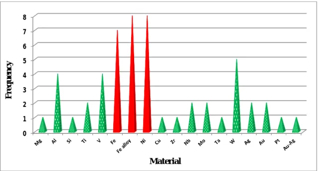
Helium diffusion was investigated in a large number of metallic materials. It includes Be [27],
C [30], Mg [28], Al [29,31,32], Si [33], Ti [28,34], V [35–39], Fe [40–47], Ni [40,48–54], Cu [55,56], Zr [40], Nb [37,56], Mo [57,58], Pd [59], Ag [25], Ta [60], W [61–66], Pt [67], Au [25], Ag/Au alloy [79], Fe-based alloys [40,48,68–77], and nickel-based alloys [48,78]. Papers from Thomas [24], Sciani [25], and Jung [26,27] published in the eighties and at the beginning of the nineties give an overview of experimental helium diffusion data obtained in fcc and other metals from Be to U.
The frequency distribution is plotted and shown in figure 2.1. This distribution obtained after wide literature survey shows that among all the studied metallic material for He effects, almost 55% of studied metallic material are Fe, Fe alloys, Ni (shown by red color in figure 2.1).
29
Figure 2.1. Results of the literature survey conducted on the experimental study of helium
migration in metals and alloys.
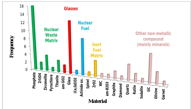
B. Class II: Experimental investigations on non-metallic compounds
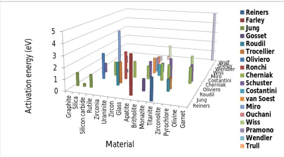
Studies of helium diffusion in non-metallic materials include natural and industrial glasses [81-106], crystalline and amorphous silica and quartz [33,107,108,140,141], silicon carbide [142-147], beryllium oxide [134,135], graphite and diamond [136,137], alumina [135], rutile [151], titanite or sphene (CaTiSiO5) [150,151], hydroxyapatite or fluorapatite (Ca10(PO4)6X2
with X = OH or F), and britholite (Ca4Nd6(SiO4)6X2) [109-125], monazite (rare earth
phosphate) [125], thorium phosphate [126], zirconia [117,118,152], spinel (MgAl2O4) [138],
zircon (ZrSiO4) [121], olivine ((Mg,Fe)2SiO4) [148,149], garnet (Ba3Al2(SiO4)3) [155],
aeschynite ((Y,Ca,Fe)(Ti,Nb)2(O,OH)6) [111], zirconolite (CaZr2O7), and pyrochlore
(Gd2Zr2O7) [117,118,153], zirconium nitride [154], uraninite (UO2) [127-133], plutonium
oxide [129]. Figure 2.2 illustrates this repartition.
Most of the above studied materials are classified as nuclear waste ceramics, glasses, nuclear fuels and inert fuel matrices. These four classes represent 70% of the above studied material. They are represented as green, red, blue and yellow for nuclear waste matrix, glasses, nuclear fuel and inert fuel matrix, respectively.
0 1 2 3 4 5 6 7 8 F re q u en cy Material
30
Figure 2.2. Results of the literature survey conducted on the experimental study of helium
migration in non-metallic materials.
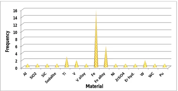
C. Class III & IV: Theoretical calculations on metallic and non-metallic materials
Modeling studies related to metallic materials mainly concern pure iron and iron-based alloys, i.e. more than thirty papers over fifty six.
Theoretical calculations on non-metallic compounds are rather present very little, i.e. thirteen papers. This rate corresponds to less than 15% of the total number of papers related to non-metallic materials and less than 19% of the total number of papers related to modeling. They are mainly focused on binary or ternary compounds: SiC [215, 218], UC [216], β-ErH2
[219], UO2 [220], ZrSiO4 [221], Ti3AlC2 [223], and more scarcely to complex substrate such
as sodalite (Na8Al6Si6O24Cl2) [213] or nanostructured materials such as metal/oxide interface
[222].
Figure 2.3 gives a statistical distribution on modeling studies devoted to helium migration in both metallic and non-metallic materials.
0 2 4 6 8 10 12 14 16 Ph o sp h a te Zr Si O 4 Zi rc o n o lit e Py ro ch lo re T it an it e a m -S iO 2 G la ss (C e, G d )O 2 A ct in id e o x. Sp in e l Zr O 2 W C a m-B2 O 3 G ra p h it e D ia mo n d Q u ar tz R u ti le So d al it e Si C O li vi n e G ar n e t F re q u en cy Material Nuclear Waste Matrix Glasses Nuclear Fuel Inert Fuel Matrix Other non-metallic compound (mainly minerals)
31
Figure 2.3. Results of the literature survey conducted on the modeling of helium migration in
inorganic materials.
2.1.2. Experimental methods for the study of helium behavior
The experimental configuration applied for the study of helium behavior in the near surface region of solids generally follows a three step approach:
(1) Helium incorporation in the material;
(2) Thermal annealing under fully controlled conditions; (3) Helium measurement.
Table 2.1 (presented on the next page) displays the most commonly adopted experimental conditions and gives the corresponding references. A brief summary will be given in the four following sub-sections in order to describe each of the three steps mentioned above.
I. Helium incorporation
Four options have been considered to introduce helium in bulk solids:
(1) Presence of radiogenic helium in natural minerals containing β-emitters as U or Th [150];
0 2 4 6 8 10 12 14 16 Fr e q u en cy Material
32
(2) Interaction between the solid surface and a He gas atmosphere up to saturation using thermal equilibration process or permeation through a porous membrane [82,102,103]; (3) Long term interaction of the solid surface with tritium. The β-decay of tritium produces
3He [77];
(4) Ion irradiation/implantation: This method is used in about 60% of the published
experimental papers. It includes:
● Direct helium ion implantation (near the surface or in depth) [110,121,147],
● High energy proton irradiation to produce helium by (p, α) spallation reactions [3,140, 238], ● 10B doping of the substrate followed by neutron irradiation to produce 4He according to the nuclear reaction 10B(n, 4He)7Li [31,144,145],
● 244Cm doping in order to detect its α-decay [153]. II. Thermal annealing step
After helium incorporation, thermal annealing is generally conducted ex-situ using a high temperature furnace [24, 52].
In the case of the application of Thermal Helium Desorption Spectrometry (THDS), annealing is conducted within the characterization device [57, 138].
III. Helium measurement
The most widely used characterization methods for helium measurement are mass spectro- metry in conventional or THDS modes for nearly 50% of the published experimental papers [47,95], and Ion Beam Analysis (IBA) for more than 30% of the published experimental papers [53]. Section IV gives more detail about IBA. Some special characterization configurations have also been developed and applied, for example:
● Atom probe field ion microscopy investigations by Amano on W [61]; ● Resistivity recovery measurements by Vassen on Pt [67];
● Chemical etching associated to gas chromatography by Chang-An Chen on stainless steel [77];
33
Material Step 1 Step 2 Step3 Reference
Al Spallation Thermal annealing Conventional mass spectrometry [29]
V He ion implantation Thermal annealing Alpha particle elastic scattering [35]
Mg, Ti
Body centered cubic metals He ion implantation Thermal helium desorption spectrometry
[26] [28]
W He ion implantation Thermal annealing Atom probe field ion microscopy [61]
Pt He ion implantation Thermal annealing Resistivity measurement [67]
Stainless steel Long term tritium storage Thermal annealing Chemical etching + gas chromatography [77]
W He ion implantation Thermal annealing Positron annihilation spectroscopy [63]
Fe and Fe-Cr alloy He ion implantation Thermal annealing Thermodesorption coupled with transmission electron microscopy
[44]
Silica glass Permeation Thermal annealing Conventional mass spectrometry [83 - 94,
102, 103]
Graphite He ion implantation Thermal annealing Proton elastic scattering [136]
Diamond Apatite
Native 4He Thermal annealing Conventional mass spectrometry [137]
[109]
Obsidian, basaltic glass Gas saturation Thermal annealing Conventional mass spectrometry [95]
Spinel He ion implantation Thermal helium desorption spectrometry [138]
ZrO2, britholite He ion implantation Thermal annealing Deuteron-induced nuclear reaction analysis [114, 115,
117 – 119, 124, 147,
152] Zircon, apatite, rutile,
titanite, monazite
He ion implantation Thermal annealing Deuteron-induced nuclear reaction analysis [121, 125, 149, 151] Fluorapatite He ion implantation Thermal annealing Heavy ion-induced elastic recoil detection analysis [110]
SiC 10B + neutron irradiation Thermal helium desorption spectrometry [144]
Zirconolite, pyrochlore 244Cm doping Thermal annealing Conventional mass spectrometry [153]
Fluorapatite, britholite, SiC He ion implantation Thermal annealing Deuteron-induced nuclear reaction analysis [120, 147] UO2
Nuclear glasses
He ion implantation Thermal annealing Deuteron-induced nuclear reaction analysis in coincidence
[131, 132, 146] [104, 105]
Thorium phosphate Radiogenic 4He Thermal annealing High sensitivity β-spectrometry [126]
Apatite Radiogenic 4He Thermal annealing Laser ablation depth profiling coupled with mass
spectrometry
[123] Table 2.1. Summary of experimental approaches developed to study helium migration in the near surface region of inorganic solids.
34
● THDS and Transmission Electron Microscopy (TEM) coupling by Ono on pure iron and Fe-Cr alloys [44];
● Positron Annihilation Spectroscopy (PAS) by Debelle on W [63];
● High sensitivity α-spectrometry by Özgümüs on thorium phosphate [126];
● UV laser ablation depth profiling coupled with mass spectrometry by van Soest on Durango apatite [123].
IV. Ion beam methods applied to helium migration study
The technique is based on high energy proton irradiation to produce helium via a spallation process and also consists in doping the material with 10B and then submitting to neutron irradiation. The required large scale facilities are, however, of limited access.
The main advantage of helium ion implantation (3He or 4He) lies in its versatility.
● One can modulate the implantation depth from the near surface (a few hundred of nanometers) to larger depth (several micrometers) by simply varying the energy.
● It is also possible to modulate the ion dose, for example in the range 5.0 x 10¹⁹ - 1.0 x 10²¹
ions/m2.
Nevertheless, the main drawback of ion implantation arises from the defect distribution introduced in the sample that may cause helium trapping and undesired deviations in the final helium measurements.
Ion Beam Analysis techniques have been applied to determine helium depth profiles in the near surface region of solids since the middle of the seventies. Four methods have been successfully considered:
(1) The deuteron-induced nuclear reaction 3He (d, p)α [34, 114, 115, 121, 226, 227, 230, 231]; (2) The proton elastic scattering 3He(p, p)3He and 4He(p, p)4He [136, 228, 229];
(3) The high energy 4He elastic scattering 4He(p, p)4He coupled with coincidence
spectrometry [35];
(4) The high energy Heavy Ion induced Elastic Recoil Detection Analysis (HI-ERDA) [110, 239].
35
High-energy alpha particle elastic scattering requires the use of a cyclotron to produce the incident helium ion beam (50 to 70 MeV). High energy Heavy Ion induced Elastic Recoil Detection Analysis requires high energy heavy ion beam with a kinetic energy about 1 MeV/mass unit [235,236,242].
3He and 4He depth profiling can achieve relatively good depth resolution (less than 50 nm)
typically on implantation depth of 1 µm [237]. Specific detection devices must be implemented both to improve the analyzed depth profile and to discriminate the contributions from the different target components to the resulting ERDA spectrum [237].
Deuteron-induced nuclear reaction on 3He is the most useful and widespread method. Helium
depth profiling is based either on the detection of the emitted protons or alpha particles through the 3He(d, p)4He nuclear reaction as a function of the incident deuteron energy. The Q-value of this reaction is very high, namely 18.354 MeV. The depth profile obtained by proton elastic scattering is affected by the scattering response of all the other elements contained in the target that are superimposed in the measured spectra.
2.1.3. Basic mechanisms of helium migration in inorganic solids A. Irradiation damage
The basic mechanisms of material damage build-up under irradiation such as point defects, defect clusters, and helium accumulation effects are carefully detailed in recent review papers by McHargue, Zinkle, Chroneos, and Dai [244-247]. A good knowledge of the properties of single helium atoms and small clusters in a metal or a ceramic lattice is the basis for any fundamental understanding of helium effects. The next step is the nucleation and growth of bubbles which then finally lead to the macroscopically observable material deteriorations. Looking at advanced nuclear materials (metallic alloys, ceramics and composites) for applications to Generation IV fission reactors and fusion energy systems, all will be facing the same radiation degradation phenomena: low temperature hardening and embrittlement; radiation-induced segregation or precipitation; radiation-induced phase stability; void swelling; irradiation creep; high temperature helium embrittlement; surface blistering and exfoliation; and irradiation-assisted corrosion or stress corrosion cracking [8,14,244,245].
36
B. Mechanisms of helium migration in metallic materials
In metallic substrates, helium migration mainly occurs by the following physical mechanism [246]:
(1) The migration of interstitial helium atoms occurs generally with very low migration energy, less than 0.1 eV;
(2) Substitutional helium atoms may diffuse by a conventional vacancy-exchange mechanism. This vacancy mechanism can be considerably influenced by the vacancies and interstitials produced by the atomic displacements. The measured activation energy is generally close to 1 eV;
(3) Substitutional helium atoms may also migrate by dissociation mechanism. In this case the associated activation energy is higher than 2.0 eV.
C. Mechanisms of helium migration in non-metallic materials
In most ceramic systems, three main mechanisms to describe atom diffusion are similar to metallic system. The mechanism of atomic helium diffusion are [245]:
(1) The interstitial mechanism in which an interstitial atom jumps from one interstitial site to a neighboring one;
(2) The vacancy mechanism in which a substitutional atom jumps to a neighboring vacancy; (3) A mechanism in which an interstitial atom displaces an atom from its normal
substitutional site. Then, the substitutional atom moves to a free interstitial site.
The major physical mechanisms able to affect helium migration are overall the same, i.e. trapping/detrapping processes by/from point or extended defects; interactions with grain boundaries, and growth of bubbles.
However, irradiation-assisted corrosion or stress corrosion cracking will only be of concern in metallic systems. And radiation-induced amorphization only concerns ceramic materials such as silicon carbide or SiCf/SiC composite, waste immobilization matrix, coating layer and
ceramic nanophases embedded in metallic substrate such as ODS (Oxide Dispersion Strengthened alloys).
37
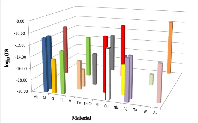
2.1.4. Main experimental data on helium migration in metallic substrates
According to the reviewed literature concerning the mobility of helium in metals and alloys, activation energy data are gathered in figure 2.4 and diffusion coefficient values are gathered in figure 2.5. It is important to note that the experimental configurations adopted by the different research groups may vary to a large extent in terms of temperature range explored, helium content introduced in the substrate, chemical composition and microstructure of the substrate. We have plotted the values extracted from studies having different experimental configuration on the same material. For eg., in figure 2.4. red, yellow, green, purple represents nickel, iron, vanadium and Fe-Cr, respectively.
Figure 2.4. Overview of activation energy values determined for migration of helium in metals
and alloys. Here, red, yellow, green, purple represents nickel, iron, vanadium and Fe-Cr, respectively. Jung Terentyev 2 Lefaix Smidt Jr Philips 0 1 2 3 4 5 6 Mg Al Ti V Fe Fe-Cr Ni Cu Nb Ag Ta W Au A ct iv at io n e n e rg y (e V ) Material Jung Sciani Terentyev 1 Terentyev 2 Morishita 1 Morishita 2 Lefaix Debelle Zielinski Smidt Jr Lewis Vassen Philips Adams Zhang
38
Figure 2.5. Overview of diffusion coefficient values determined for migration of helium in
metals and alloys.
A. Pure iron and iron-based alloys
A very detailed work based on THDS measurement by Morishita allows the discrimination of the different trapping sites in pure iron and to determine their energy parameters [42]. Several features were identified on the THDS spectrum for a pure iron sample implanted at 8 keV and they appeared to be dose dependent:
● A sharp peak at 450 K corresponds to helium atoms desorbed from single vacancy located near the surface. It is characterized by a dissociation energy about 1.6 eV;
● A broad peak located in the interval 750-800 K associated with helium atom desorption from small Hen-Vm clusters with a typical dissociation energy of 2.7 eV;
● A broad peak located in the interval 800 - 1000 K present at high helium dose (> 5 x 10¹⁷ m
-2). It is attributed to helium atoms desorbed from He
n-Vm clusters. The calculated dissociation
energy varies in the range 2.2-3.0 eV;
● A sharp peak at 1100 K corresponding to the desorption of helium from a single vacancy. The corresponding dissociation energy is 3.8 eV;
-20.00 -18.00 -16.00 -14.00 -12.00 -10.00 -8.00 Mg Al Si Ti V Fe Fe-Cr Ni Cu Nb Ag Ta W Au lo g10 (D ) Material
![Figure 1.1. Time ranges correspond to the design and the first deployment of different generations of reactors [2]](https://thumb-eu.123doks.com/thumbv2/123doknet/14718085.750594/14.918.139.785.407.684/figure-ranges-correspond-design-deployment-different-generations-reactors.webp)
![Figure 1.2. One quarter of the cross section showing the layers of a BISO micro fuel particle [5]](https://thumb-eu.123doks.com/thumbv2/123doknet/14718085.750594/19.918.238.685.97.507/figure-quarter-cross-section-showing-layers-biso-particle.webp)
![Figure 1.3. TRISO fuel particle showing fuel as well as ceramic coating [7].](https://thumb-eu.123doks.com/thumbv2/123doknet/14718085.750594/20.918.149.771.98.386/figure-triso-fuel-particle-showing-fuel-ceramic-coating.webp)
![Figure 1.5. Illustration of the materials design window for the fusion energy environment, as a function of temperature [18, 19]](https://thumb-eu.123doks.com/thumbv2/123doknet/14718085.750594/25.918.240.694.98.455/figure-illustration-materials-design-window-environment-function-temperature.webp)
![Figure 2.8. Swelling behavior of zirconium carbide during neutron radiation as reported by Keilholtz [4]](https://thumb-eu.123doks.com/thumbv2/123doknet/14718085.750594/61.918.194.668.118.560/figure-swelling-behavior-zirconium-carbide-radiation-reported-keilholtz.webp)
