Publisher’s version / Version de l'éditeur:
Vous avez des questions? Nous pouvons vous aider. Pour communiquer directement avec un auteur, consultez la première page de la revue dans laquelle son article a été publié afin de trouver ses coordonnées. Si vous n’arrivez pas à les repérer, communiquez avec nous à [email protected].
Questions? Contact the NRC Publications Archive team at
[email protected]. If you wish to email the authors directly, please see the first page of the publication for their contact information.
https://publications-cnrc.canada.ca/fra/droits
L’accès à ce site Web et l’utilisation de son contenu sont assujettis aux conditions présentées dans le site LISEZ CES CONDITIONS ATTENTIVEMENT AVANT D’UTILISER CE SITE WEB.
Student Report (National Research Council of Canada. Institute for Ocean Technology); no. SR-2007-03, 2007
READ THESE TERMS AND CONDITIONS CAREFULLY BEFORE USING THIS WEBSITE.
https://nrc-publications.canada.ca/eng/copyright
NRC Publications Archive Record / Notice des Archives des publications du CNRC :
https://nrc-publications.canada.ca/eng/view/object/?id=2aae1c7f-68bf-44ac-9599-d03f0b1e02eb https://publications-cnrc.canada.ca/fra/voir/objet/?id=2aae1c7f-68bf-44ac-9599-d03f0b1e02eb
NRC Publications Archive
Archives des publications du CNRC
For the publisher’s version, please access the DOI link below./ Pour consulter la version de l’éditeur, utilisez le lien DOI ci-dessous.
https://doi.org/10.4224/8894909
Access and use of this website and the material on it are subject to the Terms and Conditions set forth at
Modem pool redesign using Linux
Jessome, S.
National Research Council Conseil national de recherches
Canada Canada
Institute for Ocean Institut des technologies
Technology océaniques
MODEM POOL REDESIGN USING LINUX
SR-2007-03
Sean Jessome
DOCUMENTATION PAGE
REPORT NUMBER
SR-2007-03
NRC REPORT NUMBER DATE
April 2007
REPORT SECURITY CLASSIFICATION
Unclassified
DISTRIBUTION
Unlimited
TITLE
Modem Pool Redesign Using Linux
AUTHOR(S)
Sean Jessome
CORPORATE AUTHOR(S)/PERFORMING AGENCY(S)
Institute for Ocean Technology Memorial University of Newfoundland
PUBLICATION
SPONSORING AGENCY(S)
IOT PROJECT NUMBER
421020
NRC FILE NUMBER KEY WORDS
Modem, Network, Linux, RADIUS
PAGES 12 FIGS. 15 TABLES SUMMARY
This report details the reconstruction of IOT’s modem pool using a Linux based computer to perform the same function as the existing system. The idea is that the experience is going to remain the same to the end-user but the system will be easier to update for system administrators.
ADDRESS National Research Council
Institute for Ocean Technology Arctic Avenue, P. O. Box 12093 St. John's, NL A1B 3T5
TABLE OF CONTENTS
1.0 Introduction ...1
1.1 Font Convention ...1
1.2 Censoring ...1
2.0 Setting the Foundation ...1
2.1 Installing the OS ...1
2.2 Kernel Source and Headers ...1
2.2.1 Kernel Source ...2
2.2.2 Kernel Headers ...2
2.3 Default Drivers ...2
2.3.1 Locating the Driver ...2
2.3.2 Renaming ...2
2.3.3 Changing Permissions ...3
2.4 Ncurses ...3
2.5 System Updates and Kernel Compile ...3
2.5.1 Compiling the Kernel ...3
3.0 Installing the Harware ...4
3.1 Downloading and Installing the Driver ...4
3.2 Configuring the Driver ...4
3.2.1 rc.d ...5
3.3 Installing the Hardware ...5
3.3.1 Internal Hardware ...5
3.3.2 External Module ...5
3.3.3 Initial Hardware Test ...6
4.0 Testing the Hardware ...6
4.1 Port-to-Port ...6
4.1.1 dgaptest ...6
4.2 Minicom ...6
4.2.1 Setting up Minicom ...6
4.2.2 Using Minicom to Configure and Modem ...7
4.2.3 Dialing Out ...7 5.0 Software Setup ...7 5.1 Mgetty ...8 5.1.1 mgetty.config ...8 5.1.2 login.config ...8 5.1.3 inittab ...9 5.2 radiusclient ...9 5.2.1 Servers ...9 5.2.2 Port-Id-Map...9 5.2.3 Radiusclient.conf ...10 5.2.4 Radtest ...10 5.3 PPP ...11 5.3.1 General Options ...11
5.3.2 Port Specific Options ...11
7.0 Testing ...12
8.0 Summary ...13
LIST OF FIGURES Figure 1: Finding the Driver ...3
Figure 2: Dmesg Output showing Digiboard ...5
Figure 3: Digi Hardware setup guide ...5
Figure 4: Minicom startup screen ...7
Figure 5: Software Layout Flowchart ...8
Figure 6: Mgetty.config ...8
Figure 7: AutoPPP inside login.config ...9
Figure 8: inittab entries ...9
Figure 9: RADIUS Server file ...10
Figure 10: RADIUS Port-mapping ...10
Figure 11: radiusclient.conf ...10
Figure 12: Radtest output ...11
Figure 13: PPP Options ...11
Figure 14: Contents of options.ttya03 ...11
Figure 15: System Control File ...12 APPENDICIES
1. Introduction:
The Institute for Ocean Technology has in operation a modem pool so that employees without residence Internet access can dial into our designated line and take advantage of the resources they would get in the office. The current system is antiquated and difficult to support due to the fact that updated versions the operating system currently in use no longer supports the hardware used.
This report details the process of building a computer that can replace the modem pool server currently in operation. The materials we need before we get started are: A PC with a formatted hard-drive, a copy of Debian Linux 3.1, a Digi PCI concentrator card and the external multi-serial adapter or Digiboard to go with it. Covered below are the steps taken that resulted in a successfully operating system. First, the installation and pre-configuration of Linux on the machine to ensure the rest of the steps proceed smoothly. Followed by the installation of the Digiboards driver software known as dgap- for DiGi AccelePort. Once this hardware is activated then it is a matter of attaching a modem and configuring the computer to answer incoming calls and validate the user against the Windows login database for the Institute. After this is done, an IP address can be assigned to the computer behind the incoming call and allowing Internet access.
1.1 Font Convention:
-General Text and Instruction will be written in Times New Roman -Keyboard commands will be in Courier
-Screen output will be in monospace, outlined in black.
1.2 Censoring
Sensitive Information, such as passwords and secret words will be hidden in the general edition and provided to the Computer Systems Group separately.
2. Setting the foundation: 2.1 Installing the OS
Before installing Debian, we need to ensure that the Digi PCI card is not in the machine yet. Then we proceed to do a standard install of the OS – not covered in detail in this report – choosing to use the file server and desktop packages when prompted. An essential step at this point is to setup a static IP address so that the network can uniquely identify this machine consistently.
2.2 Kernel Source and Headers
With the OS installed we now need to install the kernel source and kernel headers. To do this we open up a terminal window and become the super-user using the su command and appropriate password.
2
2.2.1 Kernel Source:
The kernel source is important on any machine where software is going to be compiled from its own source code. We need to know what version of the kernel we’re using and then download its source. Then we need to go to /usr/src and unzip and un-tar the downloaded file. This will create a folder called kernel-source-2.4.27. And finally we create a symbolic link to that folder under the name linux so that a compiling program can simply look for this folder - independent of version number.
uname –r
apt-get install kernel-source-2.4.27 cd /usr/src
bzip2 –dc kernelsource2.4.27.tar.bz2 | tar xvfz -ln –s kernel-source-2.4.27 linux
2.2.2 Kernel Headers:
Now we will install kernel headers, for completeness’ sake, although they perform the same role as the source, but in a more compact form – only displaying the names of the included files and not the files themselves.
apt-get install kernel-headers-2.4.27-2-386
2.3 Default Drivers.
The next step of this project is to hide the default Multi-port serial card driver so that it doesn’t automatically load when we put in the Digi card. This step is very important and failure to do will cause errors on boot-up and non-functionality of any serial ports connected to the Module.
2.3.1 Locating the Driver
This will take us to the directory with any drivers that are built into the kernel for character devices (the Digi card). We’ll perform a search to locate the existing driver that is under the name epca.o
cd /lib/modules/2.4.27-2-386/kernel/drivers/char ls epca*
2.3.2 Renaming
mv epca.o epca.dont.o
Now, if we do an ls epca* we’ll see Figure 1. This little switch tricks the computer into thinking the epca driver isn’t there and it goes looking for an alternative.
2.3.3 Changing Permissions
Just to make absolutely sure this file doesn’t get used unless it’s absolutely needed by a system administrator, we change its permissions so that root will have to manually change them back in order to anyone to use the file.
chmod 000 epca.dont.o
2.4 Ncurses
The next step in the process is to install a library of files known as ncurses, “new curses” that allows Text User Interfaces to be contructed. The dgap driver needs to compile against some of the files in this library since one of the analysis tools is based on these scripts. There is a library available through apt-get under the name libncurses5-dev, but – unsure of whether this was enough – a full ncurses5.6 package was downloaded from the developers website in .tgz format. This is installed the same way that the dgap driver will be installed a few steps later.
2.5 System Updates and Kernel Compile.
Now that we’ve got a base in place it’s time to get it firmed up before we start building on it. First thing to do is update the system.
apt-get update apt-get upgrade
2.5.1 Compiling the Kernel
The system is up to date and so now we can prepare the kernel. This step takes the source we just downloaded and breaks any dependencies it might already have. Then it copies the current configuration of the running kernel, with that configuration it rebuilds the module dependencies. When the driver gets installed, it will be referencing these files, so this step ensures that everything is aligned correctly.
cd /usr/src/linux make mrproper
make oldconfig (it still prompted for some input, just accept the defaults) make dep
4
3. Installing the Hardware:
With the system prepared we can now download and install the dgap driver then put the hardware in the machine.
3.1 Downloading and Installing the Driver
From the Digi website (http://www.digi.com) we need to locate the driver for the card we’re about to put in. Digi has changed the naming system of their devices since ours was manufactured, so, we’re looking for the AccelePort Xem model of serial devices. There are two formats available for downloading version 1.3-6 (the latest) of the dgap driver – .rpm (Redhat Package Manager file) and .tgz (Compressed tarball file) – we chose the .tgz that downloaded under the name 40002347_c.tgz.
By default this will download to /home/*username* so that’s where it is on this system.
We can’t use the .tgz as it is, it has to be expanded – analogous to unzipping a file in Windows. And, we’re also going to untar it to a directory in /usr/local.
cd /usr/local tar xvfz /home/jessomes/40002347_C.tgz cd dgap-1.3/ ./configure make all make install make postinstall
(This seems to be unique to this particular software installation – other programs might not have the postinstall step.)
3.2 Configuring the Driver
The script from the last step tells us to run mpi – it has a few steps it is in a section to itself. Below is the flowchart for the correct selections.
mpi
-Launch the Config/Setup Program -Config script =>Yes
If there’s an old dgap config file, it will be detected here and you will be asked to save it as a backup. If this option is here, choose yes.
-ID letters picked for you => Yes. -1 Adapter
-AccelePort Xem PCI -1 Module
-8 Ports
-Are ports ttya01-ttya08 acceptable? => Yes -Altpin set to default (off) => Yes.
Say yes to the last screen and the driver will load.
3.2.1 rc.d
The driver itself is loaded by /etc/init.d/dgap. We need to ensure that this entry exists in the boot cycle. The command used to do this is:
update-rc.d dgap defaults
3.3 Installing the Hardware. 3.3.1 Internal Hardware
The hardware can now be installed inside the machine. After shutting down the machine, inserting the Digi card and closing the machine, we can see if the computer likes the new piece we gave it by booting back up. If we go back to the command line and type: dmesg | less. You should see something similar to Fig 2 at the bottom of end of the list.
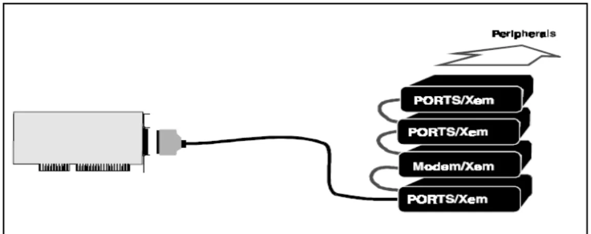
3.3.2 External Module
The external module can now be installed. First we need to shut down the computer because the unit receives power through the External Bus Interface (EBI) cable and could become damaged otherwise. A full setup looks something like Fig 3
Figure 3 Figure 3 Figure 2
6
Although in our cause only the bottom module would be present and would have 4 peripheral modems attached to it. An important thing to note here is that the EBI cable plugs into the slot marked ‘IN’ on the module. Once that is hooked up, we can boot the computer and perform some tests.
3.3.3 Initial Hardware Test
Get to a command line and log in as root. The first command we’re going to try is dpa; this utility is the Digi Port Authority. It provides a graphical representation of which signals are active on any of the serial ports on the module. At this point there aren’t any signals because there aren’t any modems plugged in, but this confirms that the module is in place and ready for operation.
4. Testing the Hardware: 4.1 Port-to-Port
Using a null modem cable – with several adapters so that it has 25 pin female connectors on both ends – connect any two ports together. For simplicity, lets choose 1 and 2. The names of these ports in the system are ttya01 and ttya02 respectively.
4.1.1 dgaptest
Dgaptest is a somewhat self-explanatory utility that provides you with the ability to do port-to-port and loopback tests on the Digiboard. Just select the test you want to do (port-to-port), the ports you want to do it with (ttya01, ttya02) and how many times you want to do it (10). The output, if everything went well, should be simply 10 lines of “passed.” You can repeat this process with varied port combinations to ensure all the ports are operational.
4.2 Minicom
4.2.1 Setting up Minicom
Another useful tool is Minicom, it acts as a terminal interface between the computer and the attached modem. The computer won’t have this by default, so we have to:
apt-get install minicom.
In order to use the program, we need to plug a modem into one of the serial ports on the Digiboard using a standard serial cable. In the example below, the modem is attached to port 3, i.e. ttya03. In order to get Minicom talking to the modem we need to tell it where to look, so we enter into setup mode using the –s tag.
minicom –s
By default this will be set to ttyS1, change it to ttya03, press enter to get back to the main menu and select save setup as... I chose the mnemonic name a03. Now we exit the configuration.
4.2.2 Using Minicom to Configure a Modem
First we need to start Minicom with its new characteristics using: minicom a03
If all went well, your screen should resemble Fig 4, followed by a blinking cursor. This – the AT string in particular – tells us that the modem can talk to the computer via the Digiboard. This is also where we can change the modem settings, if any need to be changed. We only need to change a few things.
ATS00=0 The modem won’t answer the phone (we want the computer to). ATM0 For our sanity, this disables the modem speaker.
AT&W0 Saves the current settings to the default. For a full list of AT commands see appendix A.
4.2.3 Dialling Out
You can also use Minicom to test the phone line. We made sure we could dial out by calling MUN’s modem pool.
ATDN97372168
A welcome and a command prompt confirm a successful dial attempt.
5. Software Setup:
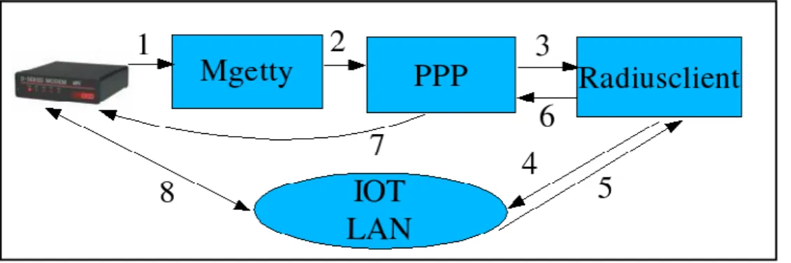
We need a few programs to help with the back end processes that need to happen for this to work (Figure 5): Mgetty, ppp, radiusclient1 and freeradius. Mgetty is set to listen to the Digi ports for a modem to become active (1) and sends its information straight to PPP (2) (Point-to-Point Protocol) for authentication. We check the usernames and passwords against the database that already exists (3,4,5). This is what RADIUS does; it
8
then returns the information to PPP (6), which then provides IP information to the modem
(7). Allowing the device to be connected to the Local Network (8).
5.1 Mgetty:
Mgetty is a program, similar to other “getty’s”, that listens for TTY (TeleTYpewriter) inputs. Any device that connects using a serial line is classified as a TTY device. In order to use the program, however, it needs to be installed.
apt-get install mgetty
5.1.1 mgetty.config
This file is where Mgetty can be configured to respond to particular ports and to specify and hardware requirements
cd /etc/mgetty vi mgetty.config
For every port with a modem, add a section (Fig 6) at the bottom.
5.1.2 login.config
This file dictates which program should be called to initiate the login procedure once the modem has been connected.
Figure 6 Figure 5
vi login.config
Ensure that the AutoPPP line is uncommented and we’re going to enable the plug-in that lets it talk to the radius server. Figure 7 demonstrates:
5.1.3 inittab
This is the part of the code that starts with the computer; we’re going to add an entry for every instance of mgetty we want to be running. This means, one entry for every modem / active port. So we’re going to open the file
vi /etc/inittab .
And add the entries we need. It should look something like Figure 8.
To get the instances of mgetty to start running immediately – for testing purposes – rather than restart the machine, we’ll force the computer to re-read the inittab script.
telinit q 5.2 radiusclient:
For us, freeradius acts as an Application Programming Interface (API) for
radiusclient1 to do what it does – replace bin/login and contact IOT’s RADIUS (Remote Authentication Dial In User Service) server.
apt-get install freeradius radiusclient1 cd /etc/radiusclient
5.2.1 Servers
This is where we tell RADIUS basically where to look and what pass-phrase to use. At this point, it is also necessary to create an entry in the RADIUS server with this computer’s IP (10.1.2.98) and the same secret, 10.5.5.12 is the RADIUS server for IOT, and so the entry should resemble Fig 9.
5.2.2 Port-Id-Map
This file is necessary for RADIUS requests; it assigns a numerical value to each tty port so that it can be reported to the RADIUS server.
Figure 7
10 vi port-id-map
An entry is needed for – again – every port that is active. Figure 10 shows an example of a 3-port setup.
5.2.3 Radiusclient.conf
Where we define the more detailed points of how RADIUS operates.
vi radiusclient.conf
The defaults are fine, for the most part; the only addition is the exact address of the authentication and account servers shown in Figure 11.
5.2.4 Radtest
This brings us to a point where we can test the connection to the RADIUS server to see if authentication can take place. Fortunately, freeradius provides us with a command to do just that. For this to work, you need to know your Windows login and password and the secret word for the RADIUS server. Use it with caution, as everything must be in plain text. Figure 12 demonstrates.
Figure 9
Figure 4
5.3 PPP:
If a user tried to dial in now, the phone would pick up and RADIUS would
authenticate their username and password, but they wouldn’t have any IP information and wouldn’t be able to complete the connection.
PPP can assign the relevant information, and in our case, IP’s are going to be port specific.
5.3.1 General Options
cd /etc/ppp vi options
These are the settings applied to all incoming connections. The only thing we need to change is to add the Domain Name Server (DNS) of the building – 10.5.5.3, see Figure 13.
5.3.2 Port Specific Options
An options file also needs to be created for each port that has a modem attached. Each file just has one line, the IP of the host computer and the IP of the client. The host will be the same in all of them, but the clients will necessarily be different. Each options file is named options.tty[x][yy] based on the port it is a reference to. An example for ttya03 is shown in Figure 14.
These option files are simply plain text, so they can be created with any text editor. In the final setup ttya01 is 10.1.6.20, ttya02 is 10.1.6.21, etc. this is merely for orders sake
Figure 13
Figure 14 Figure 12
12
and the current standard of putting IP’s assigned to dial-in modems in the 10.1.6 block of IP addresses.
6. Final Steps:
There is one last step that must be undertaken carefully. In order for Internet data to proceed from the users computer to the host and on to the Internet, a path needs to be created. This is done by toggling a switch called “IP forwarding” which allows
information sent to this computer that wasn’t meant for this computer to be sent along. To do it, the following line of code needs to be added to /etc/sysctl.conf;
“net.ipv4.ip_forward=1.” Figure 15 shows the result.
The system now requires a reboot for all the settings to come into effect – but that is the end of the configuration. The only thing left to do is make sure it works.
7. Testing.
The important part of this exercise is finding a second phone line to dial with so that the modem in question can answer. Once that’s located, setting up the computer that’s going to dial in is relatively easy in Windows XP. [This won’t work however, if the Active Directory administrator has not authorized you to be able to dial in make sure you check with them if you’ve never dialled in before.] We simply go Start > Settings > Network Connections and start the New Connection Wizard. Below is a walkthrough of the options I used.
-Connect to the network at my workplace -Dial-Up Connection.
-Company Name: IOT (although this isn’t strictly necessary) -Phone Number: 772-7945
-Anyone’s Use.
-Place an icon on the desktop (to make it easier to find)
When you double-click this icon, it will prompt you for your Windows username and password, then you click dial. It should then dial the number, verify the username and password then register you on the network. It will give you notification that is has connected – you’re now online.
8. Summary
The system can now: listen for activity on one of the modems and answer the line, authenticate the users based on their Windows login information, assign an IP address to the client PC and allow Internet data to be transferred on to the World Wide Web. Users of the system don’t notice any change in functionality. The major change is that now the system can be updated and upgraded to the latest versions of Linux and hardware
specifications, should it be required. This was the goal of the project, thus, it can be labelled a success. The only question that remains is whether or not there is a future in the modem pool, as most employees do have high-speed Internet access at home and access to the Virtual Private Network. But until that decision is made, the modem pool will remain in operation with its new server in place.
A-1
Appendix A: Modem AT Commands GENERAL AT COMMANDS
AT - Gets the modem's attention; this prefix must be included in all commands unless
otherwise noted
+++ - Switches the modem from data to command state; this command is not proceeded
by AT.
A - Instructs the modem to attempt to answer a call.
A/ - Re-executes the last modem executed command; this is not proceeded by AT. Bn - sets the operation standard 0=CCITT, 1=Bell
Cn - Turns the modem transmit carrier signal on and off 0=turn off the modem transmit
carrier signal during normal operation; 1=Turn on modem transmit carrier signal during normal operation.
Dn - Dials the number, n; T - Touch-Tone dialing; P - Pulse dialing; , - pause 2 seconds;
@ - Wait for 5 seconds of silence; R - Dial an originate-only modem; S=n - Dial one of four stored telephone numbers; : - Return to command mode after dialing; ! - Go on hook for 1/2 second.
En - Turns the command echo feature on/off so that your commands either are displayed
or are not displayed on the screen 0=off, 1=on.
Hn - Causes the modem to hang up or pick up when in data mode 0=hang up, 1=pick up. In - Identifies the modem code and the status of the ROM 0=display 3-digit product ID code (preset to 248); 1=display checksum; 2=display checksum and display OK or ERROR.
Ln Sets the internal speaker volume 0,1=lowest, 2=medium, 3=highest.
Mn - Determines when the speaker is on and off; 0=always off; 1=on during call and off
when receiving data carrier; 2=always on; 3=off when receiving carrier and during dialing bu not when answering.
On Switches the modem from the command state to the on-line state; 0=returns the
modem to the on-line state when a connection is still open, 1=returns the modem to the on-line state and initiates a V.22 bis retrain sequence.
Qn - Displays or suppresses (quiets) result codes 0=displays codes (default),
1=suppresses codes
Sr? - Read and display register r Sr=n - Set register r to value n
Vn - Displays result codes in short form (numbers) or long form (test); 0=Send numeric
responses; 1=send word responses.
Xn - Determines which result codes will be displayed following modem operations;
0=Basic response set, blind dialing; 1=Extended response set, blind dialing; 2=Extended response set, dial tone detection; 3=Extended response set, blind dialing, and busy signal detection; 4=Extended response set, dial tone, and busy signal detection.
Yn - Enables or disables the long-space disconnect 0=disable, 1=enable.
Zn - Resets the modem and recalls a user profile; 0=recall user profile 0; 1=recall user
& COMMANDS
Cn - Controls the Data carrier Detect signal, leaving the DCD interchange circuit on at all
times or turning it on only when a data carrier is detected; 0=force DCD signal active, 1=DCD signal indicates true state of remote carrier signal.
&Dn - Controls data terminal ready (DTR) transition 0=Ignore DTR signal; 1=Return to
command mode when after losing DTR; 2=Hang up, turn off auto answer, and return to command mode after losing DTR; 3=Reset after losing DTR.
&Fn - Returns the configuration to the factory settings; 0=Fetch default configuration;
1=Recall Microcom factory default configuration; 2=Recall Sierra factory default configuration for auto reliable MNP 3=Recall Sierra factory default configuration for auto reliable V.42bis.
&Gn - Selects the guard tone (not used on calls within the U.S.); 0=Disable guard tone;
1=set guard tone on answering modem to 550 Hz; 2=Set guard tone to 1800 Hz.
&Mn - Sets operation; 0=Sets asynchronous operation.
&Pn - Selects the ratio of the make/break interval that the modem uses for pulse dialing;
"make" refers to off-hook, "break" refers to on-hook; 0=39/61 for U.S., 1=33/67 for United Kingdom.
&Sn - DSR override; 0=Force DSR signal active; 1=DSR active according to the CCITT
specification.
&Tn - Test and diagnostics; 0=End current test; 1=Start local analog loop back test;
2=Unknown; 3=Start local digital loop back test 4=Grant remote request for remote digital loop back test; 5=Deny remote request for remote digital loop back test; 6=Start remote digital loop back test; 7=Start remote digital loop back test with self-test; 8=Start local analog loop back test with self-test.
&V - Displays the user profiles and stored numbers.
&Wn - Stores the current configuration as Profile 0 or 1 0=Profile 0, 1=Profile 1. &Xn - Selects the synchronous clock source; 0=Provide synchronous clock on EIA pin
15.
Selects the synchronous clock source; 0=Provide synchronous clock on EIA pin 15.
&Yn - Selects which user profile will be the default at power -on and reset; 0=Profile 0,
1=Profile 1.
&Z=x - Stores telephone numbers x in location n (0-3) x=up to 32 characters. For pulse
dialing, 0-9 and dial modifiers for touch dialing, 0-9, dialing modifiers, A-D, #, and *.
MNP COMMANDS
\An Selects the maximum MNP block; 0=64-character maximum MNP block;
1=128-character maximum MNP block; 2=192-1=128-character maximum MNP block; 3=256-character maximum MNP block.
\Bn - Sends a break command to a remote modem n=0-9 in 100 milliseconds.
\Cn - Specifies whether data is to be buffered or not; 0=Do not buffer data; 1=Buffer data
for 3 seconds, until character are received, or until packet is detected.
D/n - Dials one of four stored telephone numbers. DL - Redials the last telephone number dialed. \Gn - Disables or enables DCE flow control.
A-3
\Jn - Turns off or turns on DTE baud adjustment; 0=Turn off DTE baud rate adjustment. \K - Sets the break control.
\Nn - Selects connection; 0=Allows standard buffered connection only; 1=Allows direct
connection only; 2= Allows reliable (MNP) connection only; 3=Allows auto reliable (MNP) connection.
\P - Stores telephone number.
\Qn - Selects flow control; 0=Turns off DTE flow control 1=XON/XOFF bi-directional
software flow control; 2=CTS signal unidirectional software flow control; 4=XON/XOFF unidirectional flow control (V.42 only)
\S - Displays modem status. \T - Inactivity timer.
\U - Accepts reliable link from standard link.
\Vn - Selects send or do not send for MNP responses.
\Xn - Sets standard XON/XOFF pass through flow control. This command works only
when a standard buffered connection has been established and XON/XOFF flow control is being used. 0=Modem acts on XON/XOFF received from the local DTE, but does not pass XON/XOFF to the remote modem. 1=Modem acts on XON/XOFF received from the local DTE and passes XON/XOFF to the remote modem. This allows the local DTE to XON/XOFF the remote DTE through the established modem link.
\Y - Switches standard link to reliable link.
\Z - Ends the reliable connection and switches to the standard connection. %A - Sets the auto-reliable fallback character.
%Cn - Disables or enables class 5 MNP operation; 0=Disable class 5 MNP operation
1=Enable Class 5 MNP operation.
%En - Disables or enables auto retain 0=Disable auto retain, 1=Enable auto retain.
From http://www.computerhope.com/atcom.htm
S-Register Values
S0 Number of rings before Auto-Answer
Range: 0-255 rings Default: 0 S1 Ring Counter Range: 0-255 rings Default: 0 S2 Escape character
Range: 0-255, ASCII decimal Default: 43
S3 Carriage Return Character
Range: 0-127, ASCII decimal Default: 13 (Carriage Return)
S4 Line Feed Character
Range: 0-127, ASCII decimal Default: 10 (Line Feed) S5 Backspace Character
Range: 0-32, ASCII decimal Default: 8 (Backspace)
S6 Wait Time before Blind Dialing
Range: 2-255 seconds Default: 2
S7 Wait for Carrier after Dial
Range: 1-255 seconds Default: 50
S8 Pause Time for Comma (Dial Delay)
Range: 0-255 seconds Default: 2
S9 Carrier Detect Response Time
Range: 1-255 tenths of a seconds Default: 6 (0.6 second)
S10 Delay between Loss of Carrier and Hang-Up
Range: 1-255 tenths of a second Default: 14 (1.4 seconds) S11 DTMF Tone Duration
Range: 50-255 milliseconds Default: 95 milliseconds S12 Escape Code Guard Time
Range: 0-255 fitieths of a second Default: 50 (1 second)
S18 Test Timer
Range: 0-255 seconds Default: 0 seconds S25 Delay to DTR
Range: 0-255 (seconds if synchronous mode, hundredths of a second in all other
modes)
Default: 5
A-5
Range: 0-255 hundredths of a second Default: 1 hundredth of a second S30 Inactivity Disconnect Timer
Range: 0-255 tens of seconds Default: 0 (disable)
S37 Desired Telco Line Speed
Range: 0-10 Default: 0
Command options: S37=0
Attempt auto mode connection S37=1 Attempt to connect at 300 bps S37=2 Attempt to connect at 300 bps S37=3 Attempt to connect at 300 bps S37=5 Attempt to connect at 1200 bps S37=6 Attempt to connect at 2400 bps S37=7
Attempt to connect in V.23 75/1200 mode. S37=8 Attempt to connect at 9600 bps S37=9 Attempt to connect at 12000 bps S37=10 Attempt to connect at 14400 bps
S38 Delay before Force Disconnect
Range: 0-255 seconds Default: 20 seconds