READ THESE TERMS AND CONDITIONS CAREFULLY BEFORE USING THIS WEBSITE. https://nrc-publications.canada.ca/eng/copyright
Vous avez des questions? Nous pouvons vous aider. Pour communiquer directement avec un auteur, consultez la première page de la revue dans laquelle son article a été publié afin de trouver ses coordonnées. Si vous n’arrivez pas à les repérer, communiquez avec nous à [email protected].
Questions? Contact the NRC Publications Archive team at
[email protected]. If you wish to email the authors directly, please see the first page of the publication for their contact information.
NRC Publications Archive
Archives des publications du CNRC
Access and use of this website and the material on it are subject to the Terms and Conditions set forth at
Magic Mirror System with Hand-held and Wearable Augmentations
Fiala, Mark
https://publications-cnrc.canada.ca/fra/droits
L’accès à ce site Web et l’utilisation de son contenu sont assujettis aux conditions présentées dans le site
LISEZ CES CONDITIONS ATTENTIVEMENT AVANT D’UTILISER CE SITE WEB.
NRC Publications Record / Notice d'Archives des publications de CNRC:
https://nrc-publications.canada.ca/eng/view/object/?id=ccb7f48c-e6bb-4e3e-b73c-210c18f09813
https://publications-cnrc.canada.ca/fra/voir/objet/?id=ccb7f48c-e6bb-4e3e-b73c-210c18f09813
Magic Mirror and Hand-held and Wearable
Augmentations *
Fiala, M.
2007
* presented at IEEE Virtual Reality. 2007. NRC 48811.
Copyright 2007 by
National Research Council of Canada
Permission is granted to quote short excerpts and to reproduce figures and tables from this report, provided that the source of such material is fully acknowledged.
Magic Mirror System with Hand-held and Wearable Augmentations
Mark FialaNational Research Council of Canada [email protected]
ABSTRACT
A Magic Mirror paradigm is an augmented reality (AR) system where a camera and display device act as a mirror where one can see a reflection of oneself and virtual objects together. Fiducial markers mounted on a number of hand held and wearable objects allow them to be recognized by computer vision, different virtual objects can be rendered relative to the objects depending on the chosen theme. The experience can be enjoyed by many onlookers without special equipment, unlike other AR experiences such as with HMD’s or tablet PC’s. A series of theoretical and practical problems were overcome to produce a working system suitable for educational and entertainment for the public.
Keywords: Magic Mirror, ARTag, Augmented Reality.
Index Terms: 1 INTRODUCTION
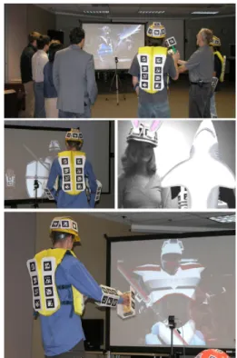
Figure 1: Users see themselves and others, some with augmented
suits or hand-held objects.
In a Magic Mirror AR system, users and onlookers can see them-selves wearing virtual suits and waving hand-held virtual objects by looking at a virtual reflection. A horizontally flipped video camera
image, merged with computer graphic content, is seen on a large screen providing the illusion of a mirror where virtual reality enters the real world. Users can appear to don medieval suits and duel with virtual swords and shields, they can become scuba divers and move move around fish and marine life, or even walk around in futuristic robotic suits.
Azuma [3] defines AR as a graphics system that combines real and virtual imagery in real time where the real and virtual objects are aligned in three dimensions and appear to share the same space. Grosjean et al [9] introduced the Magic Mirror concept, a Magic Mirror system is one modality of augmented reality where the com-monly shared space is the area in front of the virtual mirror.
The AR system needs to know the relative pose or projection matrix between the camera and real objects to align the computer graphics virtual camera. The Tinmith project [2] uses GPS and elec-tronic compass sensors to determine pose for a wearable computer for roaming outdoor AR applications such as ARQuake. Other sys-tems use active (ex. LED lighting), ultrasonic, magnetic (Polyhe-mus systems), or RF position sensors which are typically cumber-some, specialized, and found usually only in research labs. With a video see through system a digital video camera input provides the ”real” part of the output image. With computer vision, this video in-put can also be used to provide the necessary 3D tracking. Thus the video input that is usually needed anyways can be used for track-ing without needtrack-ing extra sensors, thus enabltrack-ing AR’s low cost use with commonly available hardware. Marker-based vision recog-nizes special markers placed in the environment whereas marker-less vision attempts to use natural scene objects. ARToolkit [10], the Intersense system [11], and the ARTag system [6, 1] are three examples of the former, systems using corner detectors or Lowe’s SIFT operator [12] are examples of the latter. Marker-based sys-tems currently provide more reliable and general purpose operation, especially in cases with little or no unique texture for marker-less systems to find reliable correspondences, markers are placed on ob-jects on or around which augmentations are to appear. Our system using ARTag markers mounted on hand-held and wearable objects to provide object to image correspondences for use in calculating pose.
The system created at the NRC’s IIT institute achieves the goal of a fully functioning Magic Mirror with the help of fiducial markers. Each object has a set of unique markers that are used to both recog-nize the objects and calculate a projection matrix. The contribution of this paper is not the invention of the Magic Mirror paradigm, but the successful integration of various technologies into a robust system realizing the Magic Mirror idea. Several theoretical and practical hurdles had to be crossed to create the system, this paper presents the system and several methods used to achieve operation with semi-rigid objects, realistic shadows, and correct real-virtual object occlusions.
ARTag was chosen as the fiducial marker system due to its ro-bust real time performance, vanishingly low false positive and inter-marker confusion rates, and its large library of possible inter-markers. Comparisons to other marker systems are given in [6], [8], and [7]. This paper is organized as follows; the system is described from a system view, projection matrix calculation is explored, and var-ious mechanisms are described to solve pratical problems and in-crease realism.
2 MAGICMIRRORSYSTEMDESCRIPTION
The goal was to create an AR system following the Magic Mirror paradigm that could be used in museums, science centers, and other public venues. The AR experience should be a shared one, where many onlookers can share and enjoy the experience without all re-quiring specially provisioned portable or wearable computers. The system should use minimal technology that the public has access to for reasons of maintenance, equipment cost and fragility, and theft concerns. The Magic Mirror concept fits well these requirements, a rear projection screen and single video camera can all be built into a public display with the only objects the users touch being passive and easily replaceable hand-held and wearable objects with mounted fiducial markers.
The users stand and move around in front of the screen hold-ing and wearhold-ing the marker arrays, a set of ”theme” buttons allow different augmentations to be viewed relative to the hand-held and wearable objects.
The flow of processing is as follows; for each camera image frame ARTag markers are detected and matched to a 3D array be-longing to an object, this 3D model of the markers is available a priori in the running mode. The marker corners have a 3D position, in the object coordinate system, and a 2D position within the image, each corner is an object-to-image correspondences ui
✁ vi ✁ xi ✁ yi ✁ zi ✂ . If 6 or more correspondences are found for an object (two more more markers detected) then a projection matrix is calculated by the least squares method, taking into account possible planar de-generacies. The projection matrices are calculated for all visible objects, some of which are combined for the semi-rigid and ”link-age” cases. The matrices are then used to render 3D virtual objects on top of the camera image, and the resulting composite image is then output to the projection screen.
The 3D models of the marker positions within each object was calculated offline, the models were created automoatically using a bundle adjustment technique providing a fast and efficient way to calibrate the system[5].
2.1 Calculating Projection Matrices of Array Objects
To achieve the objective of augmenting 3D virtual objects into the scene the objects must be located and their projection matrices cal-culated. When an object is detected (by its ARTag marker array), a projection matrix is calculated and used to set the OpenGL mod-elview matrix for every image frame such that a virtual content can be rendered and to appear attached to the real object.
The projection matrix can be determined from a correspondence list of marker corners in the image and in 3D object coordinates by solving for linear equations. It is not necessary, and in fact in some cases undesirable, to calculate the full euclidean pose since the final product is 2D image data. The goal is to create the illusion of co-existence and so it is better for the projection matrix to be slightly incorrect, i.e. not containing a true rotation matrix, but to fit the image as best as possible despite camera imperfections.
2.2 Detecting Degenerate Planar Cases
If all the object-to-image correspondences ui
✁ vi ✁ xi ✁ yi ✁ zi ✂ lie upon a plane, then there is not one unique (up to scale) projection matrix but a linear range of solutions. This will result in a wildly flickering augmentation due to the numerical instability. This case must be detected and corrected, in our system we calculate the projection matrix another way in this case.
There are a few ways to detect this degenerate case, the way im-plemented in our Magic Mirror system is to use plane fitting tech-niques to attempt to fit a plane to the 3D coordinates, if a plane is found that well fits the data then we know not to attempt a direct calculation of the projection matrix. In this way, for each object this planarity test is first applied to the correspondence set to
deter-mine whether to calculate the projection matrix directly or via the intermediate homography.
Figure 2: Stages of Processing. (Top left): input camera image with
detected ARTag fiducial markers, (bottom left) projection matrix cal-culated (visualized by overlaid cube), and (right) two example aug-mentations using the matrix.
Fig.2 shows a projection matrix being calculated for a simple cube object and used to render a moving fish animation.
3 AUGMENTING WITH HAND-HELD AND WEARABLE AR
-RAYS
This section describes more about the practical considerations and mechanisms designed to create a working Magic Mirror system. Hand-held and wearable objects were created that use rigid arrays of ARTag markers. Methods to allow projection matrices to be calculated for flexible and moving parts were devised and are de-scribed below.
Figure 3: Wearable arrays on the lower legs are detected and used
to calculate a projection matrix to render virtual models.
3.1 Handling Semi-Rigid Wearable Arrays
One requirement for the wearable arrays for a Magic Mirror system to be deployed in a public site such as a museum or science center is that the arrays should be easy and quick to put on and remove. De-signing and calculating pose for a wearable array for the main torso body area was more challenging than the helmet or lower limb ar-rays because the wearable array could not be completely rigid. To accommodate different body sizes and for ease and comfort when putting the suit on and off, the array around the torso has to be flex-ible. However, this poses problems when calculating the projection matrix for the array as that the 3D point positions are unknown. If the array is to deform then the relative 3D positions cannot be known a priori.
For this reason, the solution chosen was a hybrid semi-rigid array for the torso. The suit was constructed with four rigid arrays, one
for the left and right half of the front and back as shown in Fig. 4. This provided the flexibility to allow a zipper down the front for ease in taking the suit on and off, permits the back to bend when reaching the arms back, and allows the use of adjustable straps at the side to accommodate different sized people.
The challenge is then to create a stable meta array from four rigid sub-arrays with approximate but shifting relative positions. There should be no jarring shifts as the sub-arrays come in and out of vis-ibility. The resulting projection matrix need not be precise, as that the camera parameters, 3D models, and projection matrices need not be precise but just fit the image without undesirable artefacts such that augmentation is believable. The algorithm chosen was simply to calculate the projection matrices P1, P2, P3, P4 sepa-rately for the rigid sub-arrays and to linearly combine the projection matrices weighted by the number of visible markers in each array (N1,N2,N3,N4) to produce the torso projection matrix Ptas per Eqn. 1. Since the projection matrix uses homogeneous vectors for input and output, the absolute scale of the matrix is unimportant and does not need to be normalized after the linear interpolation.
Pt N1✁ P1✂ N2✁ P2✂ N3✁ P3✂ N4✁ P4 (1) After the 3D models are made of each of the sub-arrays, an im-portant step is to scale them all correctly and rotate and translate them so they have co-incident origins and axis in a representative relative pose. The act of linear interpolation of projection matrices is not mathematically correct but has low error when the sub-arrays are not displaced too much from this representative pose. This pose was chosen by approximating the average relative position of the sub-arrays when worn on an average sized person.
Typically only two of the four rigid sub-arrays are visible at a time, as the person rotates the number of markers detected de-creases on one array while the number grows for another. The re-sultant projection matrix Ptgradually moves to be most similar to the best visible array. This solution robustly solved our requirement for a flexible and easy to use wearable array for the body area that permits the use of the projection matrix calculation of rigid arrays.
Figure 4: Semi-rigid ”Meta-array” composed of four rigid arrays and
weighted linear interpolation of their projection matrices provide a wearable array for the torso that must be flexible.
3.2 LinkageMechanism for Missing Body Parts
Another practical issue with the wearable arrays is determining the transformation matrix for body sections that don’t have markers.
We found it inconvenient and cumbersome for users to wear mark-ered objects on both the upper and lower sections of each limb, it was decided to only create wearable objects to attach to the torso and lower limbs. Marker arrays were constructed for the head, lower legs, forearms, and torso but not for the upper arms and up-per legs. Since we wish to also render augmentations for these body sections the linkage mechanism was devised.
We first attempted to use the 3D coordinate transfer function from the ARTag library to transfer lower limb coordinates to the torso and construct the pose of the upper limb in the torso coordi-nate system, but found this to be unsatisfactory due to a high error in depth from the camera due to the geometry. Small image noise would the transfered point closer and away from the camera which would cause the augmented upper limb to appear to rotate randomly around an axis parallel to the camera image plane.
Better results were achieved by not magnifying error by using the noisy 3D coordinates and to instead use an image based method. The approach was to perform the calculations in image coordinates not extrapolated 3D coordinates, using operations of translating and rotating projection matrices only. The human mechanics was sim-plified to assume that the upper limbs lie on the same plane as the lower limb, can only rotate about a single axis perpendicular to this plane, and point towards a ball and socket joint in the torso. The lower limb has projection matrix Pl, Puis the projection
ma-trix of the linkage upper limb, and Pt is for the torso. An image point us✁
vs✂
is found from Ptfor the desired 3D attachment point
xs✁
ys✁
zs✂
on the torso. Puis found by first translating to the
upper-lower limb pivot point in the upper-lower limb’s coordinate system and then rotating around the lower limb’s Z-axis such the Y-axis of Pu
includes (points to) us✁
vs✂
. Therefore the upper limb is created such that it shares the same X-Y plane of the lower limb but points towards the torso. By having the upper limb only point to the torso attachment point and not stretch to meet it means that any 3D error in calculating xs✁
ys✁
zs✂
does not casuse the upper limb’s torso end to move incorrectly towards or away from the camera. As much pose information as possible was maintained from the lower limb to reduce the effect of depth error. This was found to provide a much smoother and natural augmentation at the cost of needing to align the wearable array on the lower limb more carefully.
Fig.5 demonstrates this with the ”robot suit” augmentation.
Figure 5: Linkage mechanism infers upper arm projection matrix Pu,
upper arm follows lower arm but swivels to face virtual ball and socket on torso.
4 AR GRAPHICSISSUES
There are a few issues that differentiate AR from regular computer graphics, since the virtual and real objects need to appear to belong together introducing challenges not faced when dealing with virtual imagery alone. Transparency of virtual objects to see real objects behind, using transparency to approximate lighting, and a method for creating approximately correct occlusion relationships are now discussed.
4.1 Transparency
The blending of real and virtual data for individual pixels helps to improve the realism of the AR experience. An example is shown in Fig.6.
Figure 6: Transparency example: (Left) tinted glass on the scuba
mask visor, (right) transparency used to simulate shadows of vir-tual objects onto real ones, a semi-transparent textured object is rendered on top of the table surface, note the shadow cast on the envelope.
Real and virtual objects should cast shadows on one another. An example of real objects casting shadows on virtual ones is the cloth augmentation work of Bradley [4]. Bradley used impainting to remove the black parts of ARTag and circular markers printed on cloth to capture the shadows falling on the cloth, this shadow mask was used as a filter on 2D augmentations drawn on the cloth. A simple way to create an effect of the opposite was using in the Magic Mirror project, and some related table-top AR work, using semi-transparent textures with ”baked” shadows. This requires a knowledge of the geometry of the real object, a shadow can be ren-dered onto the surface which is renren-dered with an alpha channel. The submarine model in Fig. ref shows a shadow being cast on the table and the envelope.
4.2 Generating Correct Occlusion Relationships
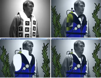
AR literature has concentrated much attention to the required pose tracking methods or applications of AR, with less emphasis on the problem of creating correct occlusion relationships. Virtual objects are typically drawn over top of the image from a video camera, the camera image is used as a background image typically rendered as a texture on a quadrilateral perpendicular to the virtual camera placed at a distance behind all the augmentations. This is fine in the ba-sic scenario prepared by AR developers where augmentations are drawn on top of a table or piece of paper, such that there would not normally be any real objects in front that would occlude the vir-tual object. However, with more complex systems such as the NRC magic mirror system there are many cases where partial or entire virtual objects are behind a real object and need to occluded by the real object to satisfy the illusion of co-existence. Simply rendering virtual content over top of real imagery produces incorrect occlu-sion relationships such as the scuba tank in the top right image of Fig. 7.
5 CONCLUSION
A Magic Mirror system where users can see real and virtual ob-jects appearing in a ”virtual reflection” provided by a digital video camera and a large display. Hand-held and wearable objects have fiducial markers mounted on them allowing objects to be identified and projection matrices calculated from the marker corner corre-spondences. Virtual objects and animations are then rendered using the projection matrices, using transparency and ”dark matter” tech-niques to achieve greater realism and to approximate correct oc-clusion relationships. The application of computer vision and AR technology was used to successfully implement a robust and enter-taining sytem for public use.
Figure 7: Usage of ”dark matter” to provide correct occlusion
rela-tionship. Upper left: input camera image. Upper right: image after augmentation is naively added on top of image. Note the incorrect occlusion relationships such as the scuba tanks drawn in front of the body. Lower left: ”dark matter” object drawn to approximate torso shape. Lower right: ”dark matter” object not rendered to image but drawn to z-buffer allowing torso region to approximate correct occlu-sion by the body.
ACKNOWLEDGEMENTS
The author wishes to acknowledge the 3D art of Brad Hetherington and programming support of Luke Burkett in the development of the magic mirror system.
REFERENCES
[1] http://www.artag.net/ (artag webpage). [2] http://www.tinmith.net/ (tinmith website).
[3] R. Azuma. A survey of augmented reality. In Presence: Teleoperators
and Virtual Environments 6, volume 4, pages 355–385, 1997.
[4] D. Bradley, G. Roth, and P. Bose. Augmented clothing. In Graphics
Interface, pages 9–10, 2005.
[5] M. Fiala. The squash 1000 tangible user interface system. In 2005
IEEE / ACM International Symposium on Mixed and Augmented Re-ality (ISMAR 2005), Vienna, Austria.
[6] M. Fiala. Artag, a fiducial marker system using digital techniques. In
CVPR’05, volume 1, pages 590 – 596, 2005.
[7] M. Fiala. Comparing artag and artoolkit plus fiducial marker systems. In Haptic Audio Visual Environments and their Applications, 2005.
IEEE International Workshop on, pages 147–152, Oct 2005.
[8] M. Fiala. Fiducial marker systems for augmented reality: Comparison between artag and artoolkit. In MIRAGE 2005, INRIA Rocquencourt, France, Mar 2005.
[9] J. GROSJEAN and S. COQUILLART. The magic mirror: A metaphor for assisting the exploration of virtual worlds. In Proceedings of 15th
Spring Conference on Computer Graphics., pages 125–129, 1999.
[10] I. P. H. Kato, M. Billinghurst. ARToolkit User Manual, Version 2.33. Human Interface Technology Lab, University of Washington, 2000. [11] L. Naimark and E. Foxlin. Circular data matrix fiducial system and
robust image processing for a wearable vision-inertial self-tracker. In
ISMAR 2002: IEEE / ACM International Symposium on Mixed and Augmented Reality, Darmstadt,Germany, Sept. 2002.
[12] I. Skrypnyk and D. Lowe. Scene modelling, recognition and tracking with invariant image features. In IEEE and ACM International
Sym-posium on Mixed and Augmented Reality (ISMAR), pages 110–119,