Assessing the Impacts of Fractionation on
Pointing-Intensive Spacecraft
by
Michael Gregory O'Neill
S.B., Aerospace Engineering, Syracuse University, 2007
Submitted to the Department of Aeronautics and Astronautics in partial fulfillment of the requirements for the degree of
SSACHUSETTS INSTFFTE OF TECHNOLOGY
MAR 2
2
2010
LIBRARIES
ARCHNES
Master of Sciencein AERONAUTICS AND ASTRONAUTICS at the
MASSACUSSETTS INSTITUTE OF TECHNOLOGY February 2010
C
2009 Massachusetts Institute of Technology. All rights reserved.The author hereby grants to MIT permission to reproduce and to distribute publicly paper and electronic copies of this thesis document in whole or in part in any medium now known or hereafter created.
Signature of Author... ...
Department of Aeronautics and Astronautics September 11, 2009
A
Certified by...- -
-Annalisa L. Weigel, Assistant Professor of Aeronavtics and Astronautics Thesis Supervisor
A ccep ted b y ... - . .---David L. Darmofal, Professor of Arautics and Astronautics
Associate Department Head, Aeronautics and Astronautics Chair, Committee on Graduate Students
Assessing the Impacts of Fractionation on
Pointing-Intensive Spacecraft
by
Michael Gregory O'Neill
Submitted to the Department of Aeronautics and Astronautics on September 11, 2009 in partial fulfillment of the requirements for the degree of Master of Science in Aeronautics and Astronautics.
Abstract
Fractionated spacecraft consist of physically independent, "free-flying" modules composed of various subsystems. Thus, a fractionated spacecraft might consist of one-module responsible for the power generation and storage, another module responsible for the communications and computing, another module responsible for the attitude and guidance determination, another module responsible for the payload, and so on. Fractionated spacecraft are of particular interest for pointing-intensive, remote sensing mission spacecraft because of their ability to physically decouple subsystems and payloads that truly need precise pointing, thereby potentially reducing the lifecycle cost of fractionated spacecraft relative to a comparable monolithic spacecraft, for a given space mission. Additionally, using fractionation to decouple pointing-intensive subsystems and payloads may potentially reduce the mass and size of the module containing the payload in a fractionated spacecraft (i.e., Payload Module) relative to that of a comparable monolithic spacecraft. If fractionated spacecraft prove to reduce the mass and size associated with the Payload Module, for a given pointing-intensive, remote sensing mission, it may enable pointing-intensive fractionated spacecraft to have longer space mission lifetimes than comparable monolithic spacecraft.
This research seeks to quantitatively assess the impacts of various fractionated spacecraft architecture strategies on the lifecycle cost, mass, propellant usage, and mission lifetime of pointing-intensive, remote sensing mission spacecraft. A dynamic lifecycle simulation and parametric model was used to assess the lifecycle cost impacts, while the mass, propellant usage, and mission lifetime impacts were assessed using a non-parametric, physics-based computer model. Results from the research demonstrate that fractionated spacecraft can be both more and less expensive than a comparable monolithic spacecraft performing the same space mission. Additionally, the results show that due to the ability of fractionated spacecraft to decouple subsystems and payloads that truly need precise pointing, the mass and propellant usage of the Payload Module can be appreciably less than that of a comparable monolithic spacecraft. Subsequently, fractionated spacecraft can attain longer mission lifetimes than a monolithic spacecraft, and in certain instances, do so with a lesser lifecycle cost than the monolith at its respective shorter mission lifetime.
Thesis Supervisor: Annalisa L. Weigel
Title: Assistant Professor of Aeronautics and Astronautics 3
Biographical Note
Greg O'Neill grew up in Lewisburg, Pennsylvania and graduated from Lewisburg Area High School in June of 2003. Thereafter he began his engineering studies at Syracuse University in the Department of Mechanical and Aerospace Engineering. In May of 2007, he graduated from Syracuse University with a Bachelors of Science in Aerospace Engineering and a minor in Mathematics and Economics. Then in September of 2007, he began his graduate studies at Massachusetts Institute of Technology. At MIT, he has a socio-technical interdisciplinary education and research focus, primarily drawing from the fields of Aerospace Engineering, Systems Engineering, Space Systems Design (Architecture), Mathematics, and Economics. He is particularly interested in the notion of value-centric design and its implications for assessing innovative spacecraft architectures. After completion of his Master's degree at MIT in September of 2009, he intends on pursuing his doctorate at MIT in an area related to his current research interests.
Following the completion of his collegiate education, Greg plans to teach abroad for two years through a nonprofit organization and then upon his return to the United States, pursue a research-intensive, professional career in industry or academia.
---Acknowledgements
The completion of a Master of Science degree at MIT was never part of the "plan" I had for my education and professional career when I began my engineering studies six years ago. In fact, my confidence level was low when I began studying engineering and I honestly never thought I would never make it past the first semester. I mention this because upon examining my educational achievements to date, it emphasizes the true significance of all those who have helped me throughout my education. Thankfully, due to the influence of these individuals, over time my educational "plan" changed radically, for the better, and I began to make the transition from an unsure engineering student to a highly motivated and successful engineering student who truly loved his education. Eventually, I knew that part of the "plan" meant attending graduate school and that this would form the necessary foundation for my continual pursuit of knowledge. It is for these reasons that I am deeply appreciative of those who have contributed to my growth as a person and as a student, ensuring that my educational dreams are continually realized. Each of these individuals has, in their own unique way, fostered my education and helped me become a more confident person and student - something I simply could not have done on my own.
I would like to offer my gratitude to a few individuals who have had a significant impact on my education and life. First, I would like to thank my academic advisor, Prof. Annalisa L. Weigel. She provided me with my first "home" at MIT and has since been supportive of all of my academic endeavors. Throughout my time at MIT, she has continually provided me with opportunities to excel in my field and has served as source of unwavering guidance and enlightenment for my education and research; and for this, I will forever be grateful.
Additionally, I would like to thank the Syracuse University College of Engineering and Mathematics, specifically, Kathleen Joyce, Dr. John Dannenhoffer III, Dr. Dan Zacharia, Dr. Barry
Davidson, Dr. Alan Levy, and Dr. Thong Dang. I credit all of these individuals as being pivotal to my development into a successful engineering student. Without their support to continually guide and push me in new and more challenging directions during my undergraduate education, I could not have become the confident and successful engineering student I am now. I cannot express the profound gratitude I have for these individuals in helping me grow beyond even my own expectations during my four years at Syracuse. As I continually achieve previously unfathomable goals in my education and life, it is my way of saying thanks to these individuals for believing in me.
Finally, I would like to extend my gratitude and love to the most important individuals in my life: family and friends; specifically, Shannon Lack, Katie Lack, Robert Lack, Isabella O'Neill, Michael Byerly, Jeremy Quant, Ryan Hollm, and Christopher North. Although I have had a rather tumultuous life, my family and friends have been supportive of all my life and academic endeavors. Without my family and friends, I could not have risen above those moments in my life when the hardships seemed insurmountable. I am deeply appreciative and loving of my family and friends for helping me become a better person and perpetually strengthening in me the notion that in life I must work hard to achieve great things, because great things... well, would not be so great without all the hard work.
7
Table of Contents
Abstract ...
3
Biographical Note...5
Acknowledgem ents...7
Table of Contents...9
List of Figures...
13
List of Tables ...
17
List of Acronym s...19
1.
Research M ethodology ...
21
1.1. Research Methodology Overview... 21
1.1.1. Phase I: Development ... 22
1.1.2. Phase II: M odeling... 23
1.1.3. Phase III: A nalysis... 23
1.1.4 . Phase IV : Synthesis ... 23
2.
Problem Form ulation ...
25
2.1. Relevant Concepts and Terminology ... 25
2.1.1. Spacecraft Performance ... 25
2.1.2. Fractionation ... 26
2.1.3. Fractionated Spacecraft ... 26
2.1.4. Spacecraft and Spacecraft Architecture ... 29
2.1.5. Shared R esources ... 30
2.1.6. Fractionated Spacecraft Technology Demonstrations... 36
2.1.7. Remote Sensing Missions and Pointing-Intensive Spacecraft ... 43
2.1.8. Lifecycle Uncertainties and Consequent Risks ... 44
2.1.9. Spacecraft Value Proposition ... 45
2.1.10. Confidence in the Value Proposition... 46
2.2. Motivation ... 50
2.2.1. Positive and Negative Hypotheses about Fractionated Spacecraft ... 50
2.2.2. Unknown Spacecraft Value Propositions... 53
2.3. Literature Review ... 54
2 .3.1. A cadem ia ... 55
2.3.2. Industry and Government... 57
2.3.3. Lim itations ... 59
2.4. Problem Statement and Research Contributions...62
2.5. Research Questions ... 63
3.
M odeling: The Spacecraft Evaluation Tool...
65
3.1. SET Overview...65
3.2. SET Inputs ... 66
3.2.1. Launch V ehicle ... 67
3.2.2. Lifecycle & D esign ... 68
3.2.3. Spacecraft Architecture... 70
3.3. Model Processes ... 72
3.3.1. Physics-Based Model... 74
3.3.2. C ost M odel ... 75
9
3.3.3. Dynamic Model... 76
3.4. SET Outputs ... 77
3.4.1. Subsystem and Component-Level SET ... 78
3.4.2. M odule-Level SET ... 79
3.4 .3. System -Level ... 80
3.5. SET Output Perspectives: System versus Payload Module...82
3.5.1. System and Payload Module Lifecycle Cost ... 83
3.5.2. Forming the Value Proposition from the SET Outputs... 84
3.6. SET Limitations and Implications for the Research Contributions ... 84
4. Analysis: SET Results... 87
4.1. Analysis (Case Study) SET Inputs ... 89
4 .1.1. Launch V ehicle ... 90
4.1.2. Lifecycle & Design ... 90
4.1.3. Spacecraft Architecture ... 93
4.2. Results Format ... 101
4.2.1. C ase Study Legends ... 10 1 4.2.2. Interpreting Lines of Data Points ... 103
4.2.3. Dynamic Lifecycle Cost Order Statistic, Five-Number Summary ... 105
4.2.4. Mission Lifetime Capability ... 105
4.3. System Mass and Propellant Usage ... 107
4.3.1. Trends in System Mass and Propellant Usage ... 108
4 .3.2 . System M ass ...
111
4.3.3. System Propellant Usage ... 112
4.4. System Dynamic Lifecycle Cost ... 115
4.5. Confidence in the System Dynamic Lifecycle Cost ... 120
4.5.1. Static versus Dynamic Lifecycle Cost ... 121
4.5.2. Statistical Confidence in the Dynamic Lifecycle Cost... 122
4.5.3. Lifecycle Cost Probability Density Functions ... 126
4.6. System and Payload Module Perspective... 128
4.7. M ission Lifetime Capability... 132
5. Synthesis: Discussion of the Results ... 137
5.1. The Value Proposition: Trends and Formation ... 137
5.1.1. Value Proposition Trends: The Costs and Benefits of Fractionation ... 137
5.1.2. Value Proposition Formation... 142
5.2. Response to the Research Questions... 143
5.2.1. Research Question 1: Spacecraft Architectures ... 144
5.2.2. Research Question 2: Payload Performance ... 147
5.2.3. Research Question 3: Lifecycle Uncertainties... 149
5.2.4. Summary of Responses to the Research Questions... 152
6.
Conclusion ...
155
6.1. Research Contributions Revisited... 155
6.1.1. Implications of achieving the Second Research Contribution... 156
6.2. Research Methodology Objectives Revisited ... 157
6.3. Reflections ... 158
6.3.1. The Spacecraft Evaluation Tool...158
6.3.2. The Value Proposition...160
10
6.3.3. The Role of Shared Resources... 161
6.3.4. Further Exploration of the Value Proposition ... 161
6.3.5. Previous Assessments of Fractionation ... 162
6.4. Is there a "Case for Fractionation"?... 163
References ...
165
Appendix A
Implementation Challenges for Fractionation... 169
Appendix B
Static and Dynamic Lifecycle Cost ...
171
Appendix C
The SET and Lifecycle Uncertainties ...
175
Appendix D
LCC Distributions and M CA Implications ...
177
Appendix E
Optimistic Perspective of Fractionated Spacecraft...181
11
List of Figures
Figure 1-1. The research methodology. ... 21
Figure 2-1. The three perspectives for classifying a spacecraft as being fractionated or monolithic. ... 27
Figure 2-2. Homogenous, heterogeneous, and mixed fractionated spacecraft. ... 28
Figure 2-3. A notional fractionated spacecraft. ... 28
Figure 2-4. Shared Resources: Comm_CS_C&DH. ... 30
Figure 2-5. Honeywell IMU and Aero/Astro miniature star tracker. ... 32
Figure 2-6. Electromagnetic conduction (short distance) and a flexible waveguide (moderate distance). . 35 Figure 2-7. Conceptual representation of a laser power beaming wireless power distribution system. .... 35
Figure 2-8. A SCAMP in its neutral buoyancy environment... 37
Figure 2-9. One of the SPHERES on the low-friction test bed at MIT. ... 38
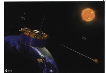
Figure 2-10. An artist's rendition of a Cluster 11 satellite orbiting the Earth... 40
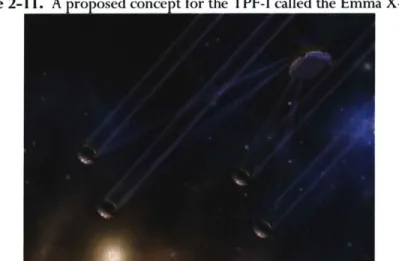
Figure 2-11. A proposed concept for the TPF-I called the Emma X-Array. ... 41
Figure 2-12. Pointing accuracy description. ... 44
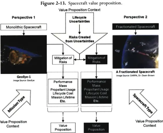
Figure 2-13. Spacecraft value proposition... 46
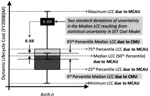
Figure 2-14. Quantifying LCC uncertainty relative to the central measure of tendency. ... 48
Figure 2-15. Representing Dynamic LCC uncertainty relative to the measure of central tendency... 49
Figure 2-16. Unknown spacecraft value propositions... 53
Figure 2-17. A fractionated spacecraft as envisioned by DARPA. ... 59
Figure 3-1. SET overview: functional flow block diagram. ... 65
Figure 3-2. Overview of SET inputs. ... 66
Figure 3-3. Overview of SET models and respective model processes. ... 72
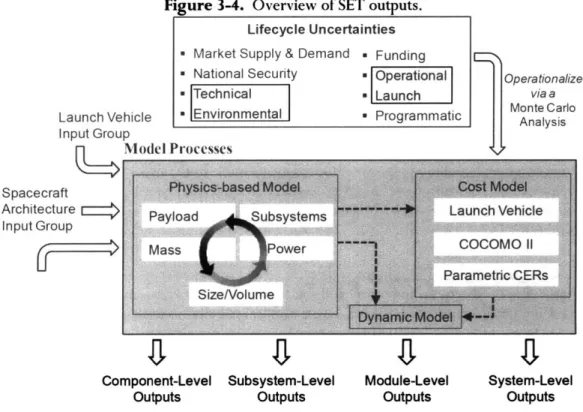
Figure 3-4. Overview of SET outputs. ... 77
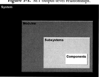
Figure 3-5. SET output-level relationships... 78
Figure 3-6. System and Payload Module perspectives. ... 82
13
Figure 4-1. Analysis outline: presentation of results. ... 88
Figure 4-2. Case Study 1, 2, and 3: one-module (monolithic) spacecraft architecture(s). ... 94
Figure 4-3. Case Study 1: two-module fractionated spacecraft architectures. ... 95
Figure 4-4. Case Study 2 and 3: two-module fractionated spacecraft architectures... 95
Figure 4-5. Case Study 1: three-module fractionated spacecraft architectures... 96
Figure 4-6. Case Study 2 and 3: three-module fractionated spacecraft architectures. ... 97
Figure 4-7. Case Study 1: four-module fractionated spacecraft architectures. ... 98
Figure 4-8. Case Study 1: condensed representation of spacecraft architectures. ... 100
Figure 4-9. Case Study 2: condensed representation of spacecraft architectures. ... 100
Figure 4-10. Case Study 3: condensed representation of spacecraft architectures... 101
Figure 4-11. Legend for Case Study 1 results. ... 102
Figure 4-12. Legend for Case Study 2 results. ... 102
Figure 4-13. Legend for Case Study 3 results. ... 103
Figure 4-14. Distinguishing inter-module separation distance for a given spacecraft architecture... 104
Figure 4-15. Distinguishing ground resolution for a given spacecraft architecture. ... 104
Figure 4-16. Distinguishing mission lifetime for a given spacecraft architecture... 104
Figure 4-17. Representing Dynamic LCC uncertainty relative to the measure of central tendency... 105
Figure 4-18. Mission lifetime extension (capability) analysis logic/reasoning... 107
Figure 4-19. Trends in System Mass and Propellant Usage. ... 108
Figure 4-20. Trends in System Mass and Propellant Usage with respect to System Dynamic LCC. ... 109
Figure 4-21. System Mass with respect to Ground Resolution (payload performance)...112
Figure 4-22. System Propellant Usage with respect to Ground Resolution (payload performance). ... 113
Figure 4-23. System Propellant Usage with respect to Dynamic LCC (Mission Lifetime and PoIM). 114 Figure 4-24. System Dynamic LCC and Mass with respect to inter-module separation distance. ... 115
Figure 4-25. System Dynamic LCC and Ground Resolution (payload performance). ... 118
Figure 4-26. System Dynamic LCC and Mass with respect to Mission Lifetime and PoIM. ... 119
Figure 4-27. Trends in System Static and Dynamic LCC with respect to separation distance ... 121
Figure 4-28. Median System Dynamic LCC confidence for select Case Study I architectures ... 123
Figure 4-29. Median System Dynamic LCC confidence for select Case Study 2 architectures. ... 124
Figure 4-30. Median System Dynamic LCC confidence for select Case Study 3 architectures ... 126
Figure 4-31. Spacecraft Architecture I (monolithic) probability density function (histogram). ... 127
Figure 4-32. Spacecraft Architecture 3 (fractionated) probability density function (histogram) ... 127
Figure 4-33. System and Payload Module perspective with respect to Mass. ... 129
Figure 4-34. System and Payload Module perspective with respect to Dynamic LCC...131
Figure 4-35. Mission Lifetime benefits due to fractionation (all Ground Resolutions). ... 133
Figure 4-36. Mission Lifetime benefits due to fractionation (0.5 m Ground Resolution) ... 134
Figure A-I. Implementation challenges for fractionated spacecraft. ... 170
Figure B-I. Cost and cumulative cost profile for a fractionated spacecraft (7-year mission lifetime). 171 Figure C-I. Notional lognormal distribution of failure times. ... 175
Figure D- 1. Notional Dynamic LCC distribution... 177
Figure D-2. Dynamic LCC distributions: monolithic spacecraft ... 178
Figure D-3. Dynamic LCC distributions: two-module fractionated spacecraft. ... 179
Figure D-4. Dynamic LCC distributions: three-module fractionated spacecraft. ... 180
Figure E- . Reading the information in Table E- I and Table E-2... 184
15
List ofTables
Table 2-1. Spacecraft lifecycle uncertainties and consequent risks. ... 45
Table 2-2. Previous assessments of fractionated spacecraft: contributions and limitations... 62
Table 3-1. SET launch vehicle database... 67
Table 3-2. SET Lifecycle & Design inputs... 69
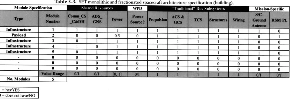
Table 3-3. SET monolithic and fractionated spacecraft architecture specification (building) ... 71
Table 3-4. Overview of SET model processes characterized in a design structure matrix. ... 73
Table 3-5. SET cost model elements... 76
Table 3-6. Subsystem and component-level SET outputs. ... 79
Table 3-7. Static and dynamic module-level SET outputs. ... 80
Table 3-8. Static, dynamic, and, Ifecycle cost statistic system-level SET outputs... 81
Table 4-1. C ase study results guide. ... 89
Table 4-2. Case Study Launch Vehicle inputs. ... 90
Table 4-3. Case Study Lifecycle & Design inputs. ... 90
Table 5-1. C ase study results guide. ... 143
Table 5-2. Research Question 1: summary of responses with regard to the value proposition. ... 146
Table 5-3. Research Question 2: summary of responses with regard to the value proposition. ... 148
Table 5-4. Research Question 3: summary of responses with regard to the value proposition. ... 151
Table 5-5. Research Questions: summary of responses with regard to the value proposition... 152
Table E-1. The most competitive fractionated spacecraft value propositions for Case Study I and 2... 182
Table E-2. The most competitive fractionated spacecraft value propositions for Case Study 2 and 3...183
17
List of Acronyms
AFRL AFOSR AC AIAA ASAT Arch as ANDE ACS ADS BoL BTS C&DH Comm CS CONOPS COCOMOII CERs CMU cdf DARPA DSM DC EoL EPS EM ESA ExEP FCal FY2008SM F6 GINA GOES GEO GCS GNS HIL IMU Infra ICE IA&T LBTI LV LCAir Force Research Laboratory Air Force Office of Scientific Research Alternating Current
American Institute of Aeronautics and Astronautics Anti-Satellite Attack
Spacecraft Architecture Arcsecond
Atmospheric Neutral Density Experiment Attitude Control System
Attitude Determination System Beginning-of-Life
Bernoulli Trial Sequence Command and Data Handling Communications
Computer System Concept of Operations
COnstructive COst MOdel: Second Edition Cost Estimating Relationships
Cost Model Uncertainty
Cumulative Distribution Function
Defense Advanced Research Projects Agency Design Structure Matrix
Direct Current End-of-Life
Electrical Power System Electromagnetic
European Space Agency
Exoplanet Exploration Program Fence Calibration
Fiscal Year 2008 United States Dollars (in millions) Future, Fast, Flexible, Fractionated, Free-Flying Generalized Information Network Analysis
Geostationary Operational Environmental Satellites Geosynchronous Orbit
Guidance Control System Guidance Navigation System Hardware-in-the-Loop Inertial Measurement Unit Infrastructure
Integrated Concurrent Engineering Integration, Assembly, and Testing Large Binocular Telescope Interferometer Launch Vehicle
Lifecycle
LCC LEO MIT MoE mas MCA MCAU MMD MATE MATE-CON MAUT NASA NOAA NRL NRE ND Ops PL PI pdf PolM RW RE RSM R&D SCAMP S/C SET SIM SK SLCC SPHERES TPF-C TPF-I TOS TCS TT&C UV USD UNP USCM8 VP V&V VPS WPD Lifecycle Cost Low Earth Orbit
Massachusetts Institute of Technology Measures of Effectiveness (MoE) Milli-arcsecond
Monte Carlo Analysis (Simulation) Monte Carlo Analysis Uncertainty Multimodal Distribution
Multiple (Multi-) Attribute Tradespace Exploration
Multiple (Multi-) Attribute Tradespace Exploration with Concurrent Design Multiple (Multi-) Attribute Utility Theory
National Aeronautics and Space Administration National Oceanic & Atmospheric Administration Naval Research Laboratory
Nonrecurring (Costs) Normal Distribution Operations
Payload
Pointing-Intensive
Probability Density Function Probability of Infant Mortality Reaction Wheel
Recurring (Costs) Remote Sensing Mission Research and Development
Secondary Camera and Maneuvering Platform Spacecraft
Spacecraft Evaluation Tool (SET) Space Interferometer Mission Stationkeeping
Stochastic Lifecycle Cost
Synchronize Position Hold Engage & Reorient Experimental Satellites Terrestrial Planet Finder - Coronagraph
Terrestrial Planet Finder - Interferometer Terrestrial Observer Swarm
Thermal Control System
Tracking, Telemetry, and Control Ultraviolet
United States Dollars
University Nanosatellite Program
Unmanned Space Vehicle Cost Model, 8"' Edition Value Proposition
Verification & Validation Visual Positioning System Wireless Power Distribution
1. Research Methodology
The research methodology serves as the foundation for the development and progression of this research. Subsequently, there were objectives set forth specifically regarding the research methodology, which ensured that each stage of the research development and progression was a demonstration of scholarly achievement. The four the research methodology objectives are:
The research methodology must...
I. Formulate comprehensive, appropriate, and quantitative responses to the research questions (see Section 2.5).
2. Engender the unique contributions of this research (see Section 2.4). 3. Produce meaningful results reliably and repeatedly.
4. Be readily extendable to demonstrate broad applicability of the methodology to problems (i.e., questions) that were beyond the original scope of this research.
1.1.
Research Methodology Overview
A conceptual overview of the research methodology is given in Figure 1-1. The research methodology was developed in January of 2008 and the subsequent execution of all research methodology constituents (shown as blocks in Figure
1-1)
was completed by August of 2009. There are four phases of the research methodology, broadly categorized as development, modeling, analysis, and synthesis. Each of these phases has several constituents, where each constituent prescribes specific tasks to be completed that further mature the research. The dates assigned to each phase of the research methodology represent the time period in which the majority of the efforts put forth to address that phase took place; however, recognize that many aspects of this research were conducted concurrently.Figure 1-1. The research methodology.
Development
Modeling
Analysis
Synthesis
(Chapter 2) (Chapter 3) (Chapter 4) (Chapter 5)
Jan.'08'- Jan.'09 Feb. - July'09 June -Aug.'09 June -Aug. '09
FaCtIOnated T
Problem
Sparaft-Hypoiso
__
Statementand
.
vtuaionl
and MotivaOn
ReacMhTool
T)
Queslons
Deeopt,
modofnatedGeran
S.ET Results
DARPA F6 Program: Phase I
21
Conveniently, each of the four phases of the research methodology is the focus of one chapter.
" Phase I: Development - Chapter 2
* Phase II: Modeling - Chapter 3
* Phase III: Analysis - Chapter 4
* Phase IV: Synthesis - Chapter 5
1.1.1. Phase I: Development
The efforts put forth in addressing and developing the constituents of Phase I: Development, took place from January 2008 to January 2009. Chapter 2 discusses the outcomes from Phase I. The primary objectives of Phase I were to provide a foundation for understanding fractionated spacecraft as well as identify areas in which knowledge can be meaningfully contributed with regard to understanding the value propositions of fractionated spacecraft. As such, the first constituent of Phase I was the Fractionated Technology and Concept investigation (see Section 2.1). In this constituent, investigations of key concepts and technology related to fractionated spacecraft as well as demonstrations of fractionated spacecraft/technology were conducted. The second constituent of Phase I was the Hypotheses and Motivation development (see Section 2.2). In this constituent, important positive and negative hypotheses about fractionated spacecraft were researched and documented to serve as a source of motivation for the research. The third constituent of Phase I was performing a Fractionated Assessment Literature Review (see Section 2.3). The objective of this constituent was to gain an understanding of previous assessments of fractionated spacecraft. And the fourth and last constituent of Phase I was the formulation of the Problem Statement and Research Questions (see Sections 2.4 and 2.5). In this constituent, the synthesis of the other three constituents in Phase I were used to develop a problem statement and research questions; these being necessary for the modeling phase, that is, Phase II of the research methodology.
The execution of constituents in Phase I of the research methodology was done concurrently with working on Phase I of the DARPA System F6 Program (see Section 2.3.2). In Phase I of the F6 program, the author was part of the Northrop Grumman Space Technology Group and had the responsibility of performing value-centric assessments of monolithic and fractionated spacecraft. This responsibility specifically involved modeling monolithic and fractionated spacecraft and quantitatively assessing their costs and benefits relative to comparable monolithic spacecraft.
22
1.1.2. Phase II: Modeling
The majority of the efforts put forth in addressing and developing the constituents of Phase II: Modeling, took place from February 2009 to July 2009. Chapter 3 discusses the outcomes from Phase II. The primary objective of Phase II was to develop a computer-based tool for assessing monolithic and fractionated spacecraft value propositions. Subsequently, the first constituent of Phase II was the Spacecraft Evaluation Tool (SET) development (see Chapter 3). The SET is a Microsoft Excel® and Matlab@ integrated software program that takes a set of inputs characterizing a particular problem (or research question) pertaining to a monolithic or fractionated spacecraft, and via a simulation, generates a set of outputs (i.e., metrics to form the value proposition). Concurrently with the SET development, the second and third constituents of Phase II were performed: SET Verification and Validation and Generating SET Results. SET Verification and Validation (V&V) provided a means for ensuring appropriateness and accuracy of the SET relative to its respective inputs and outputs. Additionally, SET V&V occurred while generating the SET results and subsequently analyzing them while conducting Phase III of the research methodology, Analysis.
1.1.3. Phase III: Analysis
The majority of the efforts put forth in addressing and developing the constituents of Phase III: Analysis, took place from June 2009 to August 2009. Chapter 4 discusses the outcomes from Phase III. Through Phase III, the SET was applied to formulate quantitative monolithic and fractionated spacecraft value propositions. Based on the value propositions generated from the SET, Sensitivity Analyses and an Analysis of Results could commence (see Section 4.3 through 4.7), which are the two constituents of Phase III. The sensitivity analyses enabled further V&V of the SET as well as an understanding of the SET inputs of interest (e.g., RSM payload ground resolution) on the SET outputs of interest (e.g., lifecycle cost). Through the Analysis of Results constituent of Phase III, monolithic and fractionated spacecraft value propositions were quantified and used to formulate responses to the research questions. Subsequently, combining (synthesizing) all of these responses was the focus of Phase IV of the research methodology, Synthesis.
1.1.4. Phase IV: Synthesis
The majority of the efforts put forth in addressing and developing the constituents of Phase IV: Synthesis, took place from June 2009 to August 2009. Chapter 5 discusses the outcomes from Phase IV. The first constituent of Phase IV was Addressing the Research Questions (see Section 5.2), which involved synthesizing the large number of responses to the research questions generated from Phase III. Then following the formulation of succinct responses to the research questions, the second constituent of Phase IV: Write Thesis, commenced. The objective of this constituent of Phase IV was to document all outcomes of the research methodology phases and their respective constituents.
23
2. Problem Formulation
A research investigation into the impacts of fractionation on pointing-intensive spacecraft necessitates an understanding of the fundamental problem, which provides both context and motivation for the investigation. The problem is formulated along five successive dimensions: (1) relevant concepts and terminology, (2) motivation, (3) literature review, (4) problem statement and research contributions, and (5) research questions. The synthesis of these five successive dimensions ensures completeness of the problem formulation and subsequently embodies Phase I of the research methodology (see Section 1. 1. 1).
2.1.
Relevant Concepts and Terminology
The first step in formulating the problem is to define and explore concepts and terminology that are essential to an understanding of this research investigation.
2.1.1. Spacecraft Performance
The performance of a spacecraft can be defined as an action (or lack thereof) that the spacecraft executes in the context of its mission that, in turn, provides value (or lack thereof) to at least one of the spacecraft's respective beneficiaries and/or beneficiary stakeholders. With regard to understanding the performance and value proposition of spacecraft, there are a few terms worth noting.
* Benefit: a service provided to an entity that is perceived as being advantageous or good. * Value: benefit at cost, that is, benefit normalized by the cost of obtaining the benefit.
* Beneficiary: an individual, group of individuals, or organization that does not expend resources
(e.g., time, money, and regulations) for the development and/or operation of a system (e.g.,
spacecraft), but does benefit from the system development and/or operation.
* Stakeholder: an individual, group of individuals, or organization that expends resources for the development and/or operation of a system, but does not benefit from the system development and/or operation.
* Beneficiary Stakeholder: an individual, group of individuals, or organization that expends resources for the development and/or operation of a system and does benefit from the system development and/or operation.
Performance can be thought of in both a static and dynamic (time dependent) sense. In a static context, performance is characterized by the instantaneous development and delivery of benefit/value, whereas in a dynamic context, performance is characterized by the accumulated development and delivery of benefit/value over a period of time. Common notions of a spacecraft performance include payload performance (e.g., ground resolution) and mission lifetime. In terms of static performance, payload performance may be quantified as instantaneous ground resolution. Alternatively, in terms of dynamic performance, payload performance may be quantified as the average payload performance over the mission (this is particularly relevant for Earth observation spacecraft having highly elliptical orbits). However, in contrast to static and dynamic payload performance, mission lifetime (performance) is only a dynamic performance metric as it necessarily quantifies time. It should be noted that the term performance can also extend beyond traditional notions of performance, such as payload performance and mission lifetime, and used to describe specific subsystem functionality characteristics of spacecraft, for example, spacecraft use of shared resources (see Section 2.1.5).
25
Often spacecraft are compared on the basis of their performance and in the case when two or more spacecraft have an identical performance, it can be stated that they are comparable. If two or more spacecraft are comparable, this enables comparisons between the spacecraft to be made on an "equal" basis per their identical performance. Comparability is particularly important when assessing a large number of candidate spacecraft architectures to determine which is, for example, the least expensive in terms of lifecycle cost for a given level of performance.
2.1.2. Fractionation
Fractionation describes a system composed of physically independent (i.e., structurally separate) constituents that can, but do not have to, collaborate to provide benefit/value to the beneficiaries and beneficiary stakeholders of that respective system. This definition for fractionation is based on a system's respective physical characteristics and functional relationships.
In literature, the terms modular and distributed often have the same connotation as fractionated as it is defined and employed hereafter. For the purposes of this research, distributed and fractionated are taken to have the same meaning, however, both of these terms differ from the term modular. A fractionated (or distributed) system has constituents are physically independent (i.e., structurally separated) and that may or may not collaborate. A modular system has constituents that, in some capacity, can be designed, manufactured, integrated, tested, and/or assembled independently of one another (e.g., concurrently) (Baldwin & Clark, 1997; Esper, 2005; Esper et al., 2004). A modular system therefore does not necessarily require that the system under consideration be fractionated (i.e., have physically independent constituents), as many systems that are monolithic in nature can be modular as well (e.g., laptop computers). However, it is worth acknowledging that fractionated systems are often perceived as being modular in nature. If a system is deemed to not be fractionated, thereby meaning that the system constituents are physically dependent (i.e., a direct or indirect structural connection can be found between all constituents), the system is considered to be monolithic.
2.1.3. Fractionated Spacecraft
Designating a spacecraft as being fractionated or monolithic first requires a definition of the system under consideration so the constituents of the system can be identified. After the system is properly defined, the system's constituents can be examined to determine if the spacecraft is fractionated or monolithic based on the definition for fractionated systems provided in Section 2.1.2.
Due to the ambiguous nature of the term "system" and "constituent", this research suggests the adoption of three perspectives that provide a logical means for designating a spacecraft as being fractionated or monolithic based on its respective constituents. For a given spacecraft, each of the three perspectives prescribes a unique meaning as to the system and its respective constituents - which, as previously stated, are fundamental to determining whether the spacecraft is fractionated or monolithic. The first perspective is the "Constellation Level" perspective; here, the system is a spacecraft constellation and the constituents are each structurally connected grouping of subsystems in the constellation (aka satellites or modules). (The term module will be employed hereafter in place of the term satellite.) The second perspective is the "Module Level" perspective; here, the system is a single module in the constellation and the constituents are the individual subsystems present in that module. And the third perspective is the "Subsystem Level" perspective; here, the system is a given subsystem of a module and the constituents are the individual hardware components within that subsystem. Figure 2-1 notionally depicts these three perspectives.
26
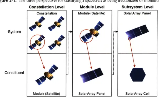
Figure 2-1. The three perspectives for classifying a spacecraft as being fractionated or monolithic.
Constellation Level
Module Level
Subsystem Level
Constellation Module (Satellite) SolarArray Panel
System
Constituent
Module (Satellite) SolarArray Panel Solar Array Cell
In Figure 2-1, if the Constellation Level perspective is considered, then the system is the constellation and the four constituents are each respective module (satellite) in the constellation. If the Module Level perspective is considered, then the system is a single module in the constellation, and the module subsystems are the constituents (in Figure 2-1 a solar array is a representative constituent). And if the Subsystem Level perspective is considered, then the system is a subsystem in a module and the constituents are the components of the subsystem (in Figure 2-1 a solar array cell is a representative constituent).
Given the definition for fractionated and monolithic spacecraft (i.e., systems) provided in Section 2.1.2, the logic for determining whether a spacecraft is fractionated or monolithic is as follows:
* If a spacecraft is deemed to be fractionated with regard to any one of the three perspectives, then it should be designated afractionated spacecraft.
* If a spacecraft is not deemed to be fractionated with regard to any one of the three perspectives, then it should be designated a monolithic spacecraft.
Following the examination of a spacecraft with respect to each of the three perspectives, if the spacecraft is deemed to be fractionated, then it will belong to one of three classes of these respective spacecraft: homogeneous, heterogeneous, and mixed (i.e., homogeneous & heterogeneous) (C. Mathieu & Weigel, 2005). Mixed fractionation is actually a subset of heterogeneous fractionation, however, there is value added in distinguishing between mixed and heterogeneous fractionation, as the term heterogeneous fails to convey strong traces homogeneity in a system. Classifying a fractionated spacecraft, from any one of the three perspectives (i.e., Constellation, Module, Subsystem Level), is done as follows:
I. A fractionated spacecraft is homogeneous if all of the respective constituents of the system are identical in both form and function.
2. A fractionated spacecraft is heterogeneous if not all of the respective constituents of the system are identical in form and/or function.
3. A fractionated spacecraft is mixed if, in the system, there are distinguishable groupings of constituents that are homogeneous and heterogeneous.
27
C 2009 Massachusetts Institute of Technology. All rights reserved.
Figure 2-2 provides instantiations of the three potential classifications of fractionated spacecraft from the Constellation Level perspective. In Figure 2-2, the system is the combination (i.e., constellation) of all four modules where each module is considered a constituent that may be identical or different from the other constituents based on its respective shape, size, and color as shown in Figure 2-2.
Figure 2-2. Homogenous, heterogeneous, and mixed fractionated spacecraft.
Homogeneous
Heterogeneous
Mixed
Typ4e
Type 1
Type 2 Type 2
In Figure 2-2, a homogenous fractionated spacecraft contains four identical modules (satellites), whereas a heterogeneous fractionated spacecraft contains four different modules. Conversely, a mixed fractionated spacecraft contains two clear groupings of identical modules but that are subsequently different from one another. In the case of Figure 2-2, if the heterogeneous and mixed fractionated spacecraft were to both classified as heterogeneous, given that mixed fractionation is a subset of heterogeneous fractionation, constructive nuances between these two fractionated spacecraft would be lost.
To serve as an illustrative example in determining whether or not a spacecraft is fractionated from each of the three perspectives, and if so, which respective class of fractionation the spacecraft belongs to, consider the spacecraft represented in Figure 2-3.
Figure 2-3. A notional fractionated spacecraft.
S1 5 S3 54 S5 S6 53 S4 5'
LI~Z~
S3LI~I1
SubsystemC 2009 Massachusetts Institute of Technology. All rights reserved.
Type I Type I
Type 1 Type 1
Type I Type 2
Type 3 Type 4
The spacecraft shown in Figure 2-3 can be examined from each of the three perspectives to determine if it is fractionated and if so what respective class of spacecraft to which it belongs.
* Constellation Level: the system is the combination of all three modules in the constellation where each respective module is considered a constituent. The system is fractionated and heterogeneous. This is evident in that all the constituents are physically independent (i.e., fractionated) but each module is different in form and functionality (i.e., heterogeneous).
e Module Level: the system is any one of' the three modules and the constituents are each of the respective subsystems in a given module. The system is not fractionated and is thereby monolithic. This is evident since each constituent is located inside the same structure/module (i.e., physically dependent).
* Subsystem Level: the system is a given subsystem in one of the modules and the constituents (not shown in Figure 1-3) are the respective components of that subsystem. The system is not fractionated and is thereby monolithic. This is evident since each constituent is located inside the same subsystem (i.e., physically dependent).
Based on this working example in determining whether the spacecraft in Figure 2-3 is fractionated or monolithic, since, from the Constellation Level perspective, the spacecraft in Figure 2-3 is deemed to be heterogeneous fractionated, the spacecraft should be designated as fractionated. Recall that it is only necessary to deem a spacecraft as begin fractionated from a minimum of one of the three perspectives for it to be considered a fractionated spacecraft.
Understandably, it may appear superfluous to examine a given spacecraft from the Constellation, Module, and Subsystem Level perspectives to determine whether the spacecraft is fractionated or monolithic. However, without the structured approach prescribed by these three perspectives (or for that matter any structured approach), there can be no consistency in the interpretation and subsequent assignment of the term fractionation (or lack thereof) to a given spacecraft. Therefore, adopting these perspectives offers one instantiation of maintaining a consistent definition of fractionated and monolithic spacecraft.
This research will investigate spacecraft that are perceived as being fractionated either the Constellation Level and/or Module Level. Additionally, from each of these two perspectives, fractionated spacecraft belonging to the homogeneous, heterogeneous, and mixed (i.e., homogeneous & heterogeneous) classes of spacecraft will be investigated.
2.1.4. Spacecraft and Spacecraft Architecture
In the discussion of this research, specifically its respective outcomes in Chapter 4, the terminology spacecraft architecture are employed instead of the term spacecraft; for example, fractionated spacecraft architecture instead of fractionated spacecraft. It should be noted that the terminology spacecraft architecture are purposely used in discussions in which the intent is to emphasize the specific design (i.e., structural hardware and subsystem composition) of spacecraft, as this is not as readily conveyed with the term spacecraft.
29
2.1.5. Shared Resources
With regard to the Constellation Level perspective (see Section 2.1.3), fractionated spacecraft consist of physically independent, free-flying modules, each of which is composed of various "traditional" spacecraft subsystems. Therefore, an essential attribute of fractionated spacecraft is their ability to physically decouple (i.e., separate) subsystems and payloads by placing them on different modules and, in doing so, enable the sharing of subsystem resources amongst modules via collaboration (e.g., power, communications, data processing, attitude and guidance determination) (Brown & Eremenko, 2006a)'. Through the dispersion and subsequent sharing of certain subsystem resources, there is associated hardware required on the modules that provide shared resources (aka sources) as well as those modules that rely on/receive shared resources (aka recipients). The hardware associated with each shared resource may be simple instantiations of current technology, as is in the case when sharing the communications subsystem, or can require the application and demonstration of new(er) technologies, as is the case in sharing the power (generation and storage) subsystem.
It is hypothesized that the ability of fractionated spacecraft to share resources will specifically cause a reduction in their respective lifecycle cost to that of a comparable monolithic spacecraft, something of great value to spacecraft beneficiary stakeholders. This thereby provides motivation for this research and its assessment of the implications of sharing resources amongst modules in fractionated spacecraft on their respective value propositions (See Section 2.1.9). The shared resources specifically investigated through this research and subsequently enumerated hereafter are representative of potential subsystem resources that can be shared in fractionated spacecraft, given present spacecraft subsystem technology(ies).
* Communications, Computer System, and Command & Data Handling (CommCSC&DH)
The Comm, CS, and C&DH subsystems can be shared amongst modules in a fractionated spacecraft (Brown & Eremenko, 2006a). Figure 2-4 provides a conceptual instantiation of sharing these three subsystem resources amongst modules in a fractionated spacecraft (a comparable monolith to the fractionated spacecraft is shown in the left of Figure 2-4).
Figure 2-4. Shared Resources: CommCSC&DH.
Module 1 Module 2 Subsystem SIC-to-Ground S3 S4 Directional Antenna - : S1 S3 S5 S4 S5 Omni-antenna or Directional antenna Module 3
'It should be noted that not all spacecraft subsystems are "fractionatable" (i.e., they cannot be shared). Some subsystems, such as the thermal control system, must be present in all the respective modules of a fractionated spacecraft.
30
For a given fractionated spacecraft, in sharing the communications (Comm) subsystem resource, it is still necessary to have at least one module with a dedicated spacecraft-to-ground (S/C-ground) antenna for the uplink and downlink of mission and housekeeping data. However, it may not be necessary to have a S/C-ground antenna on every module, as this creates unwanted redundancy. Instead, as is depicted in Figure 2-4, omni- or small directional antennas can be used for inter-module communications to route data to and from all modules in the fractionated spacecraft. Then ultimately, any data needing to be sent to the ground can be routed to Module 1, since it has the dedicated S/C-ground antenna. Analogously, all of the data coming from the ground is sent to Module I and subsequently distributed by Module 1 to all other modules via omni- (or small directional) antennas. In sharing the Comm subsystem resource in this manner, a reduction in Comm redundancy is achieved, and this has the effect of reducing the Comm subsystem requirements for the modules without a dedicated S/C-ground antenna (i.e., recipients).
Implicit to the fractionated spacecraft shown in Figure 2-4 is a shared computer system (CS) and command & data handling (C&DH) subsystem. The CS and C&DH can readily be shared amongst the modules in a fractionated spacecraft by having a non-uniform distribution of computing capabilities amongst the modules in a fractionated spacecraft. For example, the fractionated spacecraft in Figure 2-4 could have a high-performance computer system on Module 3 to process the payload (mission) data before it is transmitted to the ground via Module 1. Whereas, Modules 1 and 2 , due to the lack of a need to process payload data, can have much smaller, lower performance computer systems capable of only processing housekeeping, C&DH, and TT&C related data/tasks. As another example of sharing the CS and C&DH resource for the fractionated spacecraft shown in Figure 2-4, the computer onboard Module 3 could process the payload data as well as the housekeeping, C&DH, and/or TT&C data/tasks (in some capacity) for both Modules I and 2. This thereby further reducing the respective computing requirements and thus hardware for the CS and C&DH subsystems on Module I and 2. In sharing the CS and C&DH subsystem resources in this manner, a reduction in CS and C&DH redundancy is achieved that subsequently reduces the CS and C&DH subsystem requirements for those modules receiving the shared resource (i.e., Comm_CS_C&DH recipients).
Sharing the Comm, CS, and C&DH subsystems (referred to hereafter as the CommCSC&DH shared resource) relies on existing, and in most cases, well vetted technology (e.g., omni- and directional antennas). Therefore, the hardware associated with this shared resource, for both the sources and recipients of this shared resource, is relatively mature with respect to the technical hardware involved. However, there are still notable challenges to be addressed in employing this shared resource amongst modules in a fractionated spacecraft, which include techniques, methods, algorithms, and protocols for successfully managing (1) data delivery, (2) command and data handling, (3) housekeeping and mission data processing, and (4) tasking, scheduling, and control.
e Attitude Determination System and Guidance Navigation System (ADSGNS)
The ADS and GNS can be shared amongst the respective modules in a fractionated spacecraft. Relative to a specific frame of reference (e.g., Earth or spacecraft inertial frame of reference), the ADS and GNS is responsible for determining the rotational and translational position/orientation of a body (e.g., spacecraft, module) respectively. Similar to sharing the Comm_CS_C&DH resource, in sharing the ADS and GNS resource, reductions in redundancy amongst the modules is achieved, subsequently reducing the ADS and GNS related requirements for modules receiving the shared resource (i.e., ADS_GNS recipients).
31
If the ADS and GNS are not shared, each module in a fractionated spacecraft must have dedicated hardware that can fulfill the ADS and GNS functional responsibilities. A representative set of this dedicated hardware is an Inertial Measurement Unit (IMU) and star tracker, which together, can fully determine the rotational and translational position of each spacecraft/module that they are present on (see Figure 2-5).
Figure 2-5. Honeywell IMU and Aero/Astro miniature star tracker.
Honeywell HG9900 IMU
Aero/Astro Miniature Star Tracker
However, in contrast, if sharing the ADS and GNS resource, a visual positioning system (VPS) can be used in place of a star tracker on recipient modules of this shared resource. The work of others has suggested a VPS to be a viable option for use in place of a dedicated GNS for determining an object's translational position (Mandy, Sakamoto, Saenz-Otero, & Miller, 2007; McGhan, Besser, Sanner, & Atkins, 2006). A VPS consists of a set of sensors that can be used to detect relative translational motion/positioning between two or more bodies, each of which has a VPS/sensors. Therefore, if the ADS and GNS are shared amongst modules in a fractionated spacecraft, often one-module is selected to be the "central" module that necessarily requires an IMU, star tracker, and visual positioning system (VPS). And the remaining modules in the fractionated spacecraft, which are recipients of the ADS and GNS shared resource, thereby only, require a VPS and IMU (the IMU is still required for determining rotational orientation). Given that the "central" module in a fractionated spacecraft can determine its absolute position with respect to a given frame of reference, the other modules can determine their respective relative position to the central module, via their respective VPS's, and subsequently their absolute positions with respect to the central modules' frame of reference. In sharing the ADS and GNS resource amongst modules in a fractionated spacecraft, it reduces the ADS and GNS related requirements for those modules relying on/receiving the shared resource (i.e., ADSGNS recipients).
There are two key decisions to be made with regard to the ADS and GNS. First, whether the modules in a fractionated spacecraft need to be in a cluster or formation flying on-orbit configuration. And second, how the ADS and GNS are to maintain that on-orbit configuration (i.e., should the ADS and GNS resources be shared or should a dedicated ADS and GNS be on every module). Cluster flying describes the situation in which the relative positioning of the modules in a fractionated spacecraft is "approximate", thereby making it only necessary for each module to maintain roughly a certain relative position with respect to the other modules. And formation flying describes the situation in which the relative positioning of the modules is "exact" (i.e., within an appreciably small margin), thereby making it necessary for each module maintain a precise relative position with respect to the other modules; this subsequently presents a much more difficult relative navigation problem than does cluster flying.
32
Regardless of whether the ADS and GNS subsystems are shared, the relative navigation of structures in space (e.g., modules in a fractionated spacecraft) is an area of technology development that, in recent years, has gained appreciable momentum (Wu, Cao, & Xue, 2006). In relation to fractionated spacecraft, relative navigation is the process of keeping each of the respective modules in a fractionated spacecraft at a specific rotational orientation and translational position relative to the Earth and other modules, per the desired on-orbit configuration (i.e., cluster flying or formation flying configuration). To achieve this, relative navigation requires determining the relative state variables (i.e., position, velocity, acceleration) of a given module in fractionated spacecraft with respect to the other modules and Earth. For a given module, and based on the ADS and GNS hardware discussed herein, relative navigation relies on the use of two components. These components are (1) an IMU and VPS (if ADS and GNS are shared), or an IMU and star tracker (if ADS and GNS are not shared); and (2) relative navigation control algorithms which compute state variables based on IMU and VPS/star tracker information. Relative navigation is not a trivial challenge, especially in the case in which the inter-module separation distances are in the range of tens of meters, which is a candidate inter-module separation distance for fractionated spacecraft.
Relative navigation is an extremely complex problem given the nature of objects in space being highly susceptible to changes in rotational and translational position from interactions with the surrounding environment (e.g., solar pressure, magnetic fields). Leading research and development efforts for relative navigation systems and control algorithms is being conducted at the Massachusetts Institute of Technology (MIT) and the University of Maryland. These two universities are currently developing autonomous relative navigation systems, which achieve relative navigation with limited input from the ground (system operator). At MIT, autonomous relative navigation systems are being developed as part of the Synchronize Position Hold Engage & Reorient Experimental Satellites (SPHERES) program (Mandy, Sakamoto, Saenz-Otero, & Miller, 2007), and at the University of Maryland, autonomous relative navigation systems are being developed as part of the Secondary Camera and Maneuvering Platform (SCAMP) program (Mandy et al., 2007; McGhan et al., 2006). In addition to work done in academics, the feasibility of (autonomous) relative navigation has been, in differing capacities, demonstrated through several spacecraft/programs including Space Technology 5, Cluster II, Atmospheric Neutral Density Experiment (ANDE), and the University Nanosatellite Program.
From a hardware perspective, sharing the ADS and GNS subsystem resource (referred to hereafter as the ADS_GNS shared resource) is fairly mature owing to the fact that much the hardware associated with this shared resource has been proven in space, or is a relatively simple extension of existing technologies that are space qualified. However, there are still challenges to be addressed in employing this shared resource in a fractionated spacecraft, which include developing relative navigation control algorithms and protocols for maintaining on-orbit spacecraft/module configurations to within very small tolerances, while avoiding catastrophic on-orbit collision(s).
* Power (Power)
The Power subsystem consists of two main elements: power generation and power storage (power regulation and control is assumed implicit). It is possible to share both of these elements of the Power subsystem amongst modules in a fractionated spacecraft. In the case of sharing power generation, a module in a fractionated spacecraft can produce its own power, but additionally, some amount (or all) of the power required by one or more other modules in the fractionated spacecraft. Subsequently, these modules can each now produce less (or none of the) power than they require, thereby reducing their respective power generation requirements. Similarly in sharing power storage, a module can store power for itself, but
33