The Biomechanical Response of the Interosseous
Membrane of the Human Forearm-- An In-vitro
Investigation Using Robotics Technology
By
Louis E. DeFrate
B.S. Engineering, University of Pittsburgh, 1999
Submitted to the Department of Mechanical Engineering In Partial Fulfillment of the Requirements for the degree of
Master of Science in Mechanical Engineering
at theF TECHNOLOGY
Massachusetts Institute of Technology
JUL1620
February 2001
JU---@ Louis E. DeFrate. All Rights Reserved LIBRARIES
The Author hereby grants to MIT permission to reproduce and to distribute BARKER
publicly paper and electronic copies of this thesis document in whole or in part. A u th o r... .. ....
Department of Mechanical Engineering January 19, 2001
C ertified by ... . ..
Guoan Li Lecturer, Dep m nt of Mechanical Engineering, MIT Assistant Professor o Orhopedic Surgery/Bioengineering
Iarvard Medical School Thesis Supervisor
C ertified by... ...
Derek Rowell Professor of Mechanical Engineering
. --- Thesis Supervisor A cce pted by ... . ...
Ain A. Sonin
The Biomechanical Response of the Interosseous
Membrane of the Human Forearm-- An In-vitro
Investigation Using Robotics Technology
By
Louis E. DeFrate
Submitted to the Department of Mechanical Engineering In Partial Fulfillment of the Requirements for the degree of
Master of Science in Mechanical Engineering
Abstract
The biomechanical role of the interosseous ligament (also referred to as the interosseous membrane in the literature) of the forearm was studied using a robotics based joint testing system developed in our laboratory. This system was further modified to facilitate the biomechanical testing of forearms, which are composed of two joints (wrist and elbow) and three bones (radius, ulna, and humerus). The forearm was tested from full extension to 900 of elbow flexion and in three forearm rotations: pronation, neutral, and supination. A 100 N axial compressive load was applied to the distal radius and the in situ force in the interossous ligament was measured. The largest force in the interosseous ligament was found in supination at all flexion angles. The force in the
interosseous ligament represented up to 43% of the applied load. These results reflect the importance of the interosseous ligament in the intact forearm as well as having important clinical implications for the development of surgical
techniques in the treatment of interosseous ligament injury.
Thesis Supervisor: Guoan Li
Title: Lecturer, Department of Mechanical Engineering, MIT Assistant Professor of Orthopedic Surgery/Bioengineering,
Harvard Medical School Thesis Supervisor: Derek Rowell
Acknowledgements
First of all, I'd like to thank my advisors, Dr. Li and Dr. Rowell, for their guidance and support throughout this project. The clinical perspectives offered
by Dr. James H. Herndon, Chairman of Orthopedic Surgery at Harvard Medical
School, were extremely valuable to this project as well. I'd also like to thank the
other members of our research team for their assistance, input, and their great personalities. Thanks, Ephi Most, Jeremy Suggs, Shay Zayontz, and Vaida Glatt! I'd also like to thank all the great people at the OBL for their input and support. The financial contribution from the Whitaker Foundation and the A 0 Foundation were greatly appreciated. Finally, I'd like to thank my family and wonderful wife Marisa for their loving encouragement.
Table of Contents
Abstract ... 2
Chapter 1: Introduction ... 5
1.1 Functional Anatomy of the Forearm ... 5
1.2 Clinical Relevance ... 6
1.3 Biomechanical Studies of the IOL... 7
1.4 Objective ... 10
Chapter 2: M ethods ... 11
2.1 Experim ental Setup ... 11
2.2 Specim en Preparation ... 12
2.3 Coordinate Systems for Human Forearm System ... 13
2.4 Equilibrium Position of Forearm Under External Loads ... 18
2.5 Passive Path ... 22
2.6 Displacement of Radius and Force in IOL Under Compressive Loads... 24
2.7 System Validation ... 25
Chapter 3: Results... 28
3.1 System Validation ... 28
3.2 Displacem ent of Radius ... 29
3.3 Force in the IO L ... 32
3.4 Analysis of left versus right forearms ... 35
Chapter 4: Discussion... 40
Chapter 5: Conclusion and Future W ork... 45
5.1 Conclusion ... 46 5.2 Future W ork ... 47 References ... 48 Appendix A ... 50 Appendix B ... 55 Appendix C ... 67
Chapter 1: Introduction
1.1 Functional Anatomy of the Forearm
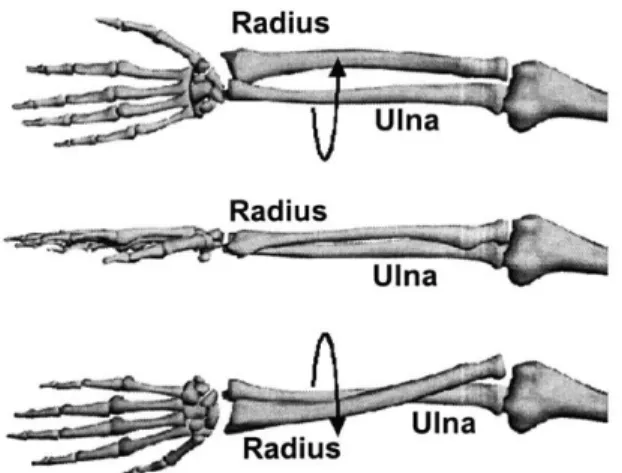
The human forearm consists of two bones, the radius and the ulna. These two bones articulate with each other and the distal humerus at the elbow and with the carpal bones at the wrist. Flexion of the elbow joint and the rotation of the forearm (Figure 1) allow for the positioning of the hand in space. For example, drinking a cup of coffee requires flexion range of motion at the elbow, as well as pronation and supination of the forearm (Figure 2). The radius and ulna are connected along most of their length by a ligament called the interosseous ligament (IOL, Figure 3). The IOL has also been referred to as the interosseous membrane in the literature. [5]
Radius
Radius
Ulna
Figure 1. Schematic of rotation of the forearm: supination (top), neutral (middle), pronation (bottom). With pronation and supination of the forearm, the radius rotates relative to the ulna.
Figure 2. Drinking coffee requires the elbow flexion and rotation of the
forearm. First, the forearm is in neutral, then pronation, and finally supination.
Elbow Wrist
Figure 3. Photograph of the forearm dissected down to bone and the IOL. The fibers of the IOL run from the proximal radius to the distal ulna.
The fibers of the interosseous ligament run from the proximal radius to the distal ulna. At the wrist, the radius is larger than the ulna, and at the elbow, the ulna is larger than the radial head. The orientation of the fibers of the IOL and the geometry of the radius and ulna suggest that load is transferred from the radius to the ulna across the IOL. Currently, the exact mechanism of the distribution of force through the forearm is unclear.
1.2 Clinical Relevance
Fracture of the radial head (the portion of the radius that articulates with the humerus at the elbow) can be caused by large compressive forces applied to
the forearm as a result of a fall on the outstretched hand. This injury may be accompanied by the disruption of the IOL. This type of lesion, with disruption of the distal radioulnar joint (DRUJ) was first described by Curr and Coe [2] and has been classically described as the Essex-Lopresti Lesion [3]. After such an injury, the radius may migrate proximally, leading to chronic wrist pain, loss of range of motion, and reduced grip strength [15].
Current treatments of the Essex-Lopresti Lesion include the surgical repair of the patient's radial head, the implantation of a radial head prosthesis, or the fusion of the radius and ulna. All of these procedures generally result in poor clinical outcomes. Repair of the radial head is usually impossible because the radial head was comminuted by the large compressive forces that caused the injury. Radial head prostheses have had only limited success in restoring normal forearm function, and the fusion of the radius and ulna severely limits the range of motion of the patient. It has been suggested in the literature that a reconstruction of the IOL in combination with appropriate treatment of the radial head fracture and stabilization of the DRUJ would result in a better clinical outcome than reconstruction of the radial head alone [7, 17].
1.3 Biomechanical Studies of the lOL
In order to reconstruct the IOL, it is important to understand its biomechanical function in the intact forearm. The biomechanical role of the IOL in the forearm has been studied in the literature with varying results [1, 4, 6, 9,
10, 13-15]. This may be due to the fact that different investigators used different
experimental setups.
In 1964, Halls and Travill [4] studied the load transmission of the entire IOL under compressive loads applied to the hand. They inserted one millimeter thick pressure transducers in between the radiocapitellar and ulnartrochlear joints of cadaveric forearm specimens. The forearm specimens were fixed in a
jig at an unspecified flexion angle of the elbow and the load was applied
manually by the examiners. A beam scale was used to measure the applied load. They repeated this procedure after cutting the IOL. An insignificant change in the pressure in the elbow joint was reported.
Hotchkiss et al [6] also studied the biomechanics of the entire IOL, but found a more important contribution of the IOL. They measured the stiffness of the forearm under axial compressive loads applied directly to the radius before and after sectioning of the IOL in forearms with excised radial heads. With the elbow fixed at 900, they applied loads to the forearm in three different positions: pronation, supination, and neutral (Figure 1). Hotchkiss et al found that the IOL accounted for more than 70% of the axial stiffness of forearms with no radial head.
Many investigators, however, studied only the "central band" of the IOL. The central band has been described by some investigators as a thickening of the IOL in its central portion. The central band, however, is not a structure which is readily identifiable in all forearm specimens. Pfaeffle et al [14] used load cells to measure the force in the central band of the IOL. The central third of the
forearm was dissected down to bone and the IOL. The IOL was then dissected down to its central band. Load cells were then implanted into the distal radius and proximal ulna after bone was removed using a milling machine. Compressive loads were applied to the hand with the elbow fully extended and the forearm in pronation, supination, and neutral positions. They found that under a 136 N applied load, the IOL carried a maximum load of 31±14 N (mean
1 standard deviation) in neutral position.
Birkbeck et al [1] also used load cells to measure the force in the central band of the IOL. A total of four cantilever load cells were implanted into the bones of the forearm: one in the proximal radius, one in the distal radius, one in the proximal ulna, and one in the distal ulna. A 135 N compressive load was
applied through the metacarpal bones with the elbow flexion angle fixed at 900, and the distribution of the force in the forearm bones was recorded in neutral, pronation, and supination. The loading was repeated with the IOL cut. They found that the IOL had the greatest contribution when the forearm was in supination.
Strain gages have also been utilized to measure strains in the central band [10, 18]. Skahen et al dissected forearms down to the IOL and bone. A strain gauge was inserted in the central band of the IOL, and muscle loads were simulated by hanging weights from a system of pulleys. The strain in the IOL was measured before and after excision of the radial head. Maximum strain was measured in the intact forearm when in neutral rotation. The excision of the radial head greatly increased the strain in the IOL.
1.4 Objective
These studies demonstrate that the function of the entire IOL in the intact forearm across its full range of motion is still unclear. Many researchers only studied an isolated portion of the IOL (the central band) rather than the entire IOL. The majority of investigators studied the biomechanical role of the IOL at only one elbow flexion angle (usually 90'). Furthermore, the experimental approach used in all of these studies was invasive. The force measured in the isolated central band of the IOL does not necessarily reflect the function of a structure that runs along most of the length of the radius and ulna. Dissection of the soft tissues surrounding the forearm exposes the 1OL and causes it to dry out quickly during testing. The insertion of load cells into the bones of the forearm causes a change in length of or misalignment of the radius and ulna, which could cause drastically different measurements of the force transmitted through the
1OL.
The objective of this research, therefore, was to measure the in-situ forces in the interosseous ligament in the intact human forearm under applied axial compressive loads at different elbow flexion angles (0-900) and forearm rotations (pronation, neutral, and supination) using a minimally invasive technique. A 6-degree of freedom (DOF) robotics based joint testing system developed in our laboratory [12] was used to apply compressive loads to the forearm, measure the resulting kinematics, and quantify the in-situ force in the IOL.
Chapter 2: Methods
2.1 Experimental Setup
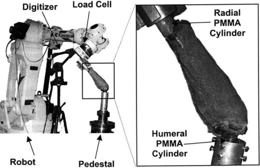
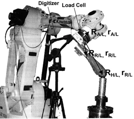
The robotics based joint testing system used in our laboratory consists of a six degree of freedom robotic manipulator, a six degree of freedom load cell attached to the end of the robotic arm, and a three dimensional digitizing system (Figure 4). The digitizer (Microscribe 3DX, Immersion Corporation, San Jose,
CA) was used to construct and find the relative position and orientation of
coordinate systems in the load cell, robot arm, and on the cadaveric joint that was being tested. In this test, the distal radius was attached to the robot arm and the humerus was rigidly fixed to the pedestal beneath the robot. The robot
(UZ1 50, Kawasaki, Japan) was used to very precisely move its end effector to a
given location (repeatability of 0.3 mm, as reported by manufacturer). The load cell (JR3, Woodland CA) allowed for the measurement of the forces applied to
Digitizer Load Cell
Radial PMMA Cylinder H umeral PMMA Cylinder Robot Pedestal
the joint by the robot arm. The force measurements from the load cell and the position measurements from the robot arm enabled the system to operate in both force control and position control modes.
If the system was operating in force control, the robot arm moved the
radius incrementally until a certain target load was reached, as the system recorded the position. Conversely, in position control mode, the robotic arm was moved along a specific path as the resulting force was measured. When used together, these two control algorithms allowed for kinetic and kinematic
measurements to be made on a joint with a minimum of disruption.
In this experiment, with the robot operating in force control mode, a compressive load was applied to the forearm, and the resulting displacement was measured. Then, the IOL was cut, and the previously recorded kinematics were replayed with the system operating in position control mode. The difference in the force measured before and after the IOL was cut was the force in the IOL under the given loading condition by the principle of superposition. The entire system was controlled via personal computer using custom made Visual Basic (Microsoft, Seattle, WA) programs (Appendices A, B, C).
2.2 Specimen Preparation
Eleven fresh frozen human cadaveric forearms, cut at the midhumerus, were used in this study (6 left, 5 right, age 51-72 years). The specimens were thawed overnight at room temperature prior to preparation for testing. The specimens were then assessed via visual examination, palpation, and
fluoroscopy in order to exclude any specimens with gross deformity from the study. The hand and scaphoid were removed to expose the distal radius to enable the insertion of a threaded rod into the intramedullary canal. The rod was cemented in place by injecting bone cement into the bone canal using a syringe. The distal and proximal radioulnar joints were left intact. The distal humeral shaft was cleared of soft tissue and another rod was cemented into the humerus. The bone cement was then used to construct two cylinders-- one around the rod inserted into the radius and the other around the humerus. The distal radius was fixed to the load cell attached to the arm of the robotic manipulator and the humerus was rigidly fixed to a pedestal beneath the robot arm (Figure 4). The pedestal was specially constructed to allow the specimen to be moved in 6 DOF in order to align the specimen with the arm of the robot. The forearm was installed in with the forearm in neutral rotation and the elbow at full extension on the robotic based joint testing system.
2.3 Coordinate Systems for Human Forearm System
The load cell measured the forces and moments applied to it with respect to an internal coordinate system. In order to measure how much force was being applied to the forearm, a coordinate system was created just above the insertion of the rod cemented inside the radius. The position and orientation of the rod coordinate system was found relative to the coordinate system of the load cell, so that the force and moment measured by the load cell could be transformed to the coordinate system of the rod. In order for the robot to move the forearm
appropriately, the position and orientation of the coordinate system of the rod and a coordinate system created at the elbow had to be related to the coordinate system of the robot. The three dimensional digitizer was used to create and relate each of the coordinate systems.
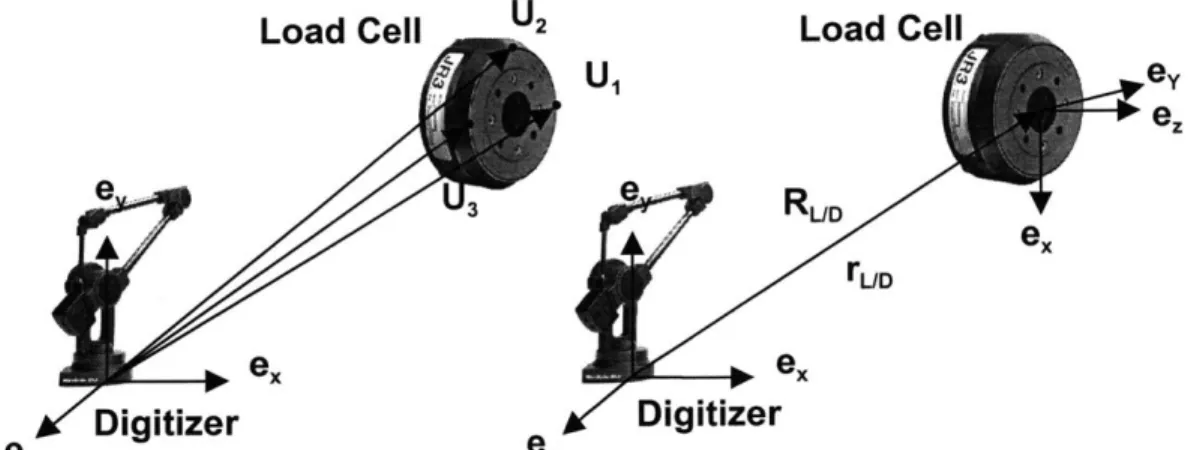
First, a coordinate system was created by the digitizer to be coincident with and parallel to the coordinate system of the load cell. Three points on the edge of the front surface of the load cell were digitized, as shown in Figure 5. The position vector of the load cell relative to the digitizer (rLD), expressed in the coordinate system of the digitizer, was calculated by the following equation:
U,+U3
rUD +
2
where U1 and U3 were the position vectors shown in Figure 5. The y axis of the
load cell was then calculated by:
U, -U3 Y IU, - U3 11
where the double vertical lines denote magnitude of the vector. The z axis was calculated by constructing another vector in the plane parallel to the surface of the load cell and then crossing it with the y axis.
(U1 -U 2)x ey (U1 -U2)xey
Finally, the x axis was generated by crossing the y and z axes. ex =
ey
xez
These three axes were then used to generate the direction cosine matrix relating the orientation of the load cell relative to that of the digitizer
(RUD)-RUD yT ez
The coordinate system of the load cell and the position and orientation of the load cell relative to the digitizer is represented schematically by Figure 5.
Load Cell U2 Load Cell
U ey ee e ... RUD ex rUD ex ex ez Digitizer ez Digitizer
Figure 5. Construction of coordinate system of load cell using digitizer.
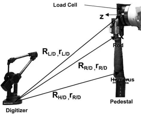
Coordinate systems were also created on the humerus and the rod
cemented to the radius. For convenience, these coordinate systems were
constructed so that they were aligned with the coordinate system of the load cell.
The origin of the humerus coordinate system was located at the midpoint of the
medial and lateral condyles of the humerus and the rod coordinate system was
located in the center of the rod,
just
above its insertion into the radius. The specimen was installed at full extension, with the long axis of the radius alignedwith the x axis of the load cell, and the line formed by the medial and lateral
condyles of the humerus (the approximate axis that the elbow is flexed about)
Load Cell Z
RL/D
,L/DRR/D
,rR/DRH/D
,rR/D Pedestal DigitizerFigure 6. Coordinate systems created using the digitizer. All coordinate systems are aligned initially.
These vectors are then added vectorally to generate the position vectors of the rod with respect to the load cell (rR/D), and the humerus with respect to the load cell
(rH/D)-rH/L H/D ~ rL/D
rR/L . R/D rL/D
Next, they are transformed to the coordinate system of the load cell by the following transformation:
rL =RL/D 'rD
where rL- is a vector expressed in the coordinate system of the load cell, and r' is a vector expressed in the digitizer coordinate system.
The load cell was attached to the robot arm in such a way that both the load cell and robot arm coordinate systems were aligned. The distance between
the robot arm and the load cell was fixed for every test and was known already in the coordinate system of the load cell. Hence, the position (rIL) and orientation
(RAIL) of the coordinate system of the arm of the robot relative to the load cell
coordinate system were known for every test.
The coordinate systems attached to the robot arm, load cell, and rod translated and rotated with the motion of the arm of the robot, as rigid bodies. Hence, the position vectors from the load cell to the robot arm (rIL) and from the load cell to the rod (rWL), both expressed in the coordinate system of the load cell, were constant with any arbitrary motion of the robot arm. The coordinate system attached to the humerus, however, remained fixed throughout the test (Figure 7). A Visual Basic program was written to create all of these calculations and is listed in Appendix A.
Digitizer Load Cell
AL A/L
R/L, rR/L
H/L, ER/L
Figure 7. Schematic representing positions and orientations of coordinate systems relative to load cell. The rod and load cell coordinate systems
2.4 Equilibrium Position of Forearm Under External Loads
To find the equilibrium position of the forearm under an applied load, the system was operated in force control mode. First, the forces and moments applied to the load cell were measured. The reading from the load cell was then transformed to the coordinate system of the rod. The force measured in the two coordinate systems were equal because their axes were always parallel. The moment measured in the load cell coordinate system, however, required manipulation in order to transfer it to the coordinate system of the rod because of the difference in length of the moment arm. The moment in the rod coordinate system was calculated by adding the moment read by the load cell to the cross product of the position vector from the load cell to the rod and the force read by the load cell.
mR _ ML XMLLL/R
The vector containing the forces and moments applied to the radius through the rod (fAPPLIED) was then subtracted from a vector containing the
desired forces and moments that were to be applied to the forearm (fTARGET). The
resulting vector (f) indicates how close the load being applied to forearm is to the target load.
f = fTARGET -APPLIED
If any component of this force and moment vector was less than a certain
tolerance (typically 3 N, 0.3 Nm), then the joint was considered to be at its equilibrium position under the targeted load. If each component of the force
vector is greater than the specified value, a modified Newton-Raphson iteration (Broyden's Method) was implemented in order to find out how much the rod should be moved to minimize the force applied to the radius [12]. Broyden's method was given by:
Aa, = -Bi -f
B-1 = B- + (i,,- ,_ Ag)@A s
-Aa B_1 Af-1
Af,_, = fi -
fi-where i denotes the iteration number, Aa denotes the incremental translation and rotation vector, and B is the Jacobian matrix. For the first iteration, B was assumed to be a diagonal matrix.
The vector Aa, obtained from the Newton-Raphson iteration, was used to generate a translation vector and a rotation matrix. Each component of the translation expressed in the vector Aa was used to create a vector (rR'IR)
expressing the amount of translation in the coordinate system of the rod required to approach the target load. Since the rotation was small, the incremental rotation expressed by Aa was used to generate a rotation matrix relating the current orientation of the rod to a new orientation of the rod
(RR'IR)-RR'/R ~! z 6x C y - 6x 1 )
The symbols Ex, Ey, and s denote incremental rotations about the x, y, and z axes, respectively.
The incremental translation vector (rR'R) was then transformed to the fixed coordinate system of the humerus. The transformation of the translation vector from the rod system to the humerus system was given by:
rR/R = R/H 'rR'/R
where the superscript H and R represent the vector expressed in the humerus and rod coordinate systems, respectively and the T represents the transpose of the matrix. Because rotation matrices are proper orthogonal matrices, their inverse equals their transpose. The rod system and humerus system were aligned initially, so the orientation of the rod coordinate system with respect to the humerus coordinate system (RR/H) was known for the first iteration. After the first iteration, RR/H was updated with the each motion of the robot.
The new orientation of the rod relative to the humerus coordinate system
(RR'/H) was found next. This was expressed in terms of the orientation of the rod
with respect to the humerus (RR/H) and the incremental rotation matrix that was
solved for using the Newton-Raphson iteration (RR'/R).
RR'/H = RR' R -RR/H
The new position and orientation of the rod was then known with respect to the coordinate system of the humerus. This new position and orientation was one in which the vector expressing the difference between the target load and the applied load (f) was minimized with respect to the previous position of the rod.
The amount of movement required by the robot arm in order to produce the desired motion of the rod relative to the humerus (RR'/H R'/H) was solved for
next. The translation of the robot arm expressed in the coordinate system of the humerus (rHA'/A), was given by:
rA/A = RR/H " R/A + rR -R'/H *R/A
rR/A = A/L - rR/L
where the first term in the sum expresses the position of the rod relative to the robot arm in the humerus coordinate system, the second is the translation of the rod in the humerus system, and the third term gives the position of the rod relative to the robot arm after the motion. The position vector of the rod with respect to the robot arm (r/A) was expressed in the coordinate system of the load cell, which was always parallel to the coordinate system of the rod. Finally, the translation of the robot arm in the humerus coordinate system (rHA'/A) was transformed to the global coordinate system of the robot using the following
tranformation:
A/ A G/H * A/A
The matrix describing the new orientation of the rod with respect to the humerus
(RR'/H) was multiplied by the matrix describing the orientation of the humerus with
respect to the global coordinate system of the robot (RH/G). This yielded a matrix
expressing the new orientation of the rod with respect to the global coordinate system of the robot (RR'/G):
RR'/G = RR'/H -RH/G
Since the coordinate systems of the rod and the robot arm were always aligned, the transformations describing the orientation of the robot arm and the rod with
RA'/G = RR'/G = RR'/H -RH/G
The transformation from the global coordinate system of the robot to the coordinate system of the robot arm (RH/G) was generated from the Euler's angles output by the robot when the humerus coordinate system and the coordinate system attached to the robotic arm were aligned before the forearm was moved from its initial position.
Custom made Visual Basic programs (Appendix B, C) were used to measure the force, perform all transformations and other calculations, send the robot the appropriate translations and rotations, and store all force and position data to a file . The new position and orientation of the rod was updated with each iteration, and the entire procedure was repeated until the applied forces and the target forces were within the required criteria.
2.5 Passive Path
In this experiment, the passive flexion path of each specimen was determined first. The passive path was defined as the 5 DOF location of the forearm at each flexion angle (0-90* in 1' increments) in which the forces and moments applied to the forearm were minimized. The passive path served as a reference position to characterize the kinematics of the forearm in response to external loads. When the forearm was loaded, all subsequent displacements were measured with respect to this position and orientation.
To find the passive path, the equilibrium position was determined using the above procedure with the target forces and moments set to zero and the
flexion angle of the elbow fixed. In order to fix the flexion angle, the incremental rotation about the y axis (Ey, found from the Newton-Raphson iteration) was set to zero. Because the flexion angle was constrained, the moment about this axis was not constrained. After the force and moment criteria were satisfied (except for the moment about the flexion axis), the arm was flexed one degree. The new orientation of the forearm was calculated in the same manner as described in the previous section. The matrix describing the current orientation of the rod with respect to the humerus (RR/H) was pre-multiplied by the transformation from the current orientation of the rod to new orientation of the rod (RR'/R). Instead of RR'/R
being an incremental rotation calculated from the Newton-Raphson iteration, however, it is a direction cosine matrix expressing a rotation about the y axis of the rod.
(cos(1*) 0 -sin(1 )'
RR'/H = 0 1 0 -RR/H
sin(10) 0 cos(1 ))
The translation of the rod was solved for by applying the same rotation to the position vector of the rod to the humerus.
rcos(10)
0 -sin(10)rR'/H 1 0 R0 HrRH
sin(10) 0 cos(10)
The robot arm was then moved appropriately, as described in the previous section.
Similarly, another passive path was found in order to rotate the forearm to
example, at 300 of flexion along the passive path, the forearm was pronated to
450-- with the elbow flexion angle fixed-- by incrementally rotating and translating
the forearm to minimize forces.
2.6 Displacement of Radius and Force in IOL Under Compressive Loads
After finding the passive path, the robot applied a 100 N compressive load along the long axis (x axis) of the radius at 00, 30', 600, and 900 of flexion with the forearm pronated, supinated, and in neutral forearm rotation. The robot, again acting in force control mode, recorded the displacement of the forearm during each loading condition.
Next, the IOL was then transected via the following approach. An approximately 8 cm incision was made on the subcutaneous border of the ulna in its midshaft. Dissection was carried down to the bone and around the volar surface of the ulna to the 1OL. The IOL was then dissected along its entire length by passing an elevator or blade along the ulna. The distal and proximal radioulnar joints were not disrupted. Confirmation of the transection of the IOL was obtained by visual inspection and palpation. The soft tissue envelope surrounding the forearm was otherwise left intact. The wound was then sutured.
Finally, the kinematics measured with the IOL intact were replayed by the robot. Simultaneously, the load cell measured the force applied to the forearm. Using the principle of superposition [8], the change in force before and after transection of the IOL represented the in-situ force in the IOL under a given loading condition. After the testing of each specimen, the forearm was dissected
to verify that the IOL was completely transected along its length and that it was free of pathology. A repeated measures analysis of variance with within factors was performed to detect statistically significant differences in IOL force and the displacement of the radial head between pronation, neutral, and supination (p
<0.05).
2.7 System Validation
As was mentioned previously, the principle of superposition was used to find the force in the IOL. A 100 N compressive force was applied to the forearm, and the resulting kinematics were measured. These kinematics were then replayed by the robot after the IOL was cut. The difference in force before and after the transection of the IOL gives the force in the IOL, by the principle of superposition.
In order for the principle of superposition to be valid in this experiment, however, both the radius and the ulna must be in nearly the same position before and after the cutting of the IOL. If this condition were not met, indicating a relatively large deformation of the radius and ulna, an inaccurate measurement of the force in the IOL would result. Therefore, it was necessary to verify that the assumption that the radius and ulna were rigid bodies was a reasonable one.
For two of the ten specimens, pins were inserted into the radius and ulna in their midshaft. A stab incision was made on the subcutaneous border of the ulna over its midshaft and a 0.6 mm K-wire was inserted into the cortex and cut flush with the bone. Similarly for the radius, a stab incision was made over its
midshaft on the dorsoradial surface and another K-wire was inserted and cut flush with the bone.
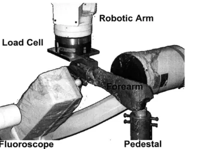
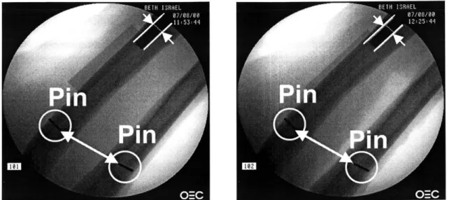
When the forearm was at its final equilibrium position under the 100 N load in pronation, supination, and neutral, with the IOL intact, fluoroscopy was used to create x-ray images of the radius and ulna in their midshaft (Figures 8 and 9). The x-ray images captured the position of the pins, as well as a portion of the threaded rod used to load the radius. The forearms were again x-rayed under the 100 N load, in each forearm position, after the cutting of the IOL. All images were then saved as bitmaps and the distance between the pins before and after the cutting of the IOL was measured using an image processing software for the PC (Canvas, Deneba Software, Miami, FL).The distance was scaled by measuring the diameter of the threaded rod that was inserted into the radius.
Fluoroscope Pedestal
Figure 8. Flouroscope used to measure position of pins with forearm under 100 N compressive load, before and after transection of IOL
Figure 9. X-ray images used to validity of superposition in calculating the force in the IOL. The distance between the pins was measured before (left) and after (right) transection of IOL. The diameter of the threaded rod was used to scale the
Chapter 3: Results
3.1 System Validation
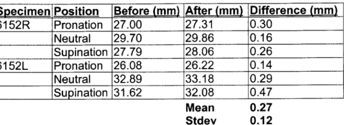
The distances measured between the pins implanted into the radius and ulna while the forearm was under a 100 N load are summarized in Table 1. The distances between the pins (Figure 9) in each forearm position before the IOL was cut are listed in the first column, and the distances after the IOL was cut are listed in the second column. Under a 1OON compressive load applied to the radius, the distance between the two pins in specimen 6152R, while at full extension and in pronation, was 27 mm before the IOL was cut. After the IOL was cut, the distance was measured as 27.3 mm. The difference in the distance that was measured between the pins before and after the cutting of the IOL was
0.3 mm. This value represents the deformation of the radius and the ulna
caused by the IOL tension when the forearm was under the external load. Similar values were obtained in other forearm positions for this specimen and for specimen 6152L. The mean difference between the two measurements before and after the transection of the IOL was 0.27 ± 0.12 mm. The component of this difference measured along the direction of the long axis of the radius may cause errors in the measurement of force in the IOL, since this component may cause change in the contact force in the radiocapitellar joint. However, since the component of this measurement along the long axis of the radius was extremely small (< 0.05 mm), its effect on radiocapitellar joint contact is negligible. Therefore, the principle of superposition could be applied in this experiment.
Specimen Position Before (mm) After (mm) Difference (mm) 6152R Pronation 27.00 27.31 0.30 Neutral 29.70 29.86 0.16 Supination 27.79 28.06 0.26 6152L Pronation 26.08 26.22 0.14 Neutral 32.89 33.18 0.29 ____ _ ISupination 31.62 32.08 0.47 Mean 0.27 Stdev 0.12
Table 1. The distance between pins implanted into the radius and ulna before and after cutting of IOL. This measurement was made while the 100 N load was being applied to the forearm. The difference between these two measurements is given in the third column.
3.2 Displacement of Radius
A typical plot of radial displacement versus the applied force (up to 100 N)
is shown in Figure 10. This test was performed with the specimen at 30 degrees of flexion and in 45 degrees of supination. When the load was low, the displacement increased sharply with the load. The forearm is rather compliant under low loads. However, as the load increased, the forearm becomes stiffer, and the displacement increases at a lower rate. At 30 N of applied load, the displacement of the radius was about 0.9 mm. As the applied load increased to
100 N, the displacement of the radius increased to about 2 mm of displacement.
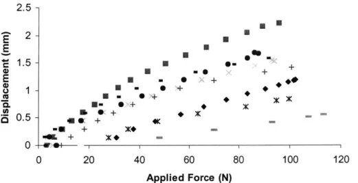
Similar displacement versus applied load curves were observed in all of the specimens (Figure 11).
1233 Supination 300 E E ,1.5 -+ E
{0.5
- + 0*
0 20 40 60 Applied Force (N)Figure 10. Displacement versus applied specimen at 300 of flexion and in supination.
E E 0 a. .5. a 2.5 2 1.5 1 0.5 n - 4K -u+ +~ X -- + x+ 4. e + I X 0 a+ * ~ x+ U O-80 100
load for a typical
X X
++
0 20 40 60 80 100 120
Applied Force (N)
Figure 11. Displacement versus applied load for all specimens at 300 of flexion and in supination
The displacement of the radius at 100 N applied load was then averaged for all of the specimens at each flexion angle and in each forearm position (Figure 12). The displacement of the radius in response to the axial compressive load varied with elbow flexion and forearm rotation. A 100 N axial load applied to
the distal radius resulted in a displacement of 0.6 ± 0.1 mm (mean ± SD) when
the elbow was fully extended and the forearm in neutral rotation. The displacement increased with increasing flexion. At 900 of flexion with the forearm
in neutral, axial displacement reached a maximum of 1.8 ± 0.6 mm, as shown in
Figure 12. With the forearm pronated, the displacement of the radius also increased as flexion increased. The axial displacement was 1.0±0.4 mm at full extension and 1.6 ± 0.5 mm at 90 degrees of flexion. A similar pattern was
observed with the forearm in supination - at full extension, displacement was
0.9±0.3 mm (p < 0.05 compared with neutral), and this steadily increased to
1.7±0.5 mm at 90 degrees of flexion.
At full extension, the average displacement in pronation and supination were very similar (1.0 mm in pronation versus 0.9 mm in supination). The displacement in neutral, however, was significantly lower (0.6 mm) than the displacement in pronation or supination. A similar trend was observed at 30' of elbow flexion. At 60 , the displacements were almost the same in pronation, neutral, and supination (1.5 mm, 1.5 mm, and 1.6 mm, respectively). This was also observed at 900 of flexion where the displacements in pronation, neutral, and supination were 1.6 mm, 1.8 mm, and 1.7 mm, respectively.
3-*
2.5
-2
*
E
Pronation
1.5
-
E Neutral
1 -0
Supination
0.5
0
30
60
90
Flexion Angle
(0)Figure 12 Plot of axial displacement versus flexion angle in pronation, neutral, and supination. An asterisk denotes p > 0.05.
3.3 Force in the IOL
The in situ force in the IOL versus the force applied to the radius is plotted in Figure 13 for a specimen at 30 degrees of flexion with the forearm in supination. The force in the IOL also increased linearly with the applied load. For this test, with no applied load, a 10 N force was measured in the IOL, and with a 100 N applied load, a 50 N force was measured. Similar linear relationships between IOL force and applied load were obtained for all specimens (Figure 14).
1233 Supination 300
40 60
Applied Force (N)
Figure 13. IOL force versus applied load for specimen at 300 of flexion and in supination.
z %... 0 U. 100-90 -80 - 70-60 - 50- 40-30 - 20-10 -X X. 0 0 0 , 4 20 40 I 1 1 60 80 100 Applied Force (N)
Figure 14. IOL force versus applied load for all specimens at 30* of flexion and in supination
50 40 30 20 10 0 0 LL -j
2
. . 0 20 80 100 a typical X Ar 0 0 C C~0 + 120 XIThe average in-situ IOL force under a 100 N axial compressive are shown in Figure 15. The force in the IOL varied with both flexion of the elbow and the position of the forearm. In neutral forearm rotation, the IOL force steadily increased from a low of 7.6 ± 4.8 N at full extension to a maximum of 19.4 ±
24.9 N at 90 degrees elbow flexion. The force-elbow flexion curve for pronation showed a different pattern. The maximum IOL force was measured at 30 degrees (30.0 ± 30.7N) and subsequently declined to 19.5±21.9N at 90 degrees
of flexion. The minimum IOL force, however, was recorded at full extension
(11.2 ± 12.3N). A similar pattern was noted with the forearm in supination. At
full extension, the force was the lowest (30.6 ± 31.3N). At 30 degrees it reached
a maximum of 42.9 ± 31.5N, and then the force declined steadily to 33.8 ± 33.7 N at 90 degrees flexion.
0
L--j0
100-80
*
60 - Pronation . Neutral 40 - Supination 20 -0 0 30 60 90Flexion Angle
(0)
Figure 15. Plot of IOL force versus flexion angle in pronation, neutral,
At all flexion angles, the highest force measured when the forearm was in supination. At full extension, the force in supination (30.6 N) was significantly higher than the force in pronation (20.9 N) or neutral (7.6 N). This was also true at 900 of flexion (35.6 N in supination, 20.9 N in pronation, 15.4 N in neutral) At
30* and 60' degrees of flexion, there was a statistically significant difference
between supination and neutral, however, there was no significant difference detected between supination and pronation. Throughout all flexion angles, the average force transferred from the radius to the ulna was 36%, 21 %, and 15% of the applied forearm load in supination, pronation, and neutral, respectively.
3.4 Analysis of left versus right forearms
By observing the force data for each pair of specimens, we noticed that
there was a marked difference between left and right forearms from the same donors. For example, the force in the IOL at full extension was 6.6 N in neutral,
7.0 N in pronation, and 8.2 in supination for specimen 1508L, a left forearm
(Figure 16). Comparing this to the matching right forearm specimen 1508R, the forces in the IOL were 7.0 N, 39.2 N, and 64.0 N in neutral, pronation, and supination, respectively. For the right arm in full extension, fairly large force measurements were obtained with the forearm in pronation and supination, as compared to the left arm. At 30' of flexion, however, there were larger forces in the IOL in the left forearm than in the right. The left forearm had IOL forces of
16.1 N, 60.9 N, and 69.9 N in neutral, pronation, and supination, respectively, as
the left forearm were larger than those in the right at 60 and 90 degrees of flexion as well. Differences between the forces measured in the IOL for left and right forearm specimens were observed in all five matched pairs that were tested (Figure 16). A plot of the average force in the IOL for all of the left forearms in each matched pair is shown in Figure 17. For the left forearms in pronation, the
maximum force was transferred across the IOL when the elbow was flexed at
300 (52.4 ± 30.8 N). The force then decreased with increasing flexion to 28.4 ±
23.4 N at 90* of flexion. The minimum force of 9.8 ± 11.1 N was measured
when the forearms were in full extension. When in neutral, the force transferred across the IOL of the left forearms steadily increased with increasing flexion from
8.1 ± 5.2 N at full extension to 31.3 ± 32.6 N at 900 of flexion. The trend
observed when the forearms were in supination was similar to the trend observed in pronation. Maximum force was measured at 30' of flexion (73.6 ± 5.2 N), with steadily decreasing force as flexion increased to 900 (61.7 ± 30.6 N),
and minimum force at full extension (8.4 ± 2.51 N).
The forces measured in the IOL in the right forearms were quite different from the forces in the left forearms (Figure 18). When the forearm was in
pronation or supination, maximum force was measured at full extension (13.7 15.4 N in pronation and 58.0 ± 26.9 N in supination). Relatively small forces were measured in pronation and supination at other flexion angles. The
maximum force in neutral (14.6 ± 11.7 N) was measured when the forearm was
at 300 of flexion. These data were obtained from only five pairs of specimens, however. More matched pairs need to be studied in order to quantify the effect
of right or left handedness on the biomechanical function of the IOL in the human
mSOL 100 - - - - - -60 _ - E- 0 M Pronstio Oinatim 0 0 30 60 90 Flexion Angle (degrees)
100-E3 Nudral 60 -m aron IL 40 - 4in ti on -j 2) QS4Irnn 0 0 30 60 90
Flexion Angle (degees)
6151L 100 60-Ei utra ~60 Pronabon U0. 40 [S4Linatimn IL 2 -0 0 0 30 60 90
Flexion Angle (degrees
00615XL 100 - - - - -160. 8 60 - - ---- -u. 40 - - --- -0 2 0 30 60 90
Flexion Angle (degrees)
146L 10 40-~M Pron 40 - - - --- t -2) --- --- QS4inrtimn 0 3D 6D 90
Flexion Angle (degees)
100 --- - ~80-? "E Natrai C 60-0 Prtution LL 40 -oLi~a 0 20--0 0 30 60 90
Flexion Angle (degres)
100 - - - - - ~ - - - ~~ 80. MNatral ~~ ftrnafio L 40 - ----1~ 1IStiration 0 2 "-"-0 3D 60 90
Fexion Angle (degrees)
6151R 100 -E Nutri ~60 *tncS PrOnSticn LL [3 SLenatio 0 0 30 60 90
Rexion Angle (degres)
006153R 100 - -- - - -860 0 1 ng Prontion L. 40 ci SLpination 0-20 0-0 30 60 90
Flexion Angle (degrees)
1465R
100 _
0 3 60 60
Oexion Angle (deges)
Figure 16. Plot of force in the IOL versus flexion angle with the forearm in pronation, supination, and in neutral rotation for matched forearms. The left forearm is on the left, and the corresponding right forearm, on the right.
38 F 4) 0 IL -j 0 I I
0 z 0, U -0 100 90 80 70 60 50 40 30 20 10 0 60 Pmnalo 50 E~eu- m M Pronaion M kuiral 0 Supination 60 0 30
Flexdon Angle (degrees)
Figure 17. Average force in IOL under 100 N compressive load for left forearms. 100 S80-0 __60 _ _IM Pronation z 50- - Nkuiru l 40 0 Supinaion u 30 -0 10-0 30 60 90
Fledon Angle (degrees)
Figure 18. Average force in IOL under 100 N compressive load for right forearms.
Chapter 4: Discussion
This study investigated the biomechanical function of the IOL in an intact forearm. The in situ force in the entire length of the IOL and the axial displacement of the radius were measured under uniaxial compressive loads applied to the radius. Our measurements were obtained with no disruption of the bones and minimal disruption of the soft tissues surrounding the forearm. The results indicate that the IOL plays a significant biomechanical role in the transmission of force in the forearm. The amount of force that the IOL transfers depends on whether the forearm is in pronation, supination, or neutral and changes with flexion of the elbow. At all flexion angles, the IOL force in supination was greater than the force in pronation and neutral.
Morrey et al [11] measured the force transferred through the radial head under simulated muscle loads. They dissected the forearm down to a bone-ligament complex and implanted a load cell into the radial neck. Contact force was measured as the forearm was flexed in both pronation and supination. They found that the force transferred via the radiocapitellar joint was greater in pronation than in supination. This implies that when the forearm is in pronation, less force is transferred across the IOL. In supination, however, less force is transferred across the radiocapitellar joint, suggesting that there is a higher force in the IOL.
Hotchkiss et al [6] measured the stiffness of the IOL in forearms with the radial head excised under axial compressive loads applied to the radius. They
measured the stiffness of the IOL in pronation, supination and neutral with the elbow flexion angle fixed at 90 degrees. The maximum stiffness of the IOL was found in supination (134.7 N/mm), implying that a higher force is transmitted through the IOL when the forearm is in supination, as compared to pronation (74.3 N/mm). This study, however, did not look at the role of the IOL in the intact forearm. Rather, it found that the IOL is an important constraint in forearms that are without radial heads.
Birkbeck et al [1] measured force in the IOL under applied axial loads through the metacarpals. They inserted cantilever load cells into the proximal and distal radius and ulna in order to measure the relative contribution of the applied loads with the elbow fixed at 90 degrees before and after sectioning of the IOL. They found that the IOL transfers about 17%, 6%, and 6% of the applied load when the forearm was supinated, pronated, and in neutral, respectively.
The overall trend observed in these results are in agreement with our observations that the IOL transfers higher loads from the radius to the ulna in supination than other positions of the forearm. However, we were able to make our measurements across the full range of motion of the forearm and with minimal disruption to the bones and soft tissues of the forearm. Therefore, our results give a more accurate picture of the function of the IOL in the intact forearm.
Markolf et al [9, 10] implanted load cells into the distal radius and the proximal ulna, and a strain gauge into the central band of the IOL. They
applied compressive loads to the metacarpals in various positions of the forearm. In their experiments, all soft tissues were removed from the forearm except for the central band of the IOL and joint capsule. They measured the force in the distal radius and proximal ulna and the strain in the IOL with the forearm in varus and valgus alignment. They do not directly report the force in the IOL, however.
A direct comparison of our results to that of Markolf et al is difficult.
In another study, Pfaeffle et al [14] measured the force in the IOL using a technique similar to that of Markolf et al. They implanted 6 DOF load cells in the distal radius and proximal ulna. The central one third of the forearm was dissected down to IOL and bone, and then the IOL was dissected down to its central band. They applied a 136 N axial load through the hand with the elbow at full extension. They measured forces of 15 N, 31 N, and 20 N (11%, 23%,
15%, of applied load) in pronation, neutral and supination, respectively. These
results are different than those obtained in this study. We measured forces of 11.2 N, 7.6 N, and 30.6 N in the IOL under a 100 N compressive load in pronation, neutral and supination, respectively. Furthermore, in our experiment, the largest force in the IOL was found in supination at all flexion angles.
The differences in the results of our study and the study of Pfaeffle et al can be attributed to differences in the experimental setups. In our study, the bones and soft tissues of the forearm were left intact. In Pfaeffle's experiment, the bones were disrupted to enable the insertion of load cells, and only a bone-ligament-bone complex was tested. In our study, the contribution of the entire
IOL was measured, and in theirs, only the contribution of the central band of the IOL was measured.
Schneiderman et al [16] observed that anatomically, the IOL has a number of thickened bands throughout its length and suggested that the interosseous membrane should be termed the interosseous ligamentous complex. They also suggested that the strain in different portions of the IOL is not uniform and varies with different positions of the forearm. A similar
observation of the anatomy of the IOL was noted in this study. Figure 19 shows pictures of the IOL in three typical forearm specimens. There are a number of substantial bands in the interosseous space, rather than just one distinct central band. The reported width of the central band measured perpendicular to the fiber orientation varies greatly in the literature. Hotchkiss et al [6] reported this to be 2.6 cm while Skahen et al [18] reported a width of 1.1 cm. This implies that either there is a great variation in the width of the central band, or that identifying it is difficult. Measuring the force in only the central band of the IOL may underestimate the function of the entire IOL in forearm stability. Therefore, we assessed the force transferred by the IOL across its entire length, rather than just the central band.
Clinically, most radial head fractures occur with the forearm pronated. In this position, according to our results, the radial head is not as protected by the IOL as it would be in supination. The IOL carries less load in pronation, as compared to supination, and hence, the contact force in the radiocapitellar joint is greater, as compared to supination. Therefore a large axial load, such as that
which occurs during a fall on an outstretched hand, (with the forearm pronated and the elbow extended) would have most of the impact transmitted through the radial head, increasing the likelihood of radial head fracture. Similar conclusions were made by Morrey et al [11].
Our results suggest that when treating a radial head fracture, the forearm should be positioned in supination as noted by Morrey et al [11]. In supination, there is maximal force transferred across the IOL, as shown in Figure 13. This would minimize the forces transferred across the radial head, protecting it (or its fixation) from large forces while it heals.
Figure 19. Photographs of IOL in several forearm specimens. The IOL runs along most of the length of the forearm. A distinct "central band" is difficult to identify.
Chapter 5: Conclusion and Future Work
5.1 Conclusion
A system was developed and successfully implemented to measure the
force in the IOL under compressive loads applied to the forearm at different flexion angles and forearm positions. In order to validate the system, pins were implanted into the radius and ulna and the distance between them was measured using x-ray images before and after the transection of the IOL. This measurement indicated that the amount of deformation of the radius and ulna under the applied load was small, and that our use of the principle of superposition was valid for the measurement of the force in the IOL. The system allowed for minimum disruption of the soft tissues surrounding the forearm and no disruption of the bones of the forearm. The force in the entire IOL could be measured under compressive loads to the forearm, rather than just the force in the central band, as in other experiments. Therefore, this system can provide measurement of the IOL force that is more accurate than the current studies in the literature.
Our results indicated that the IOL plays an important biomechanical role in intact forearm. The amount of load that the IOL transfers depends on the position of the forearm, and the flexion angle of the elbow. The maximum force in the IOL was measured in supination at all flexion angles. The maximum force was measured in supination, at 30* of elbow flexion, where the IOL carried up to 43% of applied load.
These results have important clinical implications. This study had demonstrated that IOL is important structure in normal forearm function. When treating injuries to the forearm and elbow, fractures to the radial head, clinicians should examine the integrity of the IOL. If the IOL was ruptured, then a reconstruction may be necessary. Furthermore, these results imply that fracture of radial head is more likely with forearm in pronation, because radial head is less protected by IOL in this position. This is confirmed by clinical observations. Finally, the forearm should be kept in supination when treating radial head fractures to minimize the force transferred across radial head and maximize force across IOL.
5.2 Future Work
This study measured the force in the IOL and the displacement of the radius under passive loads to the forearm. Daily function of the forearm involves the contraction of muscles. The function of the IOL under muscle loads will be simulated by hanging weights from a system of pulleys connected to the major muscle groups of the forearm. This will simulate forearm function during such daily activities as pushing open doors or lifting heavy bags of groceries.
As observed in our results, it seems that the IOL has a distinct difference in load transmission betweeen left and right forearms. Future study will evaluate this phenomenon under various physiolocial loading conditions. This knowledge will enable the clinician to better treat ruptures of the IOL in forearm injuries.
References
1. Birkbeck, D. P., Failla, J.M., Hoshaw, S.J., Fyhrie, D.P., Schaffler, M.
(1997). "The interosseous membrane affects load distribution in the
forearm." J. Hand Surg., 22A, 975-980.
2. Curr, J. F., Coe W. A. (1946). "Dislocation of the interior radio-ulnar joint."
British Journal of Surg, 34(74).
3. Essex-Lopresti, P. (1951). "Fractures of the radial head with distal radio-ulnar dislocation." J. Bone Joint Surg., 33B, 244.
4. Halls, A. A., Travill, A.,. (1964). "Transmission of pressures across the elbow joint." Anat. Rec., 150, 243-248.
5. Herndon, J. H. (1999). Surgical Reconstruction of the Upper Extremity, Appleton & Lange, Stamford, Connecticut.
6. Hotchkiss, R. N., An, K.N., Sowa, D.T., Basta, S., Weiland, A.J. (1989). "Anatomic and mechanical study of the interosseous membrane of the forearm: pathomechanics of proximal migration of the radius." J. Hand
Surg., 14A, 256-261.
7. Hotchkiss, R. N. (1994). "Injuries to the Interosseous Ligament of the Forearm." Hand Clinics, 10(3), 391-398.
8. Li, G., Rudy, T. W., Sakane, M., Kanamori, A., Ma, C. B. and Woo, S. L. Y.
(1999). "The importance of quadriceps and hamstrings muscle loading on
knee kinematics and in-situ forces in the ACL." J Biomechanics, 32, 395-400.
9. Markolf and Hotchkiss, L. D. Y. S. M. R. (1998). "Radioulnar Load - Sharing in the Forearm." Bone of the joint surg, 80A, 879-888.
10. Markolf, K. L. D. A. M. H. K. (2000). "Mechanisms of Load Transfer in the
Cadaver Forearm: Role of the Interosseous Membrane." J Hand Surg, 25A,
674-682.
11. Morrey, B. F., An, K.N., Stormont, T. (1988). "Force transmission through the radial head." J. Bone Joint Surg., 70A, 250-256.
12. Most, E. (2000, June). "Development of a 6-DOF Robotic Test System for Studying the Biomechanics of Total Knee Replacement." Master of Science in Mechanical Engineering, MIT, Cambridge.