Automated Precision Three-Axis Scanner and Velocity Sensor for Laser
Dermatology
by
Tang Yew Tan
M.Eng., Mechanical Engineering,
Imperial College of Science, Technology and Medicine, London, 1997
Submitted to the Department of Mechanical Engineering in Partial Fulfillment of the Requirements for the Degree of
Master of Science in Mechanical Engineering at the
Massachusetts Institute of Technology January 1999
@1999 Massachusetts Institute of Technology All Rights Reserved
Signature of A uthor... ... ...
Department of Mechanical Engineering January 15, 1998
Certified by... ... .... ... Dr. Andre Sharon Executive Officer of the Manufacturing Institute Thesis Supervisor
A ccepted B y ... ...
Ain A. Sonin Chairman, Department Committee on Graduate Studies
Automated Precision Three-Axis Scanner and Velocity Sensor for Laser Dermatology
by
Tang Yew Tan
Submitted to the Department of Mechanical Engineering on January 15, 1999 in Partial Fulfillment of the Requirements for the Degree of Master of Science in
Mechanical Engineering
ABSTRACT
Automated computer controlled systems are increasingly integrated into laser
applications for the medical field. This helps improve system performance, which results in better surgical processes. Laser dermatology represents one of the new challenges in this field. The development of an automated precision three-axis scanner will help increase laser process throughput and consistency.
This dissertation describes the development of a computer controlled scanner for laser-based permanent hair removal. Clinical trials performed on the integrated scanner-laser system showed a faster application rate and better process consistency compared to the conventional manual technique. Tests also indicated that a better velocity sensor has to be developed to obtain actual relative velocity with respect to the skin. This would allow the
scanner system parameters to be adjusted in real-time. The second phase of the
dissertation describes the development of a velocity sensor that can cope with the elastic characteristic of human skin. Experiments were performed on contact and non-contact
types of sensors and the results are discussed.
Thesis Supervisor: Dr. Andre Sharon
Acknowledgement
Dr. Andre Sharon, for giving me the opportunity to work on the project and providing
unconstrained guidance.
Dr.Altschuler, Paul , Rick and the Palomar team, for the help and inspiring ideas.
Min , I aspire to reach your state of intellectual nirvana. Am sure snowboarding regularly
will help. Thanks for everything.
Sieu, for the joy and laughter, the food (even the hidden ones), the bucket of change, the bad taste in music and the inspiring thoughts.
Pankaj, for reminding me to take my meals and being a good buddy. Maybe next time
I'll let you document my project.
Jason, for expanding the horizons in my mind. The 60's was in the past, but for someone who thinks fish is spelled with a 'ph', I'll let that pass.
Wayne, for the loan of your sports car, advice and interesting thoughts. Dai, for the mental sparing and keeping me on my toes
Prakash, Brian and Mike, for taking entertainment to a new dimension.
Jamie, Amir and Fardad, for being great stress relievers and friends. Brady power! Victor, for the smiles and cheerfulness that have helped a tremendous amount.
To all the other friends at MIT who have helped make this experience a memorable one.
My family and Celine, for the support, encouragement and love. I wouldn't have gone
IN TR O D U C TIO N ... ... --7
1.1 PROJECT INITIATIVE...---.8
1.2 PROPOSED A PPROACH...-9
1.3 BACKGROUND ON LASER TECHNOLOGY ... 10
1.4 O PTICAL PROPERTIES OF TISSUE... 12
1.4.1 Absorption ... 12
1.4.2 Scattering...13
1.4.3 Radiation Penetration Characteristics ... 13
1.5 LASER - TISSUE INTERACTION... 16
1.5.1 Photochem istry ... 16
1.5.2 The rm al Effects... 17
1.5.3 Non-Thermal or Ionizing Effects ... 18
1.6 LASERS IN SURGERY AND MEDICINE: CURRENT APPLICATIONS... 19
1.7 LASER DERM ATOLOGY...21
1.7.1 Vascular Lesions and Port W ine Stains... 22
1.7.2 Skin Lesions...22
1.7.3 Tattoo rem oval...22
1.7.4 Plastic surgery...23
1.7.5 H air Rem oval...23
1.8 LASER HAIR REM OVAL ... 24
Palom ar E2000'" Ruby Laser System ... 26
2 DEVELOPMENT AND DESIGN OF AN AUTOMATED PRECISION SCANNER...32
2.1 FUNCTIONAL REQUIREMENTS AND CONSTRAINTS ... 32
2.2 D ESIGN ISSUES...35
2.2.1 G eneral Concepts ... 35
2.3 DESIGN CONCEPTS AND SELECTION... 41
2.3.1 Z-Stage D esign Alternatives and Concept Selection ... 41
2.3.2 Y-Stage Final Design...45
2.3.3 X-Stage D esign...46
3 SY STEM M O D ELIN G AND CO N TRO L...47
3.1 SYSTEM MODELING... ... --.... - ---... 47 3.1.1 X & Y Stages...----...----...47 3.1.2 Z-Stage...48 3.1.3 D C-M otor schematics... ...49 3.2 SYSTEM CONTROL...---..50 3.2.1 X & Y Axes...53 3.2.2 Z Axis...56
3.3 FORCE SENSING FOR THE Z-AXIS... 58
3.3.1 System response to external load...58
3.4 COM MUNICATION BETWEEN LASER SYSTEM AND SCANNER ... 62
3.5 U SER INTERFACE ... 63
4 EXPERIMENTATION WITH MIT/MI SCANNER...64
4.1 X -AxiS PERFORM ANCE...65
4.2 Y -AxIS PERFORM ANCE...67
4.3 Z-STAGE PERFORMANCE ...---...--- 68
4.4 SCANNER-LASER INTERACTION PERFORMANCE ... 71
5 V ELO CITY SEN SO R ... 74
5.1 FUNCTIONAL REQUIREMENTS AND CONSTRAINTS...76
5.2 ROTARY ENCODER BASED VELOCITY SENSOR ... 78
5.2.1 System design...78
5.2.2 Experim ental Results... .. 79
5.3.1 System D esign...80
5.3.2 Experim ental Results ... 81
5.4 M INIATURE TACHOMETER ... 82
5.4.1 Experim ental Results ... 83
5.5 INFRARED-BASED V ELOCITY SENSOR ... 88
5.5.1 Experim ental Results...90
5.6 BACK SCATTERING BASED VELOCITY SENSOR ... 92
5.6.1 Experim ental results...98
6 C O N C LU SION ... 101
6.1 M IT/M I A UTOM ATED PRECISION SCANNER ... 101
6.2 V ELOCITY SENSOR...109
1 Introduction
Automated computer controlled systems are increasingly integrated into generic appliances and sophisticated equipment, helping enhance and improve product
performance. The spectrum of applications ranges from household washing machines to intelligent cruise missiles. Computers have increased in capacity and performance over the years making it possible to push the envelope in technological advancements. In the laser-medical field, various techniques such as laser pulsing, beam scanning and laser pulse generation rely on computer control. This has improved the overall performance of
laser systems resulting in better surgical results. The applications of laser systems in medical surgery are wide and varied.
This dissertation presents the motivation of developing a versatile automated computer controlled machine specifically for laser dermatology applications. There are two main sections to this dissertation. The first section focuses on the development and design of a scanner for automating the laser hair removal process in dermatology applications. The second addresses the challenges and methodologies involved in developing a velocity sensor for the scanner that would provide actual relative velocity
data between the skin and the laser hand piece.
Laser dermatology is a growing field and this chapter will provide a brief introduction to laser technology and the critical processes involved in laser-tissue interaction. Various laser systems used in the medical field will be briefly described as well as their application in laser dermatology.
1.1 Project Initiative
The potential market for laser dermatology applications exceeds $ 1 billion dollar in the United States. Apart from creating a product that has superior laser light properties for good photothermolysis performance, speed and reduced discomfort to the patient are the other important factors that would help determine the success of a laser product.
The MIT Manufacturing Institute (MIT/MI) scanner was developed to address the speed, consistency and comfort issues of the laser procedure. The scanner was designed to penetrate high-volume medical practices since both providers and consumers will benefit from dramatically improved speed, ease of use and reliability. The first prototype was designed to compliment the Palomar E2000T system. Palomar Medical
Technologies, Inc. is a leading developer and supplier of proprietary laser systems for hair removal and other cosmetic laser treatments.
The development of an automated precision scanner helps control the laser process by creating a precise and reproducible operation. This machine is used to
accurately position the laser hand piece at the desired location in minimum time. The machine also serves to automate tedious, repetitive and time-consuming processes. Laser hair removal was chosen as the dermatological process to be initially addressed as the current techniques are prone to positional error and tend to be very time consuming. Currently, an operator has to manually position and apply a firm force on the laser hand piece in small adjacent steps across a large skin surface. Most laser lenses have a spot size of approximately 10mm and a considerable time is required to process large patches of skin such as on the leg, thigh and back. Inaccurate positioning could also create zones of gross multi-overlapping that can cause epidermal injury.
1.2 Proposed Approach
In 1997, the MIT/MI proposed the development of a 'proof-of-concept' prototype precision scanner for laser dermatology applications that would have mass production potential. The prototype scanner would have to be flexible in both its mechanical design and user interface. Most of the working variables would be changed through software to facilitate the identification of the critical variables. The scanning quality of the laser beam in the operating field is not only a function of the planar displacement of the X-Y
Axes, but also of the Z-axis. This necessitates precision motion of the laser scanner in all three-axes.
The initiative to investigate different and new velocity sensing mechanisms was motivated by the need to develop a simple and inexpensive method that can directly detect the relative velocity between the device and the skin surface. Skin has an elastic characteristic that could provide erroneous results with current velocity sensing methods available in the market.
1.3 Background on Laser Technology
Laser is the acronym for Light Amplification by Stimulated Emission of Radiation. Albert Einstein described the underlying principle of a laser in 1917 and the
first practical demonstration took place in 1960 when Theodore Maiman successfully stimulated a ruby crystal to produce laser light of 690nm. Within a year, the use of lasers had expanded to include ophthalmology for photocoagulation. This set the stage for further development of other lasers working at different wavelengths. Today, the
applications of lasers have increased tremendously and span almost every field of human endeavor.
Laser light is produced by the action of the excited state of a large population of atoms or molecules that have absorbed energy from an external source. The process begins with the spontaneous release of energy by a small amount of excited states, producing photons of light in the laser medium. These photons in turn initiate a chain reaction of identical photon emissions in other excited states that are encountered. This phenomenon of emissions is the underlying process that creates laser light.
Three properties of laser light (Figure 1.1) were recognized as extremely important: a) The laser emits a collimated (parallel) beam of light. This enables high-powered
applications and allows it to travel in a single direction with very little divergence over long distances. Ordinary light waves spread and lose intensity quickly.
b) The light is monochromatic, consisting of one color or a narrow range of colors.
Ordinary light has a much wider range of wavelengths and colors
c) Laser light is coherent, which means all of the light waves move in phase together in both time and space.
Laser
Figure 1.1 Comparison of a laser and an ordinary light source
a) Collimated Beam b) Monochromatic PVV\/\-IA c) Coherent Divergent Beam Polychromatic Non-coherent Ordinary Lamp
1.4 Optical Properties of Tissue
The fundamentals of laser-tissue interaction are generally well understood with much active research currently conducted. There are four primary energy transfer
mechanisms between laser and tissue: absorption, scattering, reflection and transmission. Energy conservation requires that the incident light energy: Ii = Ir + Is + Ia +It.
Ii (Incident Light)
Ir (Reflection)
Is. (Scatterina) Ia (A bsorotion)
It (Transmitted)
Figure 1.2 Spectral behavior of human skin, indicated is the residual intensity 1.4.1 Absorption
The two most important modes of light-tissue interaction during laser treatment are absorption and scattering. Absorption forms the dominant effect. When the high energy density laser beam is absorbed in living tissue, a rapid rise in temperature is caused. At low energy levels, the heat generated in the spot coagulates blood and causes homeostasis (arrest of blood flow) of small blood vessels. At higher levels, it causes ablation
(vaporization) of tissue. Major clinical differences between surgical lasers arise from differences in absorption characteristics. The principal constituent of biological tissue is water. In adult humans, the average water content is about 70%. (Percentage varies with
age). The remainder consists mainly of organic molecules such as hemoglobin, melanin and protein. As such, it is easier to regard light-tissue interaction in terms of either water and/or organic molecules.
1.4.2 Scattering
Scattering is the other important variable for determining light propagation in tissue. The phenomenon arises from the different relative refractive indices of the various cellular substrates and molecules with respect to water, which is the main constituent of biological tissues. The scattered light undergoes further reflections and scattering, until it is either absorbed or escapes from the medium. In effect, the scattering process affects the shape and volume of the heated tissue from the light-tissue interaction. There are two main scattering mechanisms. Surface scattering results from rough and undulated surfaces. A rough surface is defined as one with valleys (troughs) which are slightly larger than the incident wavelength. Bulk scattering results from defects in the materials such as impurities and deformations.
1.4.3 Radiation Penetration Characteristics
The most important consideration in predicting laser-tissue interaction and the distribution of light within irradiated tissue is its overall attenuation (power loss) as light travels through the tissue, as shown in Figure 1.3. This is dependent on the ratio of absorption to scattering, which is a function of the incident wavelength and tissue type. Figures 1.4 shows the absorption and tissue penetration with the various light
wavelengths. Laser light distribution in tissue is a complex problem mainly due to the structure and geometry of tissue and the variability of its optical properties.
Beer's Law gives an approximate estimation of light distribution in tissue [Carruth and MacKenzie,1986]. It describes the absorption of light in an isotropic medium. The extinction length is the distance light travels through the medium before it is absorbed to a point where 10% of the incident light remains. The remaining light is in turn attenuated
by another factor of ten as it travels through the next extinction length, and so forth.
Histology studies show that minimum depth of tissue damage in laser applications tends to be between one absorption length (depth when 63% of light is absorbed) and one extinction length.
WAVELENGTH (nin)
IUV-C
IUV-B UV-A VIS IR-A I IR-B IR-C100 280 315 400 760 1400 3000 10600 Erythema Burns stratum (1o-200pm) corneum 10 20% 32% 77% 65% 65% 28% Epidermis (40-150pm) Corium(I0o-4OOpm) II ItiI 111-1111 L II 1 Subcutis
LASER ABSORPTION AND TISSUE PENETRATION 105 104 103 102 101 100 10-1 10-2 10'41 .1 1 10 Wavelength (Micrometers) Excimer KTP Nd Ho Er CO 2 Wavelength (Micrometers)
Ultra Violet Visible Infrared
Figure 1.4 Laser absorption and tissue penetration (Coherent Inc.)
E
0 0 CL c 0 o o 0.0E
.c 1.0 0. 0 2.0 03.0
4.0
1.5 Laser - Tissue Interaction
The main energy transfer mechanisms in biological tissue have been described in the preceding chapter. Surgeons have tried, over the years, to utilize such interactions to advance the field of laser applications in medicine. For medical treatment, three major classes of interaction can be defined: 1) Photochemical interaction, 2) Thermal effects, and 3) Ionizing effects. The combined effect of the laser power density, energy density and interaction time will determine the interaction type, as illustrated in Figure 1.5.
power density / W cm-2 1012 109 106 103 (photodisruption) 103_ optical - breakdown + dose" p constant energy photonblation 100-photochemical/ 10-3-10-9 10-6 10-3 100 interaction-time /s
Figure 1.5 Energy density, power density and interaction laser time (Muller et al,1988)
1.5.1 Photochemistry
There are four main reactions of the photochemical mechanism: photoinduced isomerization in bilirubin degradation, photoinduced charge production in the visual process, photoinduced synthesis in plants and photoinduced dissociation in photodynamic
1.5.2 Thermal Effects
Thermal effects are due to light absorption, which causes a change in the tissue temperature. This forms the main process in laser applications.
a) Heat Conduction
Heat is produced when tissue absorbs light. The heat then travels through the tissue
by conduction. This process is known as thermal relaxation (TRT). The time it takes the
heat to penetrate a given distance is proportional to the square of the distance.
b) Coagulation (60*C -100*C)
The depth of tissue heating determines the coagulation effect. This is achieved by heating the tissue to approximately 80*C for a few seconds. The tissue retracts because of the desiccating effect but the overall structure is not destroyed. Coagulation is affected by the absorption length and thermal relaxation. This procedure is used for the removal of
highly vascular tissue to prevent excessive bleeding. Coagulation is favored when
working with small and delicate tissues in order to minimize thermal damage and preserve function. To achieve a particular coagulation depth, a long absorption length laser can be applied for a period long enough for absorption to heat the desired tissue. Alternatively, a short absorption length laser can be used and held in place long enough for heat conduction from the surface tissue to the desired depth to take effect.
c) Ablation (>300*C)
Ablation is achieved when an intense beam of laser rapidly heats the biological tissue above the boiling point of water. The water in the tissue vaporizes and carries the remaining constituents of the ablated tissue. The rate of ablation is highly dependent on the rate of deposition of laser energy into the tissue. When laser light is applied, adjacent
tissue is heated by absorption and the heat is then conducted to the surrounding tissues leading to coagulation. Heat that is not conducted would cause an intense rise in temperature and lead to tissue ablation. The biggest challenge faced by surgeons is in controlling the combined effect of ablation and coagulation. A complementary effect
from ablation is the low degree of beam penetration into the tissue. This enables the surgeon to perform extremely delicate incisions or dissections of vessels or nerves.
d) Charring (100*C -300*C)
Charring is the carbonization of the tissue due to overheating. This occurs when the power density is less than critical ablation power. Charring results when the vapor plume that carries the heat away, does not occur fast enough, leaving a significant amount of heat in the tissue. The tissue then becomes dry and desiccated. This can be avoided using power densities higher than the critical value. However, most laser beams have a Gaussian distribution of power density across the beam diameter with maximum densities in the center. This results in tissue charring at the edges of a process that is being ablated cleanly in the center.
1.5.3 Non-Thermal or Ionizing Effects
Tissue ionization results from short and extremely high-energy pulses occurring within a narrow range of threshold intensities. The field strength is high enough to separate chemical bonds as well as the electron shells from positively charged nuclei of atoms, thus forming plasma. The formation of a shock wave results in mechanical shattering of the target. This could result in the fragmentation of the hard tissues or rupturing of membranes.
1.6 Lasers in surgery and medicine: Current applications
The use of lasers in medicine is growing with more than 1 million patients
worldwide today. Lasers are even used to supplement conventional surgical tools such as scalpels. Figure 1.6 shows the wavelength of popular lasers used in medical applications. Table 1.1 gives a basic overview of the applications of lasers and laser technology in medicinal and surgical practice.
Ar+.Kr+ 4 Visihle Ultraviolet V Ionizing 700 1060 2100 10600 Wavelength (nm) Infrared Non-ionizina
Laser Wavelength Laser Tissue Effect Discipline Typical application (nm) (type)
Excimer 193,249 Very short Ablation with Ophthalmology Corneal surgery
308,351 pulses little thermal Cardiology Laser angioplasty
damage
Argon ion 488,514 Continuos Coagulation Dermatology Port wine stains Tattoo excision Vaporization of Gastroenterology Bleeding lesions lesions Gynecology Menorrhagia
Otolaryngology Bleeding lesions
Pulsed Ophthalmology Retina
reattachment Iridectomy Glaucoma Dye 400-1000 Continuos Sensitizer Oncology Photodynamic
triggering (+others) therapy Pulsed Selective Dermatology Port wine stains
absorption
Plasma Urology Laser lithotripsy Neodymim 1060 Continuos Volume heating Gastroenterology Homeostasis
-yttrium- Tumor cure
aluminum- General Cholecystectomy
garnet Pulsed Plasma and Urology Laser lithotripsy
(Nd:YAG) shock Ophthalmology Tumor destruction
C02 10600 Continuos, Precise cutting Surgery Tissue removal
long pulses Laser surgery
1.7 Laser dermatology
Pore I-Hair
Epidermis
Dermal papillae
Cold receptor Dermis
Heat receptor
sebaceous gland
Arrector pili muscle Blood vessels sweat gland Connective tissue s S subcutaneouslae Nerve Fat lobules Microsoft Illustration
Figurel.7 Cross section of human skin (Microsoft Encarta 1998)
Skin is a complex, highly dynamic, variable and multi-layered optical medium. Chromophores tend to be confined to discrete layers while scattering agents tend to be distributed uniformly throughout this turbid media. Human skin responds differently to the energy density (fluence) and wavelength of the impinging laser. As the fluence is increased, the effects change from biostimulative to inhibitory and then to cytotoxic. At higher energy levels, thermal effects dominate with tissue shrinkage followed by cell necrosis and then tissue ablation. Types of lesions to be treated dictates the wavelength used. New applications of lasers are constantly being discovered with recent promising breakthroughs in microvascular welding of blood vessels and peripheral nerves. Outlined below are some of the more common laser dermatology applications.
1.7.1 Vascular Lesions and Port Wine Stains
Vascular lesions respond well to visible wavelengths and superficial non-pigmented skin lesions respond to wavelengths that are well absorbed by water.
Examples of vascular lesions are port wine stains, cavernous angiomas, Kaposi's sarcoma and malignant vascular tumors. Port wine stains have a characteristic pink, red or purple color because of abnormalities in the capillaries in the outer dermis. The color is result of the blood in these capillaries showing through the clear epidermis. Argon laser has been shown to have a favorable response in treatments. The blue-green light is readily
absorbed by the oxyhaemogloblin and passes through the transparent epidermis with minimal absorption. This results in thermal damage and thrombosis of the abnormal capillaries. This treatment would not work for highly pigmented skin. Tunable dye lasers have also been tried for port wine stain treatment with promising results. Argon laser is also used to treat the leashes of fine superficial leg veins associated with varicose veins.
1.7.2 Skin Lesions
CO2 is used to excise a wide range of skin lesions and ablate recalcitrant warts.
There is some potential advantage in treatment of malignant tumor because the laser seals the lymphatic channels , reducing the tumor spread. Incisions made with CO2 laser lead
to coagulation of small blood vessels and localized heat necrosis, resulting in longer healing times compared to regular scalpels.
1.7.3 Tattoo removal
Ruby laser is used occasionally for treatment of pigmented lesions and removal of blue and black tattoo. Previous treatment (CO2and Argon) modalities destroyed the tissue
that contained the tattoo pigment. This method caused unpredictable scarring. Current
Q-switched ruby lasers bombard the pigments within the tattoo. This causes the pigments to absorb the high densities of energy and fragment. As a result, there is minimal scarring or epidermal damage, leaving a good cosmetic finish.
1.7.4 Plastic surgery
CO2 and Nd:YAG have remained the most popular laser systems with
dermatologist and plastic surgeons, although more recent systems have used xenon-fluoride excimer and heavy metal vapor lasers. Skin resurfacing methods include treatment for facial rhytides, acne scars and aging skin('face lift'). Highly controlled ablation processes can be used for skin resurfacing and rejuvenation. This is achieved by rapid removal of subsequent layers of tissue with minimal charring and thermal damage. The resultant phagocytosis produces a good cosmetic finish.
1.7.5 Hair Removal
Heredity, endocrine disease and drug therapy are some of the causes of excess hair growth in unwanted areas of the human body. The hair follicle represents a well defined physical target, which has an approximate depth of 4mm and a mean diameter of
100pm. Permanent changes in the follicle can occur as a result of laser energy interaction. Depending on the procedure, this could lead to changing of hair color, growth retardation and elimination of hair.
1.8 Laser hair Removal
The use of lasers in hair removal represents a new challenge for laser technology in dermatological uses. Laser hair removal relies on the destruction of hair follicles based
on the theory of selective photothermolysis. The interaction between laser energy and hair follicles has been known for almost 30 years now, but the approval of the first laser (Thermolase®) for these applications by the Food and Drug administration (FDA) came only in early 1995. Hair revolves through three phases of growth: anagen (growth phase), telogen (resting) and catagen (regression). It is desirable for the laser to penetrate to the depth of the hair follicle during the anagen phase. The depth of the hair follicle, the anagen period, and the minimum number of treatments required vary between patients and even differ over the various body areas.
The current potential market size for laser hair removal is approximately $1-$2.5 billion in the United States. [Moretti et al, 1996]. The use of light and laser hair removal is emerging with four main classes of devices: the Nd:YAG lasers with a carbon cream agent, the ruby lasers, the alexandrite lasers, and the polychromatic broad band light source of flashlamp technology. Table 2 provides pertinent information about the products currently available and under development for light-based hair removal.
Product Wavelength Specification Comment Thermolase SoftLighto Palomar E2000* Sharplan EpiTouch* Mehl Biophile Chromos 694* Sharplan Epitouch® Alex Candela GENTLELASE* Cynosure LPIR* Energy Systems Corporation (ESC) EpiLight* 1064nm Nd:YAG 12-18nsec, 3.0 J/cm , 7mm spot, 1,2 5, 10Hz 694 nm ruby 3msec, 10 to 50J/cm2, 7 to 10 mm spot, 1 Hz 694nm ruby Q-switched: 25 to 40nsec, 10J/cm2 , 3 to 5 mm spot.
Free run: 1.2msec, 40J/cm2 , 5 to 6 mm spot, 1.2 Hz 694nm ruby 500psec, 10 to 15 J/cm2, 7mm spot, <1.0 Hz 755nm 2msec, 5pps to 10 alexandrite J/cm2 755nm alexandrite 755nm alexandrite 590 to 1200nm flashlamp 2 msec pulse 20 msec pulse, Ipps, to 20 J/cm2 Variable msec, J/cm2, 8x 35mm spot, 2 to 5 multipulse
Wax out hair, use carbon cream, and lase off carbon. Hair color is not a factor for treatment, recommended for Fitzpatrick skin types I to III. SoftLight* is being developed without the waxing step. Treats Fitzpatrick skin types I to IV. Cold room temperatures to keep laser below 850 F.
Contact cooling in hand piece.
Works best on dark hair and light skin. Uses cooling gel.
Redness is present 3 to 4 days.
40% to 80% regrowth > 12 weeks, 30 % regrowth after two weeks treatment. Works best on dark hair and light skin. Mark 1*, 20% regrowth 190 days after two treatments.
Mark II*, will have a pattern generator and diagnostic light beam.
Works best on dark hair and light skin
FDA approved. Now released in the USA.
Scanner is anticipated in the first quarter of
1998
Being developed in the USA as an answer to Long Pulse Infra-Red (LPIR)
Clinically proven device reduces trauma and hypopigmentation to epidermis. Broad band energy.
Company claims to have data for
Fitzpatrick skin type V and above, and for treatment of gray and blond hair.
Table 2 Hair removal devices and their basic specifications. (Clark, 1998)
The potential market for hair removal appears larger than for any other laser application at this time. As the market, devices, and methods mature, a larger spectrum and segment of the patient population can be treated with laser hair ablation. Skin anatomy and tissue optics is such that it is difficult to achieve the light levels needed for selective photothermolysis of the deep portions of the hair follicle. A complete
play, will enable manufacturers of laser hair removal devices to create a superior product. Speed of removal and reduced discomfort to the patient are the other factors that would determine the success of the laser product.
The MIT/MI scanner was developed to address the speed and comfort issues of the laser removal procedure. The scanner was designed to be used in high-volume
medical practices, as well as the growing spa and salon markets, since both providers and consumers will benefit from dramatically improved speed, ease of use and consistency. The scanner was developed as a complimentary device to the Palomar E2000* system.
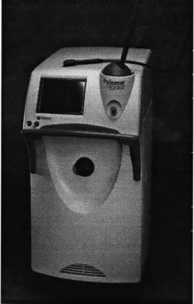
1.8.1 Palomar E2 0 00TM Ruby Laser System
The Palomar system is based on the work of Rox Anderson after years of research at the Massachusetts General Hospital Wellman Laboratories of Photomedicine, one of the world's leading medical research institutions. FDA approval for this system was received in July 1996. The 694nm-wavelength ruby laser light targets the melanin in the human tissue. The wavelength falls in the light spectrum that affords a desired
combination of absorption by melanin and deep penetration into the dermis. Melanin in the hair shaft, follicle and epidermis provides a chromophore for light absorption. The system is most suitable on patients with dark hair and light skin tone because of the competition of light absorption between hair and skin melanin. The epidermis contains eumelanin (responsible for brown/black coloration) through which the light must pass to reach the follicle. The goal of this method is to maximize follicle damage with minimum epidermal damage as shown in Figure 1.9. It is not recommended for Fitzpatrick IV skin types and above and for light hair tones.
I~M# j
The energy is delivered by a 10mm EpiWand® (Figure 1.10) hand piece through a thermally cooled tip. Most laser light is generated using either sub-micro-second pulses (Q-switched) or longer pulses. The E2000TM system uses a normal long-pulse to broaden the zone of thermal damage within and around the follicle. In general, longer localized laser pulses heat a larger volume and require greater fluence to achieve selective
follicular damage. 10 J/cm 2 (darkly pigmented individuals) to 50 J/cm 2 (fair-skinned) is the fluence range of the E20001' system.
The 3 msec pulse duration falls within the 'ideal' Thermal Relaxation Time (TRT) of the hair follicle (0.8 to 3.1 msec [Clark, 1998]) and on the lower threshold of the TRT of the epidermis (3 to 10 msecs [Grossman et al, 1996]). In addition to the standard 3msec pulse, the TwinPulseTM Mode system also has a unique pulse mode where two distinct pulses are emitted at 100 msecs. The pulse mode system coupled with the patented "Super Cooling" contact cooling hand piece (0 to -10 *C) delivers optimum energy to the reticular dermis while minimizing thermal injury to the epidermis. At this setting, it is possible to extract heat during the laser pulse while thermal confinement is maintained in the hair follicle. Heat is also conducted from the skin surface before and after each laser pulse by the cooling contact tip.
Sapphire Lens Tip Ot icalBeamFiber
A high refractive index sapphire prism/lens is used to provide a convergent beam
(approximately 20mm in focal length) at the skin surface and to increase beam coupling into the skin as compared with air as the external medium. Convergent beams increase irradiance at a given depth compared to collimated beams. The system also has a relatively large hexagonal spot diameter of 10mm to optimize light delivery. The
E2000TM system relies on a forceful compression of the skin to temporarily reduce blood flow and to compress the dermis significantly in order to reduce the distance between the surface and hair follicle. The system utilizes "Contact Sensing" technology, in which the laser energy is triggered by sensing optimal epidermal temperature, assisting the provider to achieve the most desirable long-term effect, while also maximizing laser safety. From experimental observations, the optimal temperature is usually achieved when the cooling
hand piece is firmly held against the skin surface at a force of a few pounds. Figure 1. 11 illustrates the compression of the sapphire lens tip of the EpiWand* on a cross section of the epidermis.
Sapphire Lens (Tip of EpiWand*)
Hair Follicle
Figure 1.11 Close-up illustration of sapphire lens pressing on skin cross section (Pal- Medical,Inc)
The treatment technique consists of preoperative shaving of the treatment site to prevent long and pigmented hairs that may lie on the skin surface from conducting light energy to the adjacent dermis. Treatment is performed by delivering light in a pattern of
laser pulses, adjacent to one another, while the contact cooling piece is firmly held against the skin before each pulse. The E2 0 00TM system's unparalleled potential speed is
particularly important in the treatment of large areas such as the back and legs. The system is, in theory, capable of treating a pair of female legs in four hours, or a man's back in about half that time. It could allow the surgeon to dramatically increase patient flow, which potentially lowers the cost per treatment. The problem is that the provider cannot manipulate the hand piece quickly enough to capitalize on the laser's inherent speed, while trying to maintain positional and application force accuracy.
To match the maximum pulse rate of the E2 0 00TM, the scanner must be capable of
operating at a 1 Hz hit rate. In other words, it must move from one location to the next in less than one second . Figure 1.12 shows the EpiWand® with an illustrated contact grid that simulates the contact zones on the skin. When located above the correct grid
position, the scanner will move the wand down in the Z-direction. When the force sensor detects a proper applied force, the scanner will hold position until the laser is fired. Immediately after contact firing, the scanner would retract the wand fully in the Z-axis before moving along the X-direction to the adjacent grid position. This would prevent the wand from dragging on the patient's skin. The scanner would raster the hand-piece along the X and Y directions, moving up and down the Z direction at each step, until the whole grid is completely treated. Each firing cycle should take place no longer than one second. In most cases, the laser hand-piece has to hold position for approximately 500 msecs before achieving optimum firing temperature. This leaves the scanner less than half a second to locate the next grid position.
The development and design of the automated precision scanner will be described in chapter two of this dissertation. Chapter three will cover the system modeling and control strategy of the scanner. Upon completion of the scanner, a series of tests were conducted to gauge its mechanical operating performance. The details of the experiments and a brief discussion of its performance are given in chapter four. Tests indicated that a velocity sensor that would provide actual velocity of the device relative to the skin, has to be developed. Chapter five describes the development of a series of velocity sensors suitable for this application. The dissertation is concluded in chapter six, which describes the clinical performance of the interfaced laser-scanner system on a patient . The final chapter also provides a discussion on the scanner and velocity system performance.
G A
F / B
/C
i~ fy D
Y
2 Development and Design of an Automated Precision Scanner
2.1 Functional Requirements and Constraints
There were a number of functional requirements that had to be met in the mechanical design of the scanner. These requirements shaped the final form of the machine. Potential cost of production was another major factor in the design process. The prototype machine had mass production potential so it was desired to keep cost down. As the prototype was one of a 'proof-of -concept' machine, more functional requirements were included to add versatility and help identify critical variables. Some of the functional requirements are listed below:
1) The scanner had to be fully automated.
2) Variable scanning patterns.
3) Scan range:
X&Y-direction: minimum 2 inches Z-direction: minimum inches 4) Repeatability:
X&Y-direction: 0.01 inches (250 microns) Z-direction: 0.004 inches (100 microns) 5) Cycle time:
Z-direction: 1/2 inch in 0.05 seconds X&Y-direction: 1/5 inches in 0.1 seconds
6) Force sensing range of 5 lbs.
The first requirement stipulated that there should be minimal human interference. This necessitated the use of a computer control system to automate and coordinate the electrical-mechanical structure.
The second requirement is driven by the need to have a flexible machine that can be used on various parts of the human body. The main applications would include the thighs, back and arms. The human arm has a relatively high curvature and aspect ratio. To accommodate this narrow area, the machine has to have a minimum scan area.
The third requirement is repeatability, and not accuracy of the X-Y direction. As most laser beams have a Gaussian distribution of energy density across its diameter, some overlaps in firing zones are recommended. This has the tendency to distribute the energy density more evenly across a scanned profile. The level of overlapping should be very repeatable to ensure consistency in treatment.
The fourth requirement satisfies one of the main motivations of an automated system, which is to increase throughput. Given that the scanner has approximately 400 msecs to position the laser hand-piece between successive firing for a 1 Hz repetition rate, the axes must be capable of high speeds. The total accumulated time from the design specification is 300msecs. This allocates ample time for the system to achieve steady state in all three axes before initiating fire. The requirement gives minimum speeds of 2 inch/sec for the X and Y stages and 10 inch/sec for the Z-stage. These velocity values are calculated using a rectangular velocity versus time profile. However,
almost all systems are driven by trapezoidal profiles and this would require a higher maximum velocity to maintain the same distance and time specifications.
The fifth requirement is important for the laser system to initiate. Optimal firing conditions are achieved when a proper force is exerted by the contact cooling hand-piece on the skin.
Finally, some form of communication between the laser system and scanner would increase the performance with both systems coordinating their operations. Pulses of 3 msecs trigger the E2000TM system. A quick sensing trigger mechanism on the
2.2 Design Issues
2.2.1 General Concepts
During the initial stage of scanner development, many concepts were created to address the functional requirements. The first concept (Figure 2.1) was a relatively large structure with 3 feet by 1-foot footprint. The main motivation behind this design was to fully automate the laser process over the length of a patient's leg and thigh with minimal
operator interference. For good clinical results, it is desired to bring the laser hand-piece perpendicularly to the skin surface. The system shown in Figure 2.1 has a curved axis to accommodate the curvature on the human body. However, a market study conducted by the sponsoring company concluded that as a first step towards automation, providers preferred a hand-held machine to a large fully automated system.
Laser hand-piece (silhouette)
urved Axis
Linear Stage
The second concept was a machine with an overall footprint of 5 inches by 5 inches. This concept was significantly smaller and could be handled by an operator. This necessitated a light and compact design. The operator would bring the machine to the
patient's body and hold it in place until the end of operation. The added advantages of such a system would be its low production cost and safety aspects. A small scan area has a relatively flat curvature making it possible to move away from the curved axis design. Figure 2.2 shows the design approach that was taken. The machine has two support handles for the operator. All three axes are packaged within the 150 cubic inches central volume.
Figure 2.2Handheld scanner concept
Further refinements of the second concept lead to a leaner design as shown in Figure 2.3. Different legs were designed for the final concept because of the need to have a proper mount on the skin surface. This design works especially well on highly curved surfaces. The mount has a four point contact configuration, a slight modification to the regular three point contact on kinematics joints. The fourth leg was added to increase
mounting orientation stability. The height of central casing was also reduced to cut down on weight. This further reduced the working volume available. The three axes are placed in a stacked configuration. Starting with the Y-stage at the bottom followed by the X-stage and the Z-X-stage at the top.
X
F .. .
.
.
2...o
a d ca2.2.2 Linear Stage Selection
The basic design of the three stages is quite straightforward. There is a wide selection of linear stages on the market based on different methods of actuation.
L D
Figure 2.1 BalIscrew driven actuator
The first and most conventional design of linear stage uses a ballscrew as the means of actuation. An illustration of such a ballscrew mechanism is given in Figure 2.1. The ball screw system is relatively simple and has good accuracy and repeatability. The limitation in its use is the 'critical speed' of the system. The critical speed occurs when the screw is turning at speeds nears its natural bending frequency. The system can then become resonant and the failure may follow.
The equation characterizing the critical speed for a given screw, as given in the Ballscrew and Actuators CO.(BSA),Catalog, is:
C = F x 4.76 x 10⁶X
Cs= Critical speed
L = Length between supports
F = End support factor (1.47 for one end fixed)
Based on a ballscrew length of 4.5 inches, the critical speed will be around
130,000 rpm. (using a lead screw of 3/8-inch diameter screw). With a normal ball screw
pitch of 0.15 inch per turn, the maximum speed of the carriage would therefore be limited to 250 inch/sec. This certainly meets our requirements. Ballscrew assemblies are very
streamlined because of their inline drive set-up. This suits applications where a high design aspect ratio is required, as in the case of the Z-axis.
The second option is the belt drive linear stage. A generic belt driven stage is shown in Figure 2.2. Belt drives have low stiffness due to the belt compliance and are only able to transmit low linear forces. This makes it undesirable as the choice of actuation for the Z-stage. However, the belt system is also cheaper and lighter.
W
R
Figure 2.2 Belt driven actuator
The final option considered is the rack and pinion drive (Figure 2.3). Its main feature as far as machines are concerned is that racks can be placed end to end to increase range. The drive's biggest drawbacks are that they generally exhibit backlash and do not provide a mechanical advantage the way a ballscrew system does. It is also difficult to
obtain the optimal transmission ratio and a speed reducer is often used with the motor that drives the pinion. This drive is usually used in systems that require long travel distance. The advantage of the rack and pinion system over the belt drive is that they can be made more compact. Due to the space constraints in our system and the simplicity in
design, the X and Y stages were based on the rack and pinion drive.
Motor
Pinion Rack
Figure 2.3Rack and pinion driven actuator
Other actuator alternatives such as friction drives and linear electric motors were not considered because of some drawbacks in application. Friction drives have low drive force capability and moderate stiffness and damping. Furthermore, they have minimal transmission gain and are very sensitive to the drive bar and capstan cleanliness.This makes maintainance an issue. However, friction drives have minimal backlash. The main disadvantage of linear motors is their high cost. They also develop less linear force than screw driven actuators and the inherent low damping complicates their control.
2.3 Design Concepts and Selection
After the drive systems were selected, the actuation of the stages needed to be determined. The application requires high-speed operation and moderate load capability. This necessitated the use of high power to size ratio actuators. Miniature DC brushed servomotors with integrated encoders and gearheads were chosen for all three axes. The control loop was closed using simple PID control based on the encoder feedback.
2.3.1 Z-Stage Design Alternatives and Concept Selection
Many concepts were generated for the Z-stage design during the initial stages of brainstorming. One of the major concerns in designing the Z-stage was its compactness. The entire assembly had to be packaged within a four inch cross sectional area and six inch height volume. The basic components of the assembly consisted of the force sensor, actuator, linear bearing, ballscrew and laser hand piece.
The force sensor required a minimum resolution of 0.05 lbs.-force and a range of up to five-pound force. Load cells were not considered because of their high cost. The positioning strategy for the Z- direction motions is relatively straightforward. Brushed
servomotor was chosen for the Z-stage. The motor came equipped with a magnetic encoder of 16 PPR before quadrature. When connected to a ballscrew of 0.15 lead, this
satisfied the 0.01 inches resolution stipulated in the functional requirements. Three concepts for force measurement were initially considered.
The first concept uses strain gauges to measure the applied force. Figure 2.7 shows a motor driving a ballscrew that is connected to the laser mount carriage through a cantilever arm. The laser mount carriage is constrained to move axially with a linear
bearing. A silhouette of the laser head is added to show its relative position in the whole assembly. The cantilever arm serves as a strain amplifier member for the strain gauges assembled in a Whetstone configuration. The assembly has few components and a simple design. However, preliminary calculations gave limited strain values in the cantilever member arm. Given the limited workspace, the length of the arm was restricted, resulting in lower strain values. This reduced the resolution of its force sensing capabilities.
Strain gauge (mounted on cantilevered arm)
Laser Mount Carriage
z
Y~x
Laser Head (Silhouette)
The second concept utilizes a cam mechanism to regulate the compression force exerted by a spring of known stiffness. The motor turns a shaft that is connected to a cam mechanism. The cam in turn drives a roller that is part of the laser mount carriage. The concept is illustrated in figure 2.8. The cam angle limits the travel of the laser mount carriage. The design is relatively more complicated and the force applied is implicitly controlled by the cam angle.
Motor
Spring
Roller
Z
Y X
The third concept had a linear variable displacement transformer (LVDT) measuring the displacement of a compression spring of known stiffness as the means of measuring force. In figure 2.9, the motor drives a ballscrew that is coupled to a
connector, which in turn drives the laser mount carriage via a compression spring. The motion of the laser mount carriage is guided by a linear stage. As the laser head makes contact with the skin, the axial force generated by the motor will create the spring compression force. The LVDT is capable of high-resolution measurement and replacing springs of different stiffness could vary the force range. This gives the system a high degree of versatility and was the design strategy that was chosen for the Z-stage.
Motor
LVDT
Connector Spring
Y X
2.3.2 Y-Stage Final Design
The scanner axes are stacked with the Y-axes on the bottom. The Y-axis has a high aspect ratio of 2:1 to keep the design compact. As such two linear bearings are required to provide a smooth linear motion , as shown in Figure 2.10.
The stage is driven through a 43:1 gearhead between the motor and the pinion drive to provide proper load matching. The use of gears with small motors allows high torque applications while maintaining a low weight. A DC Brushed servomotor with attached encoder with 16PPR before quadrature was chosen for the Y- stage. The achieved resolution was well within the functional requirements on the Y stage.
X-Stage Rack Backboard C ing X-Stage Linear Rail 7, %X
Y-Stage Ieft Pinion DC Brushed Motor Y-Stage Right
Linear Bearing Linear Bearing
Figure 2.10 Final Y-stage design Y
2.3.3 X-Stage Design
To obtain maximum power efficiency, the motor armature inertia and the load inertia reflected onto the motor were matched. Gear reduction of 43:1 came closest to optimizing this ratio. Similar to the Y-stage, a DC Brushed servomotor with attached encoder with 16PPR before quadrature was selected. Resolutions of 0.0002 inches could be easily achieved especially with the gearheads attached. This was well within the
functional requirements of the X- stage. The final X-stage design is shown in figure 2.11.
.. M... X-Stage DC Brushed . . Motor Y-Stage Frame Pinion Rack
X-Stage Linear Bearing
3 System Modeling and Control
A Digital Signal Processing (DSP) board drives all three axes, freeing up the host CPU for other task. A four axes PC-Bus Servo Motion Controller by Technology 80*
was chosen. PID position control strategies were used on all three axes. A trapezoidal acceleration profile was chosen over the S-curve profile. Trapezoidal profiles are faster of the two styles when moving an equivalent distance. This makes it preferable for quick moving action. S-curves generate softer acceleration and deceleration, thus lowering inertia torques.
3.1 System modeling
The three axes are placed in a stacked configuration with the Z-axis on the top and X-axis on the bottom. To simplify the analysis of the system dynamics of the scanner, it is assumed that the performance of the X and Y stages are identical.
3.1.1 X & Y Stages
Both stages were designed to carry a structural load of 5 lbs. (-2.5Kg) through a rack and pinion actuator. Aluminum pinions of pitch diameter 0.8324 inches were used and connected to the motor via 43:1 gearheads. The calculated total polar moment of inertia reflected at the motor is approximately 0.02 oz-in2 and is given by:
/ 2
J, = JM + Za (J i +MR2
Zb
Jt = Total polar moment of inertia
Jn = Inertia of motor
M = Mass of structure
R = Radius of pinion
a Gear reduction ratio; J = ijpw(d) (kgm2)
Zb 32
3.1.2 Z-Stage
The stage is driven by a stainless steel ballscrew of dimensions given in section 2.1 of this chapter. The mass of the entire Z- stage assembly is approximately 3
lbs. 0.09 oz-in2 is the inertia of the assembly that is reflected onto the motor. The
equation is given by:
J , = J ,nz + J ,c ,,, + M p )
27c
J= Total polar moment of inertia
J,n = Inertia of motor
Jscrew = Inertia of the ballscrew
M = Mass to be driven
3.1.3 DC-Motor schematics
Motor
V
Figure 3.1DC-motor schematic
R = Armature resistance L = Motor inductance
V = Voltage source
Vb = Back emf
Jt = Total inertia torque of plant reflected on motor
f
=FrictionMotor back emf constant
3.2 System control
DC servomotor positioning systems generally act as low pass filters and filter out
all frequencies above the bandwidth frequencies. The servo bandwidth will determine the limits of the systems performance and its dynamic range. The servo motion controller has a 16 bit Digital-To-Analog (DAC) command and outputs +/- 10 VDC. Three linear servo
amplifiers with gains of 2.4 were each used to drive the individual motors. This
facilitated the use of motors with low inductance and negligible electrical time constant
{
(L/R)-O1.
The frictional forces were also neglected because of the relatively low coefficient of friction in the miniature linear bearings used in all three stages. Figure 3.3 illustrates the basic PID controller strategy used on all axes.Figure 3.3 Block diagram of PID servo controller scheme
The third and fourth functional requirement stipulated that the scanner must be capable of rapid motion in all three axes with sufficient resolutions:
e Z-direction: 1/2 inches in 0.05 seconds with resolutions of 0.01 inches
* X&Y-direction: 1/5 inches in 0.1 seconds with resolutions of 0.0 1inches To achieve such performance specifications, proper gain values for the PID controller had to be obtained. The analysis can be simplified by working with a step response. For the all three axes, the maximum allowable design overshoot is 5%.
Given the rise time and maximum overshoot allowed in the system, the
proportional and derivative gain could be approximated using a PD controlled system. Once the Kp and Kd values have been obtained, the system response of a full PID will be analyzed to provide an optimum Ki value.
Determining the Kp and Kd-using a PD controller approximation
:X~~r e f Derivative +K~~~
X r ef K p R J s 4 K t K b .s - - b x u t
Desired Postion SuA1 Proportional Sur Transfer Fen Actual Position
Figure 3.4 Block diagram of PD servo controller
The closed loop transfer function is:
K , + Kds) CL = S2 +(1+KKd) S+KK where: K = KcKa K Ke Kt Kb RJ K, Kb
Comparing the denominator of this closed loop transfer function to that of a second order system:
(0 = K
1+ KKd
Transient response of a second order system: c(t) 1. 0.5 0 Allowable tolerance
Figure 3.5 Transient response of under-damped second order system (Ogata,1997)
The under-damped system response is given as:
C(t) = 1-e-C''(cosw 1-{ 2t+ sin c>, 1-{ 2t)
Maximum overshoot occurs at a peak time :
tM=
MP = C(t,) )-1
(3)
(4)
e J, (5)
The rise time (tr) is obtained from c(tr)=1
tr= 1 [cr-cos-'(()] (6)
Determining the Ki value from the full PID analysis.
Xref I Kd.s2+Kp.s+Ki K xout
Desired position Su Acua psiio
Sun PID Transfer Fon Actual position
Figure 3.6 Block diagram of PID servo controller
Given the design rise time(tr) and the allowable maximum overshoot (Mp) of the system, the proportional gain (Kp) and derivative gain (Kd) can be determined. However, such systems are susceptible to steady state errors. Adding an integral (Ki) will reduce such errors. Integral gains, however, raise the order of the system by one making it a third order system, which can become unstable beyond its critical gain (Kic) value. As Ki increases, the response becomes oscillatory and the settling time increases. The critical Ki can be found using Routh's stability array analysis. Matlab* simulations of the individual stages were conducted to determine the optimum tradeoff.
3.2.1 X & Y Axes
The X and Y axes have a design rise time of 0.1 seconds and maximum overshoot of 5%. From equations (4) and (5), the system has a damping ratio( ) of 0.69 and natural frequency (o n) of 32.85 Hz. Substituting these values into equations (1) and (2), the proportional gain (Kp) is determined to be approximately 100 and derivative gain (Kd) is
determined to be 1. A Ki value of 70 was chosen based on the overshoot response of the closed loop system. Routh's stability analysis on the closed loop PID system gives a critical Kic value of approximately 5100.
A Matlab* bode plot (Figure 3.7) of the control loop gives a servo bandwidth of 30 rad/s. The 0-100% rise time of the step response is approximately 0.1 sec and the
,0 0 -20 -40 -60 0
Servo Bandwidth ofX&Y-Stage
I i titi I -c ~~ it k t It it t I ' -60 I-100 10' 1C0
10
Frequency (rad/sec)Figure 3.7 Bode plot of the closed loop transfer function of the X & Y stages
S tep Resnprt ,sae.
Sj t e e-;'; p rZ;3 t"K:f -.StU:4
0.5 112
Time (sec.)
Figure 3.8 Step response of the X & Y stages
cc CD _0 0) U) .-0) 1.4 1 2 --CD E D.6 0.4 0.2 0 0 ik if I t li t: t t 1 5 tit ilt ki t: j j ;C
3.2.2 Z Axis
The Z-axis has a design rise time of 0.05 seconds and maximum overshoot of 5%. From equations (4) and (5), the system has a damping ratio( ) of 0.69 and natural
frequency ((on) of 66 Hz. Substituting these values into equations (1) and (2), the
proportional gain (Kp) is determined to be approximately 250 and derivative gain (Kd) is determined to be 3. A Ki value of 500 was chosen based on the overshoot response of the closed loop system and the disturbance rejection characteristics. Routh's stability analysis on the closed loop PID system gives a critical Kic value of approximately 26000.
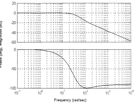
A Matlab® bode plot (Figure 3.9) of the control loop gives a servo bandwidth of 70 rad/s. The 0-100% rise time of the step response is 0.05 sec and the maximum
overshoot is approximately 4 %, as shown in Figure 3.10.
Servo Bandwidth of Z-Stage
20 - r-rrrr-, -- rrr-,-rm . r-rmrrr-r-rrrrrr
r
It I
i2 )2 3, 4
Frequency (rad/sec)
, Step Response... 1 4 1.2 e0.8 -0.2 0 ' 2 0.4 0 C 0.8 Time (sec.)