Publisher’s version / Version de l'éditeur:
Nanotechnology, 21, 3, pp. 1-7, 2010-01-22
READ THESE TERMS AND CONDITIONS CAREFULLY BEFORE USING THIS WEBSITE. https://nrc-publications.canada.ca/eng/copyright
Vous avez des questions? Nous pouvons vous aider. Pour communiquer directement avec un auteur, consultez la première page de la revue dans laquelle son article a été publié afin de trouver ses coordonnées. Si vous n’arrivez pas à les repérer, communiquez avec nous à [email protected].
Questions? Contact the NRC Publications Archive team at
[email protected]. If you wish to email the authors directly, please see the first page of the publication for their contact information.
NRC Publications Archive
Archives des publications du CNRC
This publication could be one of several versions: author’s original, accepted manuscript or the publisher’s version. / La version de cette publication peut être l’une des suivantes : la version prépublication de l’auteur, la version acceptée du manuscrit ou la version de l’éditeur.
For the publisher’s version, please access the DOI link below./ Pour consulter la version de l’éditeur, utilisez le lien DOI ci-dessous.
https://doi.org/10.1088/0957-4484/21/3/035603
Access and use of this website and the material on it are subject to the Terms and Conditions set forth at
Distinct termination morphologies for vertically aligned carbon
nanotube forests
Vinten, P.; Marshall, P.; Lefebvre, J.; Finnie, P.
https://publications-cnrc.canada.ca/fra/droits
L’accès à ce site Web et l’utilisation de son contenu sont assujettis aux conditions présentées dans le site LISEZ CES CONDITIONS ATTENTIVEMENT AVANT D’UTILISER CE SITE WEB.
NRC Publications Record / Notice d'Archives des publications de CNRC:
https://nrc-publications.canada.ca/eng/view/object/?id=efe8da87-28be-4848-b4a3-18a73876072d https://publications-cnrc.canada.ca/fra/voir/objet/?id=efe8da87-28be-4848-b4a3-18a73876072dNanotechnology 21 (2010) 035603 (7pp) doi:10.1088/0957-4484/21/3/035603
Distinct termination morphologies for
vertically aligned carbon nanotube forests
P Vinten
1,2, P Marshall
1, J Lefebvre
1and P Finnie
1,21Institute for Microstructural Sciences, National Research Council Canada, Building M-50,
1200 Montreal Road, Ottawa, ON, K1A 0R6, Canada
2Department of Physics, University of Ottawa, 150 Louis Pasteur, Ottawa, ON, K1N 6N5,
Canada
E-mail:[email protected]
Received 12 August 2009, in final form 13 November 2009 Published 7 December 2009
Online atstacks.iop.org/Nano/21/035603 Abstract
Vertically aligned carbon nanotube forests, including single-walled nanotubes, are imaged optically as they grow in situ from cobalt/alumina catalyst using water-assisted acetylene chemical vapor deposition. Three distinct termination morphologies are identified and
investigated optically and via scanning electron microscopy. Quantitative growth dynamics are extracted and show gradual deceleration and sudden termination of growth. The termination morphology is discussed in terms of the balance of forces within the forest. We speculate that sudden termination is a collective effect arising from an imbalance in these forces.
S Supplementary data are available fromstacks.iop.org/Nano/21/035603/mmedia
(Some figures in this article are in colour only in the electronic version)
1. Introduction
Initially, single-walled carbon nanotube (SWNT) yields were low, but in recent years growth via chemical vapor deposition (CVD) has advanced in terms of choice of catalyst and support, the use of more reactive carbon sources such as acetylene [1–4] and the use of an enhancer such as water vapor [5]. Millimeter tall forests of SWNTs and/or MWNTs (multi-walled carbon nanotubes) are now regularly synthesized [1,3,5–17] and research has shifted focus from how nanotube growth is initiated to the increasingly important question of how nanotube growth terminates [15, 18, 19]. Several reports demonstrate that nanotube forests grow at an initially rapid rate which drops off either gradually [7,20,21] or suddenly [15, 22, 23]. Because nanotube forests are attached to a substrate and grown in such abundance, process monitoring can be as simple as making in situ videos of forest growth [4, 21, 22,24, 25]. Due to the large number of nanotubes in close proximity within forests, mechanical stresses induced by interactions between nanotubes are very important factors contributing to their growth [10,18,24,26]. Here, we report the temperature dependence of the growth dynamics of nanotube forests obtained from in situ video monitoring of forests growing from ∼mm diameter thin film catalyst islands. We find that forest termination
is strongly temperature-dependent and that there are three morphologically distinct modes of forest termination. Rather than sudden termination just being a consequence of catalyst poisoning, we speculate that, for tall forests, termination is a collective effect caused by the buildup of strain on individual nanotubes and the balance between this strain and the forces present in the forest that keep the nanotubes attached to the substrate and to one another.
2. Experimental procedures
Forests were grown in a cold-walled CVD reactor (which provides excellent optical access to the sample [27–30]) operated at atmospheric pressure as described previously [21], with additional details given in other references [27, 28]. Forests were imaged in situ through a large glass window using a long focal length optical microscope and camera at an ∼5◦
glancing angle to the substrate.
The substrates were ∼0.4 cm2 square pieces of 0.5 mm
thick Si with 1 µm thermal SiO2. Layers of nominally
250 nm Al2O3 and 0.8 nm Co were deposited by e-beam
evaporation through a shadow mask to produce catalyst islands. For dynamics studies, masks with 700 µm diameter circles in a tightly packed hexagonal configuration were used. For
Nanotechnology 21 (2010) 035603 P Vinten et al
200
µm
200
µm
300 s
360 s
420 s
480 s
200
µm
0 s
60 s
120 s
180 s
180 s
240 s
300 s
360 s
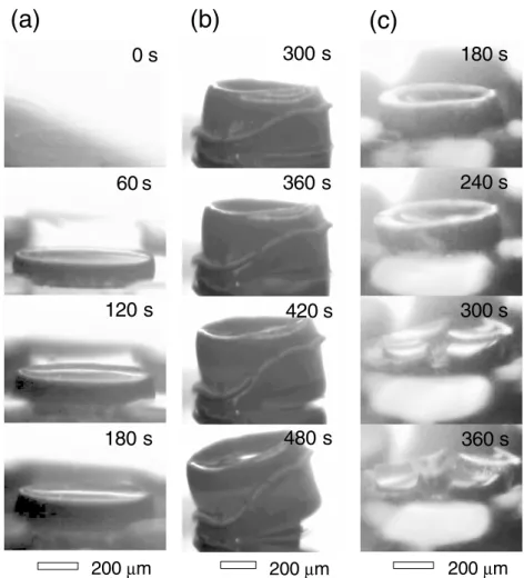
Figure 1.Frames from in situ videos (changed to black and white and contrast-enhanced) showing forests growing and terminating by: (a) stopping uniformly at 900◦C, (b) delaminating at 730◦C and (c) cracking at 720◦C. Original videos provided as supplementary material
(available atstacks.iop.org/Nano/21/035603/mmedia).
follow-up qualitative studies, we used a lower density pattern consisting of 800 µm diameter circles and a tightly packed pattern consisting of 100 µm diameter circles. Here, the carbon source was acetylene (C2H2) [2] and the growth was assisted
by water vapor [5], supplied by passing pure Ar through a bubbler.
Prior to growth the reactor was purged with pure Ar flowing at 2 l min−1 for 10 min. Samples were heated to
the growth temperature T (measured with a two-color infrared pyrometer) in Ar/H2 (98%/2%, 260 sccm). Water was then
introduced at 60 sccm for 5 min, keeping the total gas flow rate at 260 sccm. Dilute acetylene (Ar/C2H2, 99.9%/0.1%)
was then introduced at 180 sccm to initiate growth, while turning the Ar/H2 and Ar/H2O down to 60 and 20 sccm,
respectively. After the growth was determined to have halted, the chamber was purged with pure Ar and the sample was cooled for 5 min. Because the process and its end state are highly temperature-dependent, a series of otherwise identical samples were grown over a large range of temperatures; more than one sample was grown at some temperatures. After growth, forest morphologies were examined in detail by scanning electron microscopy (SEM). Raman spectra were acquired: acquisition parameters, spectra and derived
quantities are provided as supplementary material (figure S1, available atstacks.iop.org/Nano/21/035603/mmedia). D to G ratios decreased with T and the average number of radial breathing modes (RBMs) [21,31] increased with T from none at ∼700◦C to abundant at ∼850◦C. Intense RBMs provide
strong evidence for the presence of SWNTs, but do not exclude the possibility that MWNTs are also present in our forests. These Raman results are consistent with our previous report using ethanol as a carbon source [21].
3. Results and discussion
Frames from three different in situ videos are shown in figure 1. For clarity, the contrast has been enhanced and the images have been converted from color to black and white. The original color videos are provided as supplementary material (videos S1, S2, and S3 respectively available at
stacks.iop.org/Nano/21/035603/mmedia). Figure 1(a) shows a high temperature growth (900◦
C) from an initial circular catalyst island at time t = 0 s to a final forest at t = 180 s. Generally, at these higher temperatures, the terminal forest height Ht was relatively small. Forests simply grew
at a gradually decreasing rate until stopping rather abruptly 2
(a)
(b)
(c)
100 µm 100 µm 100 µm Figure 2.Post-growth SEM images taken at a ∼45◦angle: (a)uniformly terminated forest, (b) delaminated forest and (c) cracked forest. (a) and (b) are the same forests as in figure1.
at Ht. There was no abrupt change in the appearance of the
forest, and we classify this appearance as the first termination morphology: uniform. Upon termination, these forests have a relatively flat top surface and smooth sidewalls. At slightly lower temperatures, forests grew taller, but still grew relatively uneventfully. The uniform termination morphology was observed for all temperatures above ∼760◦
C, which reached heights up to 500 µm. An SEM image of this forest is shown in figure2(a).
At lower temperatures (730◦
C < T < 760◦
C) the termination was very different. Figure1(b) shows the second major termination morphology: delamination. As the forest (T = 730◦C) neared termination, the bottom of the forest
peeled off the substrate. Up until t = 300 s the forest looks similar to the uniform forest of figure1(a). Post-growth
delamination of forests has been reported to occur readily with simple processing [32,33], including the use of water [32]. Excessive water vapor exposure during growth has also been observed to cause delamination [14]. It has also been noted that forests tend to fall off the substrate easily [14], which is often the case here. Delamination of continuous films during growth has been previously reported [10]. We have occasionally seen forests completely delaminate. However, as shown here, the forest has only partially delaminated and terminates with some nanotubes still connected to the substrate. This is clearly visible at t = 480 s, for example. An SEM image of this forest is shown in figure2(b). The local delamination process appears to happen at or close to the time at which the entire forest stops growing. Other than delaminating, the forests are generally intact and have hardly changed otherwise.
Many samples show re-growth on the catalyst layer beneath the delaminated forest, but we have only ever observed a re-growth of a very short forest after delamination. More often, the remaining catalyst appears to be inactive or nearly so. Occasionally, only the outer nanotubes delaminate (partial delamination), which causes the base of the growing forest to narrow. On crowded samples, where it is difficult to see the base of the forest, we can sometimes infer that a delamination event has occurred because the top of the forest will appear to suddenly tilt just before termination, as seen in the delamination event presented here (see supplementary material video S2 available atstacks.iop.org/Nano/21/035603/mmedia). Follow-up SEM observation of tilted forests confirms that many of the tilting forests had indeed delaminated. Unpatterned (uniform catalyst) substrates sometimes show even more dramatic delamination effects, such as a forest grown on an unpatterned sample completely curling up onto itself (see supplementary material video S4 available at
stacks.iop.org/Nano/21/035603/mmedia).
Figure 1(c) shows the third termination morphology: cracking. Cracking of continuous nanotube forests has been previously observed by in situ optical imaging [24]. Here, up until t = 180 s the forest, grown at T = 720◦
C, looks similar to the uniform forest of figure1(a). This forest then suddenly splits into five wedge-shaped pieces which gradually bend outwards. Cracking occurs close to or at growth termination. These circular forests show remarkably symmetrical cracking patterns which can be threefold, fourfold, fivefold, and higher
N-fold; even circular cracking sometimes occurs. Cracking occurs at the lowest temperatures T < 730◦
C, although some samples show cracking and delamination simultaneously. There appears to be no abrupt transition between the two. It is notable that the cracked forests remain attached to the substrate.
Scanning electron microscope images (figure 2) show greater detail. Uniform forests, such as the example in figure 2(a), have relatively flat top surfaces and smooth sidewalls. Delaminated forests, such as the example in figure 2(b), often show small cracks on the top surface, in addition to delamination. Overall, the top surface appears smooth, but concave. In figure2(b), a small fraction of the nanotubes remain attached to the substrate on the left-hand side. The outer edge of the forest has also peeled away from
Nanotechnology 21 (2010) 035603 P Vinten et al
the bulk of the forest. This peeling started quite early, as can be seen from video S2 in the supplementary material (available atstacks.iop.org/Nano/21/035603/mmedia). We often observe such peeling effects. Figure 2(c) shows an SEM image of a cracked forest, grown at T = 720◦C. This forest remains
attached to the substrate. Many nanotubes can be seen bridging the cracks between the intact portions of the forest.
More insight into the morphological data can be obtained from the dynamical evolution of the forest height, which was extracted from the in situ videos. Figure3(a) shows the height of the forest H versus growth time t (circles), as sampled at 10 s intervals from the video in figure 1(a). From the start of forest growth to the sudden termination point, an excellent fit is obtained for an exponentially decaying initial growth rate that is consistent with a proposed growth equation [7]:
H (t) = βτ (1 − e−t/τ), where β is the initial growth rate and
τ is the characteristic time. However, the growth suddenly stops at a terminal height Ht(indicated by a horizontal line)
as previously reported from in situ observations [15,22] and inferred from ex situ data [11,19].
This general form is valid over the entire range of temperatures analyzed (figure 3(b)). Several growth temperatures are indicated by arrows pointing at the terminal height. Complete terminal height Ht versus temperature T
information can be found in figure4(a). Cracked forests (red dashed lines) do not show sudden termination in figure 3(b) because, once cracking began, it was too difficult to track the height of the forest quantitatively. Sudden termination was observed at a terminal time τtsoon after cracking began.
The difference between linear and exponential growth prior to sudden termination is rather small [15] and can easily be missed if sampling rates are too low. The slow growth rate decay, which, at least in the absence of water vapor, is thought to arise from carbon coatings that render seed nanoparticles inactive [34]. The sudden termination suggests that the terminal height Ht likely originates from a different
mechanism.
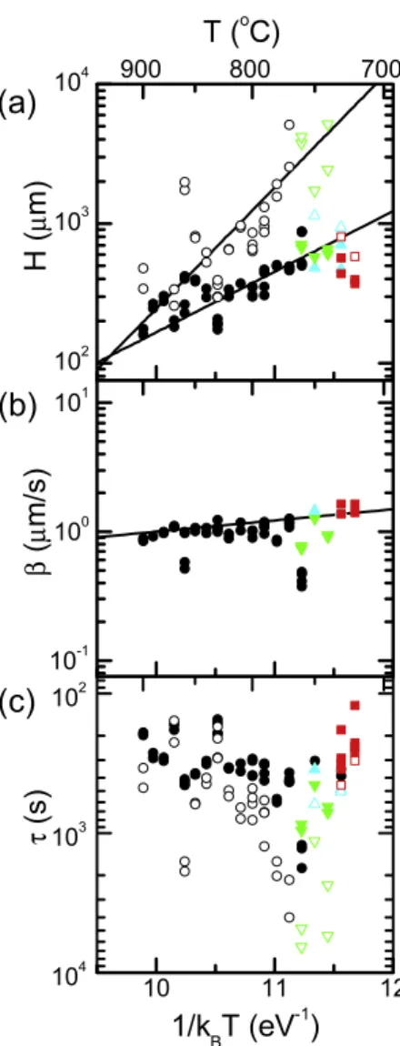
The temperature dependence of the extracted kinetic parameters is shown in figure 4. The solid black circles in figure4(a) show the observed terminal height of the forest Ht
versus inverse temperature 1/kBT, where kB is Boltzmann’s
constant. The terminal height Htfor the cracked forests (red
squares in figure4(a)) could not be directly measured because these forests generally self-destructed. In these cases, Htwas
calculated from the terminal time τtand the initial growth rate
β using the relation Ht=βτt. The open circles represent the
projected final height Hf, which is the height the forest would
have reached had the exponential decay dynamics continued and is given by Hf =βτ. All lines are linear fits that show a
characteristic energy [21], defined as the negative of the slope of a straight line on a plot of ln Y versus 1/kBT, where Y is
an arbitrary dataset. The actual forest height rapidly dropped to zero both below 720◦
C and above 900◦
C. Outside of this temperature range, a straight line approximation is not valid.
Ht decreases from ∼700 to ∼200 µm with increasing
T, with a characteristic energy of −1.0 ± 0.5 eV, which can be viewed as an effective ‘activation’ energy for sudden termination. The projected final heights Hf drop more rapidly
Figure 3.(a) Height H versus growth time t (circles) for a forest growing at 900◦C. Lines are an exponential fit (t < 220 s) and a
horizontal line (t > 220 s). Data extracted from video S1 (see supplementary material available at
stacks.iop.org/Nano/21/035603/mmedia), shown in figure1(a). (b) Experimental data for H versus t for all temperatures (∼50 growths, 720–900◦C). Termination morphology indicated by color:
uniform (black solid line), delamination (cyan dotted line), partial delamination (green dot-dash line) and cracking (red dashed line). Several growth temperatures indicated by arrows pointing at terminal height.
with temperature at a characteristic energy of −2.0 ± 0.5 eV, which is comparable to the scale found for ethanol CVD of nanotube forests at high temperature [21]. In this sense, the dynamics of forest growth from acetylene and ethanol are similar. The difference in the temperature dependence of the terminal height Ht and the projected final height Hf strongly
suggests that the sudden termination arises from a different mechanism than the gradual slowing of growth represented in the exponential decay dynamics. In other words, it is likely that sudden termination is not just a runaway process of gradual termination, but is rather more likely to be a process originating from a different mechanism entirely.
Figure 4.Inverse temperature (1/kBT) dependence of the logarithms
of kinetic parameters: (a) sudden termination height Ht(solid points)
and projected final heightHf(open points), (b) initial growth rate β and (c) sudden termination time τt(solid points) and characteristic
time τ (open points). Linear fits have characteristic energies: −1.0 ± 0.5 eV for Ht, −2.0 ± 0.5 eV forHfand −200 ± 200 meV
for β. Termination morphology indicated by color and shape: uniform (black circles), delamination (cyan upward triangles), partial delamination (green downward triangles) and cracking (red squares).
In addition to the height, other dynamical parameters were investigated. The initial growth rate β, as determined from the exponential fit (figure 4(b)), decreases with increasing
T with a characteristic energy of approximately −200 ± 200 meV. The small magnitude of the characteristic energy and the decreasing rate with temperature suggest that this energy corresponds to desorption (see, for example, Hudson [35]) or detachment of weakly adsorbed carbon-containing molecules. Small activation energies (of the order of meV) are expected for the desorption of physisorbed molecules because their primary interaction is through the weak van der Waals force. Increased desorption of carbon-containing molecules at high growth temperatures would lead to the observed decrease in the growth rate. Furthermore, 200 meV is the approximate desorption energy for small hydrocarbons from graphite, some metals, and oxides [36, 37]. We therefore conclude that
this slight temperature dependence likely originates from the molecular desorption of carbon that could have otherwise been incorporated into a nanotube. The sudden termination time τt (figure 4(c), closed circles) is similar to Ht and is largely
determined by the height of the forest in the sense that a slightly lower growth rate takes slightly longer to reach a critical height. There were some forests for which the only reliable dynamics data that could be measured was a direct measurement of τt
from the in situ videos due to extreme peeling of the outer layers. The characteristic time of the exponential growth rate decay τ , obtained by fitting, is also plotted (open circles).
We now turn to the possible physical mechanisms that may be responsible for the different termination morphologies as well as the sudden termination phenomenon. There is already one published model for sudden termination by Han et al [18] and we compare our data to this report first. Han et al proposed a model in which sudden termination is caused by the balance between the mechanical links between the tops of the nanotubes in the forest and the enthalpy of formation of the graphene lattice. In their model, the concave geometry often observed on the top surfaces of the forests originates from the halted growth of one nanotube which generates an outwardly propagating front of growth termination. However, our in situ observations show that the concave geometry of the top surface starts forming during the early stages of growth (see supplementary material video S2 available at stacks.iop.org/Nano/21/035603/mmedia). Han et al also predict that the center of curvature may lie anywhere across the top surface of the forest. However, we observe the center of curvature is essentially always the center of the top surface of the forest (see supplementary material figure S2 available atstacks.iop.org/Nano/21/035603/mmedia). Collective effects, such as those discussed by Han et al, may well be responsible for sudden termination: however, their specific model does not reproduce the data we observe.
The ‘normal’ configuration for a forest is to be bound to the substrate, with a top surface, side surfaces and a bottom interface. Nanotubes in a forest are far from the long and straight configuration that would minimize the internal strain energies for perfect nanotubes. Instead, they are bent, twisted, stretched and compressed through interactions with neighboring nanotubes, possibly due to slight differences in growth rate. Nanotubes in a forest are also far from the tightly packed configuration that would maximize their cohesion energies. Rather, strong adhesion energies bind the nanotubes to the substrate with boundary conditions set by the size of the catalyst island and the density of catalyst nanoparticles. The nanotubes are then arranged into small bundles that wander back and forth. The competition between strain, cohesion and adhesion leads to macroscopic morphological changes, and it is reasonable to conclude that this competition also leads to sudden growth termination. By observation of figure2, it is clear that these forests are indeed subjected to forces within that deform them.
Nanotube forests are never in an absolute minimum energy configuration and are thus instead in some metastable state in which changes are likely driven by the continuous buildup of strain. We suppose that the internal strain energy of the
Nanotechnology 21 (2010) 035603 P Vinten et al
nanotubes in the forest is balanced against the strong cohesion energies between nanotubes and adhesion energies between the nanotubes and the nanoparticles on the substrate. For the purpose of this discussion, we provide rough estimates for the magnitudes of these energies.
The adhesion energy can be roughly estimated by considering how the nanotube interacts with the substrate. In the base growth mode, a nanotube is first linked to itself along its length, then to the catalyst nanoparticle (Co), support (Al2O3) and substrate (Si:SiO2). Failure occurs at
the weakest point, which is at least as weak as the chemical bonds holding the tube together longitudinally. The bond dissociation energy of a C–C bond in a diatomic molecule is given in the Handbook of Chemistry and Physics [38] as 6.409 ± 0.160 eV. We use this value (6.4 eV) as an order-of-magnitude estimate for the energy of a C–C bond in a nanotube. For a 2 nm diameter zigzag SWNT (25, 0), there are 25 bonds through any slice perpendicular to the nanotube axis. Thus, we estimate an approximately 160 eV upper limit for the adhesion energy. Other points may be weaker, for example the nanotube–catalyst interface or the catalyst–substrate interface. Importantly, this energy is independent of nanotube length.
The cohesion energy is much weaker on a per carbon atom basis, but builds up quickly with increasing contact area. Using the binding energy between graphene sheets (∼80 meV/carbon atom [39]), it only takes ∼2000 carbon atoms for the van der Waals cohesion energy to equal the ∼160 eV adhesion energy. For graphene, this value corresponds to a ∼108 nm2 contact area (using
0.054 nm2/carbon atom as the surface density of graphene).
Longer nanotubes have more contacts with neighbors, so this energy is an increasing function of length. In contrast with graphene, nanotubes within a forest typically come into contact only once every µm and the contact lengths are short, thus the actual cohesion energies are weaker than calculated. Furthermore, the lattices of neighboring nanotubes in a bundle will not be in perfect registry. It may require several µm of forest height for the cohesion energy to match the adhesion energy.
Finally, the magnitude of the strain energy is estimated from the bending energy. Using the thin rod approximation (see, for example, Landau and Lifshitz [40]), the bending energy per unit length is given by Ebend/L = π8Y r4/R2,
where Y = 1 TPa is Young’s modulus, r = 1 nm is the nanotube radius and R = 350 nm is the bending radius. The bending radius corresponds to a nanotube constrained laterally to 100 nm and wandering with a 1 µm period. These length scales are estimated from typical high magnification SEM images (see supplementary material figure S3 available at
stacks.iop.org/Nano/21/035603/mmedia), which show that the nanotubes are organized into small bundles that wander back and forth. As a crude estimate, we suppose that the nanotubes typically come into contact with each other on the order of once every µm, with a spacing of approximately 100 nm between bundles. The estimated bending energy is 20 eV µm−1, which
means that 8 µm of forest height is sufficient to accumulate the equivalent of the ∼160 eV adhesion energy in bending strain energy.
For very short forests (H < 8 µm) the adhesion energy dominates over the cohesion and strain energies, but this is not the case for tall forests (H ≫ 8 µm). We expect there will be some height threshold above which adhesion becomes compromised by strain and cohesion. More detailed data concerning the nanotube wandering length scales and inter-nanotube contact areas would be required to accurately predict this height. Experimentally, the only morphology changes we observed occurred on forests taller than ∼100 µm.
Based on these competing processes, all with similar energies, we conclude that the delaminated forest in figure2(b) reduces its total energy by creating a new surface at its base. The loss of adhesion energy is compensated by relieving strain energy and possibly gaining cohesion energy. In a cracked forest, such as the forest shown in figure 2(c), the total energy is reduced by creating new side surfaces and space for local deformations to occur. The loss of cohesion energy is compensated by relieving strain energy, while there may be little or no change in the adhesion energy.
It is important to note that cracking provides good evidence for strain in nanotube forests. Indeed, among all three forces at play here, only strain is a force field with long range action. The macroscopic extent of the cracks in figure2(c) and their high degree of symmetry are both signatures of long range effects. This is in contrast with adhesion and cohesion forces which act more locally.
In materials science, sudden termination of continuous growth due to collective effects has long been recognized and is commonly observed for the growth of bulk crystals. A layer that is not exactly matched to the substrate’s elastic constants will grow continuously up to a critical thickness, above which dislocations will appear. In the Stranski–Krastanov growth mode (see, for example, Ayers [41]), strain and/or surface energies drive a transition from smooth continuous growth to rough island growth. It is plausible then that the sudden termination of nanotube forests could be an analogous effect.
Continuous growth of nanotube forests requires a balance between the internal nanotube strain energies, the adhesion energy attaching the nanotubes to the nanoparticles and substrate, and the cohesion energies between the nanotubes and bundles. The fact that sudden termination occurs very near to or at the same time as delamination and cracking suggests that termination may originate from the same root cause: the need for the forest to collectively accommodate the imbalance of the forces within. Sudden termination is then likely the result of the buildup of strain such that continued steady growth is no longer energetically favorable.
4. Conclusion
In summary, three main termination morphologies for CVD-grown nanotube forests have been observed and identified: uniform, delamination and cracking. Uniform termination is characterized by the sudden termination of the forest while maintaining its shape. Delamination is characterized by part or all of the forest detaching itself from the substrate as growth terminates, while remaining intact and retaining its shape. Cracking is characterized by a forest breaking apart as it terminates by splitting into several pieces. We speculate 6
that what determines the termination morphology is energy minimization, and that this is a collective effect of the many nanotubes in the forest. The buildup of strain in the forest is relaxed by the detachment of the forest from the substrate (delaminating) or the splitting apart of the forest (cracking). Likewise, the buildup of strain may make it energetically more favorable for the forest to stop growing, without going to the extreme of completely delaminating or cracking. The termination morphologies appear to be closely related to the phenomenon of sudden growth termination and give insights into the reasons for termination.
The goal of ‘infinitely’ tall SWNT forests should involve optimizing not just individual SWNT growth, but also optimizing collective effects. In situ methods provide valuable insights into the mechanisms responsible for nanotube forest growth and termination. Efforts to balance the energies present during growth, particularly through the use of in situ methods, appear to be a promising route to improving forest growth.
Acknowledgments
The authors thank the following IMS staff for their support: L Tay, H Tran, M Denhoff and J Fraser. PV was supported by OGS, NSERC, NRC-GSSSP and PF’s NSERC Discovery Grant.
References
[1] Eres G, Puretzky A A, Geohegan D B and Cui H 2004 Appl. Phys. Lett.841759
[2] Eres G, Kinkhabwala A A, Cui H, Geohegan D B, Puretzky A A and Lowndes D H 2005 J. Phys. Chem. B 10916684
[3] Zhang C, Pisana S, Wirth C T, Parvez A, Ducati C,
Hofmann S and Robertson J 2008 J. Diamond Relat. Mater. 171447
[4] Mattevi C et al 2008 J. Phys. Chem. C11212207
[5] Hata K, Futaba D N, Mizuno K, Namai T, Yumura M and Iijima S 2004 Science3061362
[6] Geohegan D B, Puretzky A A, Ivanov I N, Jesse S, Eres G and Howe J Y 2003 Appl. Phys. Lett.831851
[7] Futaba D N, Hata K, Yamada T, Mizuno K, Yumura M and Iijima S 2005 Phys. Rev. Lett.95056104
[8] Puretzky A A, Geohegan D B, Jesse S, Ivanov I N and Eres G 2005 Appl. Phys. A81223
[9] Li Q, Zhang X, DePaula R F, Zheng L, Zhao Y, Stan L, Holesinger T G, Arendt P N, Peterson D E and Zhu Y T 2006 Adv. Mater.183160
[10] Hart A J and Slocum A H 2006 J. Phys. Chem. B1108250
[11] Bronikowski M J 2007 J. Phys. Chem. C11117705
[12] Noda S, Hasegawa K, Sugime H, Kakehi K, Zhang Z, Maruyama S and Yamaguchi Y 2007 Japan. J. Appl. Phys. 46L399
[13] Yasuda S, Futaba D N, Yumura M, Iijima S and Hata K 2008 Appl. Phys. Lett.93143115
[14] Patole S P, Park J H, Lee T Y, Lee J H, Patole A S and Yoo J B 2008 Appl. Phys. Lett.93114101
[15] Meshot E R and Hart A J 2008 Appl. Phys. Lett.92113107
[16] Hasegawa K, Noda S, Sugime H, Kakehi K, Maruyama S and Yamaguchi Y 2008 J. Nanosci. Nanotechnol.86123
[17] Pint C L, Pheasant S T, Parra-Vasquez A N G, Horton C, Xu Y and Hauge R H 2009 J. Phys. Chem. C1134125
[18] Han J-H, Graff R A, Welch B, Marsh C P, Franks R and Strano M S 2008 ACS Nano253
[19] Stadermann M et al 2009 Nano Lett.9738
[20] Einarsson E, Murakami Y, Kadowaki M and Maruyama S 2008 Carbon46923
[21] Vinten P, Lefebvre J and Finnie P 2009 Chem. Phys. Lett. 469293
[22] Puretzky A A, Eres G, Rouleau C M, Ivanov I N and Geohegan D B 2008 Nanotechnology19055605
[23] Hasegawa K, Noda S and Yamaguchi Y 2008
Sudden-termination of millimeter-thick vertically aligned single-walled carbon nanotube growth evidenced by real-time monitoring NT08: 9th Int. Conf. on the Science and Applications of Nanotubestalk T 23
[24] Hart A J, van Laake L and Slocum A H 2007 Small3772
[25] Gunjishima I, Inoue T and Okamoto A 2007 Appl. Phys. Lett. 91193102
[26] Hart A J and Slocum A H 2006 Nano Lett.61254
[27] Finnie P, Bardwell J, Tsandev I, Tomlinson M, Beaulieu M, Fraser J and Lefebvre J 2004 J. Vac. Sci. Technol. A22747
[28] Finnie P, Li-Pook-Than A, Lefebvre J and Austing D G 2006 Carbon443199
[29] Chiashi S, Murakami Y, Miyauchi Y and Maruyama S 2004 Chem. Phys. Lett.38689
[30] Kaminska K, Lefebvre J, Austing D G and Finnie P 2007 Nanotechnology18165707
[31] Bond J, Lefebvre J, Austing D G, Tay L and Finnie P 2007 Nanotechnology18135603
[32] Murakami Y and Maruyama S 2006 Chem. Phys. Lett.422575
[33] Pint C L, Xu Y-Q, Pasquali M and Hauge R H 2008 ACS Nano 21871
[34] Yamada T, Maigne A, Yudasaka M, Mizuno K, Futaba D N, Yumura M, Iijima S and Hata K 2008 Nano Lett.84288
[35] Hudson J B 1992 Surface Science: An Introduction (New York: Wiley)
[36] Bruch L W, Diehl R D and Venables J A 2007 Rev. Mod. Phys. 791381
[37] Yang S, Ouyang L, Phillips J M and Ching W Y 2006 Phys. Rev.B73165407
[38] Luo Y-R 2009 Bond dissociation energies CRC Handbook of Chemistry and Physics(Internet Version 2009) 89th edn, ed D R Lide (Boca Raton, FL: CRC Press/Taylor and Francis)
[39] Charlier J-C, Gonze X and Michenaud J-P 1994 Europhys. Lett. 28403
[40] Landau L D and Lifshitz E M 1986 Theory of Elasticity 3rd edn (Oxford: Reed)
[41] Ayers J E 2007 Heteroepitaxy of Semiconductors (Boca Raton, FL: CRC Press)