HAL Id: tel-02619764
https://tel.archives-ouvertes.fr/tel-02619764
Submitted on 25 May 2020
HAL is a multi-disciplinary open access
archive for the deposit and dissemination of sci-entific research documents, whether they are pub-lished or not. The documents may come from teaching and research institutions in France or abroad, or from public or private research centers.
L’archive ouverte pluridisciplinaire HAL, est destinée au dépôt et à la diffusion de documents scientifiques de niveau recherche, publiés ou non, émanant des établissements d’enseignement et de recherche français ou étrangers, des laboratoires publics ou privés.
Dynamical spin injection and spin to charge current
conversion in oxide-based Rashba interfaces and
topological insulators
Paul Noel
To cite this version:
Paul Noel. Dynamical spin injection and spin to charge current conversion in oxide-based Rashba interfaces and topological insulators. Mesoscopic Systems and Quantum Hall Effect [cond-mat.mes-hall]. Université Grenoble Alpes, 2019. English. �NNT : 2019GREAY062�. �tel-02619764�
THÈSE
Pour obtenir le grade de
DOCTEUR DE LA COMMUNAUTE UNIVERSITE
GRENOBLE ALPES
Spécialité : Physique de la matière condensée Arrêté ministériel : 25 mai 2016
Présentée par
Paul NOËL
Thèse dirigée par Jean-Philippe ATTANÉ, UGA et codirigée par Laurent VILA, CEA
préparée au sein du Laboratoire Spintronique et Technologie
des Composants (SPINTEC)
et de l'École Doctorale de Physique de Grenoble
Dynamical spin injection and spin
to charge current conversion in
oxide-based Rashba interfaces
and topological insulators
Thèse soutenue publiquement le « 14/11/2019 », devant le jury composé de :
Mme, Stefania, PIZZINI
Directrice de recherche, Institut Néel, Présidente du jury
Mr, Michel, VIRET
Chercheur CEA Saclay, laboratoire SPEC, Rapporteur
Mr, Pietro, GAMBARDELLA
Professeur, ETH Zurich, Department of materials, Rapporteur
Mr, Abdelmadjid, ANANE
Enseignant-Chercheur, Université Paris-Sud, Examinateur
Mr, Dafiné, RAVELOSONA
Directeur de recherche, C2N, Examinateur
Mr, Manuel, BIBES
Table of contents
Introduction 6
1 Spin current to charge current interconversion by spin orbit coupling 12
1.1 Spin currents and charge currents . . . 12
1.1.1 Characteristic lengths . . . 12
1.1.2 Two currents model . . . 14
1.2 Spin Hall Effect . . . 16
1.2.1 Intrinsic Spin Hall Effect . . . 17
1.2.2 Extrinsic Spin Hall Effect . . . 18
1.3 Rashba-Edelstein Effect at surfaces and interfaces . . . 20
1.3.1 Rashba two dimensional electron gases and Topological surface states . . . . 20
1.3.2 Direct and inverse Rashba-Edelstein Effect . . . 23
2 Spin pumping by ferromagnetic resonance 29 2.1 Ferromagnetic Resonance . . . 29
2.1.1 Landau-Lifschitz-Gilbert equation . . . 29
2.1.2 Ferromagnetic resonance conditions . . . 31
2.2 FMR: a powerful magnetometry tool . . . 36
2.2.1 Broadband FMR: frequency dependence . . . 36
2.2.2 FMR in cavity: angular dependence at X-band . . . 38
2.3 Spin transfer via spin pumping by ferromagnetic resonance . . . 45
2.3.1 Origin of the spin injection . . . 46
2.3.2 Spin current expression . . . 48
2.3.3 Evaluation of spin charge interconversion efficiency . . . 51
2.4 Disentangling ISHE/IEE from spurious effects . . . 55
2.4.1 Spin pumping ISHE/IEE angular dependence . . . 55
2.4.2 Spin Rectification Effects . . . 56
2.4.3 Thermal effects? . . . 61
3 Spin Hall effect in heavy metals and Alloys 64 3.1 Spin Hall effect in pure metals: Pt, Ta and W . . . 64
3.1.1 Positive or negative spin hall angle? . . . 65
3.1.2 Stacking order dependence . . . 66
3.2 A possible thermal contribution? . . . 67
3.2.1 Lack of Universal method to evaluate the thermal related effects . . . 68
3.2.2 Spin Pumping experiment . . . 69
3.2.4 Differences in the timescale: further evidences . . . 71
3.3 Spin Hall Effect in Au based alloys . . . 75
3.3.1 Sample fabrication . . . 75
3.3.2 Methods . . . 76
3.3.3 Spin diffusion length and spin Hall angle in AuW . . . 77
3.3.4 Spin diffusion length and spin Hall angle in AuTa . . . 79
4 Rashba Edelstein effect at oxide heterointerfaces 82 4.1 A two dimensional electron gas at the surface of STO . . . 82
4.1.1 A 2DEG with appealing properties for spintronics . . . 83
4.1.2 STO\Al: no need of LAO . . . 84
4.1.3 STO 2DEG: a complex bandstructure . . . 87
4.2 Spin to charge conversion in STO\Al\Py structure . . . 90
4.2.1 Mapping to the bandstructure . . . 90
4.2.2 Role of the insulating barrier . . . 94
4.2.3 Spin to charge interconversion at room temperature . . . 96
4.3 Ferroelectricity in STO: non volatile switching of the IEE . . . 97
4.3.1 Ferroelectric STO? . . . 98
4.3.2 Remanent modulation of the spin to charge conversion . . . 101
4.3.3 Modulation of the 2DEG by ferroelectricity . . . 105
4.3.4 Possible memory and logic applications . . . 109
5 Edelstein effect in topological insulators 112 5.1 An efficient spin to charge conversion in strained HgTe . . . 112
5.1.1 Tensile strained HgTe on CdTe: a 3D topological insulator . . . 113
5.1.2 Sample preparation . . . 115
5.1.3 Spin to charge conversion: role of the HgCdTe barrier . . . 115
5.1.4 Spin to charge conversion: role of the HgTe thickness . . . 119
5.2 Sb2T e3: a sputtered deposited topological insulator material . . . 123
5.2.1 Sputtering: an industry compatible process . . . 123
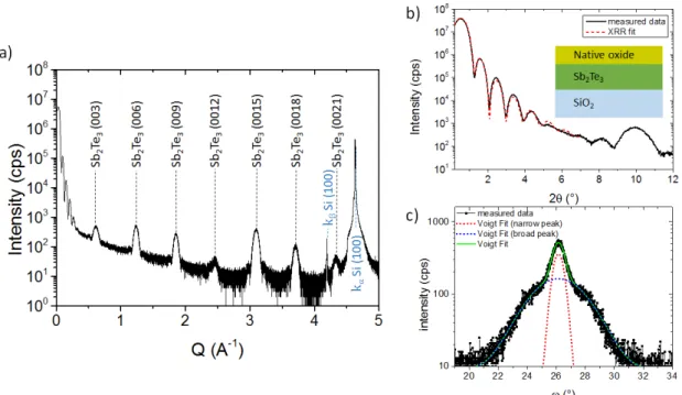
5.2.2 High quality thin films . . . 124
5.2.3 Magnetotransport: Weak Antilocalization . . . 127
5.2.4 Spin to charge interconversion . . . 131
Conclusion 134
Acknowledgment 139
Bibliography 142
A FMR cavity: Brucker MS5 loop gap 164
C Change of the magnetic properties of the ferromagnet with the applied power 170
D Gate voltage dependence of the ferromagnetic resonance lineshape in STO \CFB 176
Introduction
During the last fifty years the available processing power has evolved exponentially, thanks to the ag-gressive scaling down of transistors down to 10 nm or less1. This exponential downscaling has been
accompanied by an exponential decrease of the power consumption and of the manufacturing costs, as well as an increase of the available processing power, following what is known as Moore’s law2.
While still valid today, this exponential scaling is now approaching physical limits3. In order to
li-mit the power consumption of information and communication technology, that now represents more than 4% of the worldwide power consumption4, and to promote novel computing schemes for better
processing capabilities, new routes need to be explored. Beyond the scaling down of transistors and improved architectures, the field of spin-electronics or spintronics appears as a particularly appealing path in the quest of an electronic beyond Moore’s law.
Thanks to the intimate interaction of the electronic and magnetic structures with spin currents, spin-tronics allow novel ways to process information and store datas. The remanence associated with magnetization and the ability to switch it in hundreds of picoseconds makes it possible to obtain fast non-volatile devices. Moreover, it allows reducing the energy needed for information storage, as the data remain stored in absence of any power input. Spintronics also open novel routes for processing units, including logic in memory architectures or majority gate circuits5;6.
From Conventional spintronics
Although efforts on the understanding of various spin effects such as the Anomalous Hall Effect or the Anisotropic Magnetoresistance have been made since the 1950’s7 the birth of modern spintro-nics is usually associated with the independent discovery of the giant magnetoresistance (GMR) by the groups of Albert Fert and Peter Gründberg in 19888;9. This magnetoresistive effect appears in ferromagnetic\normal metal\ferromagnetic (FM\NM\FM) layers, and allows to obtain different levels of resistance depending on the relative magnetization direction of the two ferromagnetic layers10. Therefore, the resistance of this structure is sensitive to an external magnetic field. This effect permit-ted the development of a wide variety of sensors, such as read-heads for hard-disk drives. Those all metallic GMR devices were further replaced by magnetic tunnel junctions where the non magnetic metallic layer is an insulator11. In these junctions the tunnelling magnetoresistance (TMR) can reach hundreds of percent, compared to some dozens of percent for GMR devices12. Thanks to this higher change of resistance, magnetic tunnel junctions allow a better sensitivity and are now widely used as the reading head of Hard Drive disks13.
However, magnetic tunnel junctions are not only passive devices, operating as variable resistors sen-sitive to the magnetic field: they can also work as active devices. In 1996 Slonczewski14and Berger15
predicted the existence of the spin transfer torque (STT). This mechanism relies on the angular mo-mentum conservation: a flux of angular momo-mentum, known as a spin current, can be transfered from one ferromagnetic layer to the other, thus exerting a torque on the magnetization. This torque can lead the magnetization to precess16, it can induce domain wall motion17, or even lead to the switching of the ferromagnetic layer18. Using a ferromagnetic material as a source of spin current allows to write information by reversing the magnetization of a free layer, and it also allows to read the ma-gnetization direction using the TMR. This property has been used to develop a type of non-volatile magnetic random access memory (MRAM) known as spin transfer torque MRAM (STT-MRAM)19. These MRAMs are now reaching industrial scale production. They can be easily embedded in CMOS technology, are way faster than NAND Flash, and have a higher cyclability than phase change memo-ries. Moreover, when compared with SRAM and DRAM, they are comparable in terms of speed, but their non-volatility allows lowering the total power consumption20. In addition the STT can be used to induce magnetization precession. This leads to the development of magnetic oscillators for wireless communication, high frequency logic, or filters21.
Using a ferromagnetic layer has been the first method to obtain spin currents, allowing to modify the magnetization state of an adjacent layer using spin transfer torque. However, in recent years, an alternative way to manipulate spin currents has been proposed.
Towards spinorbitronics
An emerging field of spintronics, called spin-orbitronics, exploits the interplay between charge and spin currents enabled by the spin-orbit coupling (SOC) in non-magnetic systems. It is sometimes called “ spintronics without magnetic materials“, as the spin current source is not a ferromagnetic material anzmore. This promising way to obtain and detect spin currents has been first proposed by Dyakonov and Perel in 197122and was later experimentally demonstrated23;24;25;26;27. By harnessing
the spin orbit coupling, it is indeed possible to obtain spin-charge current interconversion through two effects known as the spin Hall effect (SHE) in the bulk of the material28 and the (Rashba-) Edelstein
Effect (EE) in surfaces and interfaces29. In both cases, thanks to the spin orbit coupling a flow of
current produces a transverse spin density, which can diffuse as a spin current in an adjacent material. The obtained spin current is transverse to the charge current and free of any charge current, which is why it is usually called a pure spin current. Conversely, it is possible to detect a charge current using the reciprocal (inverse) mechanisms, known as the Inverse Spin Hall and Inverse Edelstein Effects (ISHE and IEE). Both the SHE and EE can be used as a source of spin current or spin accumulation, and as a spin current detector.
In 2012, Michel Dyakonov, who first predicted the existence of the SHE, asked about the spin Hall Effect “What is it good for ? “(in terms of applications). His answer at that time could be summa-rized as “probably nothing“30. However, the spin currents originating from the SHE and EE have
been eventually found to be large enough to allow magnetization switching in SOC material\FM bilayers31. This effect is known as the spin orbit torque (SOT), a torque on the magnetization
reversal, the efforts of most of the spintronics community shifted towards these SOTs, with experi-ments such as current-induced magnetization switching32or magnetization oscillations33, and current-induced domain walls34 or Skyrmion motion35;36. Experiments on SOT have been first performed using Platinum31;37 and soon after high resistive phase of Ta and W32;38;39. Now a strong challenge lies in the understanding and the use of Rashba interfaces40;41;42 and topological insulators43;44 for future improvements in SOT devices.
Foreseen Spinorbitronics Applications
FIG. 1: Schematic representation of a a) Spin Transfer Torque MRAM and of a b) Spin Orbit Torque
MRAM.
Following the discovery of the spin orbit torques and the ability to switch magnetization with an in-plane current, a growing interest for Spin Orbit Torques Magnetic Random Access Memory (SOT-MRAM) emerged45. But other applications of the spin orbit interaction also appeared recently. For example THz emitter based on the ultra fast spin charge current conversion46 outperforms the best semiconductor THz emitters at a fraction of the cost. The reverse conversion, i.e., the ability to detect spin currents allows to obtain large output signals47and can be useful for spin-logic applications such as the recently proposed Magneto Electric Spin Orbit Logic (MESO logic) by Intel48. All these appli-cations rely on an highly efficient spin current to charge current interconversion.
The MRAM technology emerging today on the industrial scale is the spin transfer torque MRAM technology. Such a technology relies on the reading of the magnetization state by tunneling magne-toresistance and the writing by spin transfer torque. Nonetheless, it still suffers problems of density and reliability on the long term. As the writing path and the reading path are shared on a 2 terminal STT MRAM it is possible to switch the magnetization during the reading process. Moreover the insu-lating MgO barrier is particularly thin and can be damaged by the high current density going through it during the writing as seen in figure 1.a49;50. Such drawbacks are not present in the so called SOT MRAM. In such a 3-terminal MRAM the writing and reading path are separated, therefore the MgO barrier is not damaged during the writing process, and the thickness of the MgO can be higher. This
increases the device reliability45. Moreover, the total current density and power is lower than in their STT counterparts and the writing speed is faster37;51. The switching is performed by the spin accu-mulation due to either SHE or EE, the writing path is therefore composed of a spin to charge current conversion layer below the free magnetic layer as seen on figure 1.b. The fact that SOT MRAMs possess 3 terminals instead of 2 nonetheless limits the density, but it could be particularly useful in applications for which a high density is not needed but where reliability and high performances are importans, for instance for cache memory52. For now on, the main drawback of SOT MRAMs is that the switching is not field free, and that a small magnetic field is required to switch the magnetization, even though recent demonstrations of field free switching were performed38;53.
FIG. 2: Schematic representation of the MESO logic. a) Low-voltage-charge-based MESO
inter-connect with cascaded logic gates. Two inverters are chained together to form an interinter-connect. b) Operating mechanism for a magnetoelectric (ME) material. A ferromagnet is coupled via ex-change/strain to the magnetoelectric material and can be switched. c) Operating mechanism for spin-to-charge conversion using a high-SOC material (SO). A spin injection layer (SIL) is used where needed by the materials interfaces. Spins are injected from the ferromagnet (FM) and a charge cur-rent is generated in the SO layer by ISHE or IEE. Small red and blue arrows indicate up and down spins, injected from the magnet.
The spin orbit related conversion effects could also lead to the development of new spintronics de-vices, beyond MRAMs. For instance, in figure 2.a we can see the complete structure of two cascaded MESO logic devices. Each part is composed of a ferromagnetic material FM which can be switched by the magnetoelectric coupling with an adapted magnetoelectric element (ME), providing that a high enough voltage is applied. The magnetoelectric coupling between the ferromagnetic material (FM) and the ME element –typically a ferroelectric or piezoelectric material– allows to obtain the complete
switching of the ferromagnetic layer as depicted in figure 2.b. The second part of the device is com-posed of an IEE/ISHE material, possibly separated by a spacer spin injection layer (SIL) from the ferromagnet, and is the Spin Orbit part of the device (SO). Through efficient spin charge conversion the magnetization of the FM can therefore be read as seen in figure 2.c. If the output voltage is high enough it can lead to the magnetoelectric switching of the next connected Magnetoelectric layer, thus allowing the cascated gates to function. In that case, not only the efficient conversion is important but also the high resistivity. Regarding the fact that the main interest of this device for the Spin Orbit part is to obtain an output power as high as possible, and an output voltage as high as possible, this device would require a material with a high resistivity and a high conversion efficiency.
This beyond CMOS logic could possibly lead to the development of low power and memory-in logic devices. More importantly it is less sensitive to the resistivity of the interconnects: it is thus possible to use interconnects of high resistivity, which is not possible with conventional MOSFETs, thus limmi-ting the transistors density. If optimized, according to Intel, it should permit to achieve “progressive miniaturization, reduced switching energy, improved device interconnection and ultra low standby power“ compared to CMOS logic. However, there is still a long way to go to obtain materials that offers the possibility to have a competitive MESO logic.
Measure the spin to charge current conversion
Spin orbit coupling is therefore not anymore only a curiosity for physicists,it is emerging as an useful mechanism for electronics and optronics applications. But there is still the need to reach a better un-derstanding of the mechanisms at stake in the spin-charge conversion processes. These mechanisms are inherently set by the transport properties of the SOC material but are far from being completely explained.
There are several important parameters needed to obtain an efficient switching through SOT as well as a large spin signal detection. The first evident one is the conversion efficiency, and the spinorbitronics community is actively looking for materials possessing the highest possible conversion rates. In this context it is important to develop an accurate metrology tool of the spin–charge interconversion to de-tect conversion in the bulk of the material, and at surfaces and interfaces. Amongst the large number of possible techniques, such as for instance spin-torque ferromagnetic resonance (ST-FMR)54,
opti-cal detection55, electrical detection56;57, or second harmonic detection58, I choose during my PhD to
use the spin pumping by ferromagnetic resonance measurement (SP-FMR). The SP-FMR technique allows to evaluate the spin to charge current conversion efficiency in a large variety of materials while most other techniques are dedicated to the direct conversion from charge to spin such as ST-FMR and second harmonic. Moreover, using the SP-FMR technique instead of more conventional electri-cal detection techniques there is no need to nanopattern devices using costly E-beam lithography. The SP–FMR could also take advantage of previous developments in the experimental technique within the laboratory40;59;60;61;62
focus on the spin to charge interconversion mechanisms due to the spin-orbit interaction. In particular, we present the Spin Hall Effect, which occurs in the bulk of materials, and the Edelstein Effect, which occurs in interfaces and surfaces. In a second chapter we describe the spin pumping by ferromagnetic resonance technique, explaining why it is an useful and accurate metrology tool, and how to perform a good measurement. In the third chapter we describe the measurement of the spin to charge conversion using spin pumping in heavy metals and Au-based alloys that offer high conversion efficiencies. We also present a technique to eliminate possible spurious effects associated with temperature gradients. In the fourth chapter we will explore the possibility offered by the two-dimensional electron gas at the surface of SrT iO3 to tune conversion effects with a gate or spontaneous electric polarization,
and how this high conversion is intimately related to the bandstructure of SrT iO3. Finally, in the fifth
chapter, we will present some results on spin to charge current conversion in the topological insulators
HgT e and Sb2T e3, evidencing that this novel class of material shows large and promising conversion
Chapter 1
Spin current to charge current interconversion by
spin orbit coupling
Conventional spintronics and its applications rely on the possibility to inject spin currents using a fer-romagnetic layer and to detect it using a second one using either Giant Magnetoresistance (GMR)8;9 or Tunnel Magnetoresistance (TMR)11. Tunnel junctions composed of two ferromagnetic metals sepa-rated by an insulating MgO thin film, used as read-head in Hard Disk Drive, and in non-volatile Spin Transfer Torque MRAMs (STT-MRAMs)63 are at the heart of conventional spintronic applications. Such a spin injection and detection is permitted thanks to the spin polarization of the ferromagnetic material and to the spin-filtering of the MgO barrier. Ferromagnetic materials allowing efficient spin to charge current interconversion, leading to high TMR ratio, efficient STT-switching and high ther-mal stability are therefore needed for these applications.
Nonetheless, spin injection and detection is not limited to ferromagnetic materials, and an efficient spin to charge current interconversion can be obtained by harnessing the spin-orbit coupling. This can be done in a large variety of non-magnetic materials including heavy metals61;64;65, metals or oxides heterointerfaces40;66and the so-called topological insulators43;67;68. These materials could allow novel spintronics applications including Spin Orbit Torque-MRAM31;51;45which possess a higher reliability than their STT counterparts, the recently proposed Magneto-electric Spin Orbit Logic (MESO Logic) by Intel48, and optical applications in the THz range46.
In this chapter, we will first give a definition of the spin and charge currents, then we will describe the mechanisms involved in the spin to charge current interconversion through spin-orbit coupling, including the Spin Hall Effect and the Rashba Edelstein Effect. Finally we will describe the possible applications of spin-charge interconversion using Spin Orbit coupling.
1.1
Spin currents and charge currents
1.1.1
Characteristic lengths
For relatively high temperature above few Kelvins the motion of electrons in a medium is diffusive and is thus deeply related to scattering processes. These scattering mechanisms can be of various types, from scattering due to defects or impurities to scattering related to the electron-phonon interaction.The Drude model describes the transport of electron in a medium, the characteristic length (time) between two scattering events is known as the mean free path le(relaxation time τe). These two quantities can
be linked by the so-called Fermi velocity vF which is the velocity of electrons close to the Fermi level:
FIG. 1.1: Schematic representation of the electron and spin diffusions. One electron of a given spin
is subjected to several scattering events, eventually leading to a flip of the spin. The characteristic lengths are represented, the mean free path le, the spin flip length lsf and the spin diffusion length λs.
To obtain a complete description of electron motion, Drude model needs to be extended to account for the spin of the electron. For the sake of simplicity we will describe only the Elliot-Yafet mecha-nism69;70 that is valid in most transition metals as evidenced for Pt71. Similarly to the charge, during
these scattering events, it is also possible for the spin of the electron to change its direction. Some of the scattering events preserve the spins, and some do not preserve it. Therefore the diffusion mecha-nisms do not only affect the movement of the charge in the medium but also its spin. The characteristic length travelled between these changes of the spin direction is known as the spin flip length lsf. These
scattering events occur on average every τsf, the spin flip time. There is a loss of spin information due
to the change of the spin direction, and the transport of spin information is easier in material with a long lsf72. The spin flip time and spin flip length are linked via the Fermi velocity:
lsf = vFτsf (1.2)
The transport of the spin is thus governed by both the scattering of the electron and the spin flip. The spin diffusion length λsis the geometric mean of the spin flip length lsf and mean free path le:
λs = 1 √ 3vF √ τsfτe (1.3) the √1
3 prefactor takes into account the fact that the scattering mechanism is occurring in three
dimen-sions.
Depending on the nature of the main scattering process and of the properties of the material/impurities the spin diffusion length can vary consequently. For example, it is of several hundreds of nanometers in light metals such as Cu or Al73, while it is of only some nanometers in Pt or Ta61;74. Most of the materials with high spin orbit coupling, are known for their short spin diffusion length.
1.1.2
Two currents model
Let’s now define the spin and charge currents which are at the heart of spintronic mechanisms. The charge current density is defined as the flux of charges transferred through a surface S:
Jc=
e S
dN
dt (1.4)
with N the total number of charges. The spin up (down) current density can therefore be defined as a flux of spin up (down) angular momentum through a surface S. This leads to the following definition:
J↑(↓) = ℏ
S
dN↑(↓)
dt (1.5)
with N↑(↓) the number of charges of spin up (down). Strictly speaking, charge and spin currents have thus different units. In the following and in order to simplify the expressions, we will consider the spin current and charge current to be in the same unit, by multiplying the spin current by the Josephson constant 2eℏ. The charge current and spin current can thus be written as:
Charge current: Jc= J↑+ J↓ (1.6)
Spin current: Js = J↑ − J↓ (1.7)
FIG. 1.2: Schematic representation of a pure charge current, of a spin polarized current and of a pure
spin current.
The current can be either a pure charge current with no net flow of angular momentum, a polarized current when there are both a flow of charges and angular momentum and even a pure spin current if there is no net flow of charges but only of angular momentum as depicted in figure 1.2. Contrary to the charge current, that is defined by a direction and an intensity, the spin current should in general be written as a tensor including the current direction but also the spin direction30;75. This tensorial definition would nonetheless not be needed in the following of this manuscript as in most cases we will consider spins along a single direction.
It is to be noted that contrary to the charge current, the spin current is non-conservative. Indeed, the scattering events can modify the electron direction or its velocity but its charge is preserve. On the contrary, the electron spin information can be lost during spin-flip events. Therefore the motion of spins can not be described by the standard diffusion equation of electrons but by spin dependent diffusion equations, described using the Valet-Fert model76;77.
FIG. 1.3: Schematic representation of the geometry of the 1D Ferromagnetic (FM)/non magnetic
(NM) interface. Charge current is injected along the z direction. Electrochemical potential for each spin population and the weighted average one are shown.
Assuming a 1D Ferromagnetic/non magnetic interface along z as shown in figure 1.3 we have the following equations: 1 σ↑ ∂J↑ ∂z = 2 µs λ2 ↑ and 1 σ↓ ∂J↓ ∂z = 2 µs λ2 ↓ (1.8) J↑ = σ↑ e ∂µ↑ ∂z and J↓ = σ↓ e ∂µ↓ ∂z (1.9)
With e the electron charge, σ↑(↓) the electrical conductivity , µ↑(↓)the electrochemical potential λ↑(↓) the spin diffusion length for each spin population. µsis the weighted average of the electrochemical
potential of up and down spins governing the transport process. It is to be noted that in a non magne-tic material the spin diffusion length and spin conductivity of spin up and down should be the same, while they are different in a ferromagnetic material.
Combining equations 1.8 and 1.9 allows to determine the spin diffusion equation at a Ferromagnetic/non magnetic interface: ∂2µ s ∂z2 = µs λ2 s (1.10) ∂2(σ↑µ↑+ σ↓µ↓) ∂z2 = 0 (1.11)
Where λs is the spin diffusion length introduced previously, with λ12
s = 1 λ2 ↑ + 1 λ2
↓. Therefore the z
de-pendence of the spin current in the normal metal can be obtained by solving the differential equation 1.10 and 1.11. An example of the profile of the electrochemical potential is shown in figure 1.3 when charge current is injected along the z direction. Spin accumulation arises at the ferromagnetic/normal
metal interface and disappears over the spin diffusion length in the normal metal.
While charge current can be easily produced and detected in conventional electronics, it is not the case of spin currents. Production and detection of spin current with efficient interconversion process from spin to charge or charge to spin is therefore needed for energy efficient spintronics. By harnessing the spin orbit interaction, it is indeed possible to convert spin current to charge current and oppositely charge current to spin current. There are two known mechanisms: the Spin Hall Effect in the bulk of materials and the Rashba Edelstein Effect in the surfaces or interfaces. In the following we will describe these two mechanisms.
1.2
Spin Hall Effect
The Spin Hall effect is a spin orbit related effect that allows the charge to spin (direct effect) or spin to charge (inverse effect) current conversion, in absence of any ferromagnetic material. It was first described by Mikhail Dyakonov and Vladimir Perel in 197175;22, and the inverse Spin Hall Effect, the
conversion from spin current to charge current, was observed for the first time during the 70’s and 80’s in semiconductors by the group of Solomon in Ecole Polytechnique78and by the group of Fleisher at
the Ioffe Institute23;24.
FIG. 1.4: Schematic representation of the different Hall effects: a) Ordinary Hall Effect, b) Anomalous
Hall Effect and c) Spin Hall Effect.
The name of Spin Hall effect was introduced by Hirsch in 199928, by analogy to the ordinary Hall Effect. The direct spin Hall Effect was later measured in 2004 in semiconductor GaAs by Kerr rota-tion microscopy25, and was detected in metals only in 2006 in Aluminum27and Platinum26. Since its detection at room temperature and its possible applications in electronics it attracted a large interest. During the last decade a large number of spin Hall Effect materials including heavy metals57, alloys64,
and semiconductors79were discovered unravelling the existence of Spin Hall in a large variety of ma-terials...
While in the ordinary Hall effect an accumulation of charge is obtained transverse to the electric and magnetic field, in the spin Hall effect an accumulation of spins is obtained in a paramagnetic material in absence of magnetic field. The ordinary Hall effect is due to the deflection of carriers moving along an electric field by a magnetic field. This effect is well known to be caused by the Lorentz force, and leads to a charge accumulation resulting in a Hall voltage. But there is no net spin accumula-tion because the number of spin up and down is the same. The anomalous Hall effect is the result of spin-dependent deflection of carrier motion in a ferromagnetic material, which produces both a spin accumulation at the edges and a Hall voltage7. The spin Hall effect is also caused by spin-dependent deflection of carriers. As the number of deflected spin up and down is the same it produces no Hall voltage but gives rise to a spin accumulation80. All these mechanisms are associated with a non zero non-diagonal term of the resistivity tensor ρxy. In fig 1.4 we present these three different mechanisms.
The conversion efficiency for the spin to charge current interconversion, i.e. the figure of merit of a Spin Hall Effect material is called the Spin Hall Angle θSHE. It is a quantity without unity that links
the produced charge current to the injected spin current:
→ JcISHE= θSHE → Js× → σ (1.12)
where→σ is the spin polarization unit vector. In this formula the Josephson constant is already
accoun-ted in the expression of Js. The spin Hall angle can thus be defined as the non-diagonal part of the
resistivity tensor, the spin Hall resistivity, ρxy = ρSHE divided by the diagonal one ρxx. It is to be
noted that this definition is similar to the Anomalous Hall Angle:θSHE = ρSHEρxx
As this value is intimately related to the spin orbit interaction high efficiency is expected to occur in heavy metals such as Pt26, Ta32or W39, and alloys containing heavy metals impurity such as CuBi64,
AuW60or AuPt81.
Similarly to the case of AHE, the SHE has two different contributions, an intrinsic and an extrinsic one. The intrinsic contribution is related to the anomalous velocity of the carriers, and the extrinsic contribution is related to skew or side-jump scattering on impurities in presence of spin orbit coupling. In the following we will describe these mechanisms and their dependences on the resistivity of the SHE material.
1.2.1
Intrinsic Spin Hall Effect
The intrinsic contribution to the Spin Hall Effect exists even in absence of any impurity on which scattering could occur. This contribution is insensitive to the scattering time τ and originates from the band structure. The electrons obtain an anomalous contribution to their velocity (non-diagonal resistivity is non zero and spin dependent) related to the so-called Berry Curvature linking the band-structure to the anomalous velocity in presence of an electric field82;83. The fig 1.5.a presents the
intrinsic mechanism where electrons of different spins are deflected in two different directions in pre-sence of an electric field due to the anomalous velocity of electrons.
Platinum is a very well known material in the field of spinorbitronics and have a dominating intrinsic spin Hall Effect contribution. The expected scaling of the intrinsic Spin Hall Effect contribution with the resistivity is that the anomalous resistivity ρSHE is proportional to the square of the longitudinal
resistivity ρxx. It is to be noted that the spin Hall Angle in highly resistive Pt is thus higher than their
low resistivity counterparts, as shown by Sagasata et al71.
1.2.2
Extrinsic Spin Hall Effect
FIG. 1.5: Schematic representation of the different spin hall effect mechanisms a)intrinsic Spin Hall
Effect b) Side-jump scattering and c) Skew scattering.
The spin dependent deflection of carriers due to impurities has been vastly discussed (for more than 50 years) in order to understand the microscopic origin of the Anomalous Hall Effect (AHE) in fer-romagnetic metals and paramagnetic materials containing ferfer-romagnetic impurities84. Two possible
scattering mechanisms leading to the spin dependent deflections were identified, the skew and the side jump scattering contribution. They were first described by Smit (skew scattering)85 and Berger
(side-jump scattering)86as possible explanations to the non diagonal term of the resistivity in the case
of the AHE. The scattering events on impurities with spin orbit coupling are thus one of the possible origin of AHE in ferromagnets and SHE in paramagnets. By modifying the number of impurity it is then be possible to tune the spin Hall angle.
The skew scattering mechanism is related to the asymmetric scattering due to the spin orbit coupling on the impurity, leading to a change of the k vector direction before and after the scattering event. The fig 1.5.c presents the skew scattering mechanism, where electrons of different spins are deflected in two different directions with different k vectors in presence of impurities with strong spin-orbit coupling. Such a mechanisms of skew scattering for the Spin Hall Effect was first experimentally demonstrated by Niimi et al. in CuIr87and CuBi64and described by Levy and Fert88. The side-jump
scattering contribution is associated with a scattering of different nature. Close to the impurity with strong spin orbit coupling the electron is deflected in opposite direction when entering and leaving the proximity of the impurity due to the opposing electric field contribution. This leads the electron to preserve its k vector but to a deflection to the left (right) depending on its spin as seen in Fig1.5.b. The extrinsic side-jump mechanism has been only recently unambiguously observed in NiCu for AHE89 and AuTa for SHE90.
FIG. 1.6: Schematic representation of the a)skew and b) side jump scattering and link with number of
scattering events from geometry.
In a dilute alloy the resistivity increases linearly with the concentration of impurity due to the linear increase of the number of scattering events91. As shown in figure 1.6.a from simple geometry the spin Hall resistivity ρSHE is in the case of the skew scattering proportional to the number of scattering
events and thus to the longitudinal resistivity ρxx. This thus makes the spin Hall angle independent of
the resistivity, and thus to the alloying concentration as shown for example in CuIr87. The extrinsic side jump scattering contribution as can be seen in figure 1.6.b has a different resistivity dependence:
ρSHE is proportional to the square of the longitudinal resistivity, and the spin Hall Angle is thus
pro-portional to the resistivity ρxx90.
The scattering contributions are generally interesting as they allow to increase the spin hall angle in a cheap light metal material which can be mixed with an expensive heavy metal compound as Pt or Ir. Nonetheless large alloying concentration can not be reached for most of alloys and formation of clusters occur. Regarding all these contributions intrinsic or extrinsic, we obtain the following link between Spin Hall Angle and resistivity:
θSHE = (Cintrinsic+ Cside−jump)ρxx+ Cskew (1.13)
The sum of these different mechanisms would allow to increase the spin Hall Angle as a function of resistivity. It is to be noted that alloying with an impurity that allows to obtain a large side-jump contribution compared to a skew scattering one is more interesting for applications as it allows to
obtain large spin Hall angles with low resistivity and could increase the power efficiency for SOT for example. Nonetheless choosing the right impurity in order to obtain a large side jump contribution is not straightforward. The observation of the intrinsic contribution of Au in AuW alloys and of a large side-jump contribution in AuTa are described in Chapter III. Results about SHE in structures with Pt will also be presented.
1.3
Rashba-Edelstein Effect at surfaces and interfaces
The Rashba Edelstein effect has been first theoritically described in the eighties and early nine-ties92;93;29. It is also sometimes called the (Inverse) Spin Galvanic effect as it was first probed using
polarized radiations in the pioneering work of Ganichev et al. in 200294. Such an effect has been
wi-dely studied in semiconductor structures94;95;96, but it can also be observed in metallic heterostructures
such as Ag/Bi40 or oxide heterointerfaces such as STO/LAO66in the so-called Rashba interfaces and
also in surface states of Topological insulator43;67;68.
The very peculiar properties of surfaces and interfaces could lead to larger spin to charge conversion efficiencies than Spin Hall Effect and are associated with very specific band-structure properties. In the next part we will describe these specific properties and how they can be associated with a large conversion efficiency.
1.3.1
Rashba two dimensional electron gases and Topological surface states
The spin charge interconversion phenomenon by Spin Hall Effect occurs in the bulk of the material. Nonetheless the conversion can also occur in surface states or in interface states of some materials, as long as they possess some specific properties. It is well known that surfaces of solids or interfaces of heterostructures behave differently from the bulk in various ways because the surrounding environ-ment of the atom is different from one in the volume.
In the bulk of a solid the free electron is moving in a periodic solid with both inversion symmetry
E(↑ , →k ) = E(↑ ,− →k ) and time reversal symmetry E(↑ , →k ) = E(↓ ,− →k ). This thus leads to the
spin degeneracy E(↑ ,→k ) = E(↓ ,→k ), where↑ (↓) are the spin up (down) and→k the k-vector. In that
case the dispersion curve of free electrons of effective mass m∗is spin degenerate E(k) =ℏ2k2/2m∗
as can be seen in figure 1.8.a The experimentally observed dispersion of free electrons by means of Angle-resolved photoemission spectroscopy (ARPES) in light metals such as Copper97 correspond
well to this description.
However when the inversion symmetry is broken either by a surface or an interface the spin dege-neracy is lifted, which leads to some change in the electron dispersion. This was first described by Yurii Bychkov and Emmanuel Rashba and is thus called the Bychkov-Rashba or Rashba effect92. It
is to be noted that in crystals with lack of inversion symmetry, in the bulk of polar or ferroelectric materials the spin degeneracy can also be lifted . This is the case of GeTe99 or BiTeI100, though in
FIG. 1.7: Schematic representation of nearly free carriers with or without Rashba spin splitting. In a)
Bands with spin degeneracy typical for bulk of materials without breaking of inversion symmetry or interfaces with lack of spin orbit coupling. b) Bands with a spin degeneracy lifted by a strong Rashba interaction at a Rashba interface with spin orbit coupling. c) Nearly free electron dispersion curve of Cu(111) measured by ARPES. Because of the small spin orbit coupling in Cu (Z=29) spin splitting is not visible d) Dispersion of Bi/Ag interface measured by means of ARPES with giant spin splitting of the bands. Figure c) and d) are extracted from reference97and98
inversion symmetry breaking an electron moving in a surface or interface experiences an electric field
→
Ez perpendicular to the surface and an effective magnetic field →
Bef f therefore a splitting of the band
happen. Such an effect can be described by the Rashba Hamiltonian HR:
HR= αR( →
ez × →
k ).S (1.14)
where the Rashba constant αR describes the strength of the Rashba interaction. →
ez is the unit vector
oriented perpendicular to the surface, →k is the electron momentum and S is the Pauli matrices that
gives the spin of the electron. αR is proportionnal to λEz where λ is the spin orbit constant. In
ab-sence of Rashba field (αR= 0), bands of opposite spins are degenerate as schematized in figure 1.8.a.
This is the case for the surface of light metals as Cu, where despite the existence of broken inversion symmetry at the surface the splitting is weak due to the lack of strong spin orbit coupling.
In presence of broken inversion symmetry (at interfaces or surfaces) and of a strong spin orbit inter-action the Rashba interinter-action is sizable. This thus gives rise to a splitting of bands of different spins that is larger when the αR value is larger, as can be seen in figure 1.8.b The dispersion equation for
such bands is92:
E±(k) = ℏ
2k2
2m∗ ± αRk (1.15)
As experimentally observed by ARPES in figure 1.8.d. a large splitting of the bands can be obtained at the Silver-Bismuth interface98, where a large Rashba parameter is obtained. This is due to both a
large spin orbit coupling in Bismuth and electric field due to the interface. More importantly, as can be seen from the Rashba Hamiltonian it is clear that the spin S, the k-vector →k and the
perpendicu-lar to the planee→z are all perpendicular to each other to have a maximal contribution of the Rashba
Hamiltonian. This leads the spin to lie in the plane perpendicular to →k , a phenomenom know as the
spin momentum locking.
FIG. 1.8: Topological surface States. a) Schematic representation of the dispersion relation of
Topological surface states with a Dirac cone exhibiting the spin momentum locking. b) Angle Resolved photoemission spectroscopy of Sb2T e3, linear dispersion of in-gap states from reference101.
Beyond Rashba interfaces, surfaces of 3D Topological insulators are attracting a growing interest in spintronics. Topological insulators are a recently discovered class of materials that possess a bulk band gap (insulators) but conductive surfaces knonw as topological surface states. They are named 3D topological insulators because they are insulating in the bulk (3D) but conductive in the surface. They were first described in 2007 by Fu, Kane and Mele102;103, and since then a large number of topological insulators or related materials as Weyl Semimetals or Topological Semimetals have been discovered. This includes BiSb104, Bi2Se3105, Bi2T e3106, Sb2T e3107, but also HgT e108 or α− Sn109. In fact
this kind of material is not so uncommon and according to recent calculations 11% of all material in nature are topological insulators110.
The topological surface states of TIs are Dirac like states with spin momentum locking111. These surface states can be described by the following Hamiltonian:
HR=±ℏvf( →
ez × →
k ).S (1.16)
With vf the Fermi velocity. The sign± describe the change of chirality below and above the Dirac
point. Schematics of the Energy dispersion of the surface states is shown in figure 1.9.a and an ARPES measurement of Sb2T e3101with the Dirac-like dispersion can be seen in figure 1.9.b. Due to the large
number of different systems the complete description of the bandstructure of a Topological insulator is complex and out of the scope of this manuscript112.
When the Fermi level lies in the gap and cross only the topological surface states the Fermi Contour resembles the one of Rashba interfaces. Spin to charge current interconversion can thus be described similarly in both Topological Insulators and Rashba interfaces. We would like to mention here that as topological insulators are materials with high spin orbit coupling the SHE could occur in their bulk when the fermi level is crossing a bulk band. Moreover Rashba splitting can also occur at their surfaces as is observed in Bi2Se3113. In the following we would not focus anymore on the Rashba
Hamiltonian and on the topological surface states but on how this specific bandstructure and more particularly spin momentum locking can be harnessed to obtain spin charge interconversion with possibly high efficiency.
1.3.2
Direct and inverse Rashba-Edelstein Effect
Let us now focus on what happens when charge current is injected in these materials. Due to the strong similarities between the bandstructures of Rashba interfaces and topological insulators we will present both of them simultaneously. Figure 1.9.a shows the Fermi surface of a Rashba interface in absence of any current, with two Fermi contours of opposite chiralities one clockwise and the other one counter clockwise. Figure 1.9.c shows the Fermi surface of the surface state of a Topological insulator, which is indeed very similar to the one of Rashba except that there is only one chirality.
When a current density →j is injected in the plane of the sample along -x, there is an electric field
in the same direction with →j = σ E with σ the electrical conductivity. Therefore a Coulomb force→
→
FCoul acts on the electron in the material with →
FCoul= q →
E where q is the charge of the carrier. By
applying Newton’s second law FCoul→ = d →
p
dt where →
p is the momentum, and as →p = ℏ →k injecting a
charge current during a time ∆t induces a shift of the Fermi surface. This shift∆k of the contour is given by:→
→
∆k= ∆tq
→
j
σℏ (1.17)
FIG. 1.9: Schematic representation of the Direct Edelstein Effect: a) Fermi contours in a Rashba
interface with no charge current b) Fermi Contours in a Rashba interface. When a charge current is injected along -x the Fermi contour is shifted. This gives rise to a spin accumulation, the two contours of opposite helicities partially compensating each others c) Fermi Contour in a Topological surface State with no charge current d) Fermi Contour in a Topological Surface State when a charge current is injected along -x the contour is shifted which leads to a spin accumulation.
is not affecting the Fermi contour anymore, as the momentum of the electron is randomized114. As τ is short typically of the order of fs in metals and up to ps in semiconductors, in the permanent regime:
→
∆k= τ q
→
j
σℏ (1.18)
This shift is independent on→k and thus leads to a rigid shift of the Fermi contour, as depicted in figure
1.9.d. for the topological surface states. When two contour are presen,t as in the case of Rashba in-terfaces, both contours are shifted (cf 1.9.b).This more complex case has been fully treated by Miron and Gambardella115. In the case presented in figure 1.10, the carriers are electron (q = -e) as the shift is opposite to the direction of the current. Due to this shift of the Fermi contour ∆k there is a spin→ accumulation that arises in both the Rashba and Topological insulator case. In the case of Rashba in-terfaces, as there are two contours of opposite helicities, the total spin accumulation is reduced. They might also have a different relaxation time τ .
If this spin accumulation can relax to an adjacent material, a spin current will flow towards the adjacent material. This effect is known as the direct Edelstein effect, that was first predicted by V.M. Edelstein in 199029. The conversion from a 2D charge current to a 3D spin current is defined a the inverse of a length qEE116with: qEE = Js3D J2D c (1.19)
The ratio between the escaping 3D spin current and the injected 2D charge current. This value needs to be maximized to obtain the largest conversion possible.
FIG. 1.10: Schematic representation of the Inverse Edelstein Effect: a) Fermi Contours in a Rashba
interface with no spin current injection. b) Fermi Contours in a Rashba interface. When a spin current is injected along z with the spin direction along y the Fermi contour is shifted giving rise to a non-zero ∆k and thus a charge current. The two contours of opposite helicities partially compensate each others. c) Fermi Contour in a Topological surface State with no spin current injection d) Fermi Contour in a Topological Surface State when a spin current is injected along z with spin along y. The Fermi contour is shifted, giving rise to a non-zero ∆k, and thus to a charge current.
Let us now focus on the reciprocal effect, the inverse Edelstein effect. In figure 1.10.a and c, the Fermi Surface of a Rashba interface and of a Topological insulator are represented in absence of spin current. When a spin current is injected perpendicular to the surface, due to an out of equilibrium spin density
< δS > the Fermi surface is shifted by∆k. Due to this shift and with equation (1.17) a charge current→ is obtained as shown in figure 1.10.b and d. A three dimensional spin current injected perpendicular to the surface is converted into a two dimensional charge current, and spin to charge conversion is obtained. The conversion efficiency is defined as a length, the inverse Edelstein length λIEE40:
λIEE = J2D c J3D s (1.20)
The ratio between the resulting 2D charge current to the injected 3D spin current.
Calculation of Spin to charge conversion efficiency: case of topological insulator
Calculation of the inverse Edelstein length in a topological insulator has been done by Fert and Zhang by using the spinor Boltzmann equation117. In this model they showed that assuming no effect due to
the interface λIEE = vFτ = lewhich means that the inverse Edelstein length should be equal to the
mean free path. The sign of λIEE would depend on the type of carrier involved and the chirality of
the contour. In this part we propose to calculate this from the shift of the Fermi contour with respect to the out of equilibrium spin density
For a single contour as in the case of topological surface states. The out of equilibrium spin density is equal to the total number of spins injected during the relaxation time τ :
< δS >= τ J
3D
S
q (1.21)
For small shifts of the contour ∆k ≪ kF where kF is the k-vector at equilibrium, the total spin density
corresponds to the surface occupied by electrons of a given spin, and can be written as:
< δS >≈ 2πkF∆k (1.22)
As shown previously in equation (1.17), the link between ∆k and charge current Jc2D leads to:
< δS >=±kFτ eJ
2D
c
σℏ (1.23)
The sign depends on the chirality of the contour (clockwise or counter-clockwise) and the kind of carrier involved (electrons or holes). In the following, and for the sake of simplicity we will consider the absolute value of < δS >. The expression of the Fermi wave vector is given by kF = evFτ /µℏ
and the one of conductivity by σ = neµ118. Moreover in a 2DEG system the carrier density n is linked to the Fermi wave vector n = 2πk2F, we obtain:
< δS >= J
2D
c
qvF
(1.24)
Combining equation 1.20, 1.21 and 1.24 we obtain the expression of the inverse Edelstein length for a unique Fermi contour, i.e. in the case of a topological insulator:
λIEE = vFτ = le (1.25)
Calculation of Spin to charge conversion efficiency: case of Rashba interface
In presence of two contour with opposite helicities in Rashba interfaces, the conversion is partially compensated by the contour of opposite chirality. The spin density of the majority contour δS+ and
of the minority contour δS− needs to be accounted for the evaluation of the total spin density: <
δS >= δS+ + δS− as well as the total current production Jc2D = J+ + J−. These two contours
have different relaxation time τ±, and Fermi wavevector kF±, but the same Fermi velocity in the free
electron approximation. This thus make the calculation similar but longer than in the case of a single contour. By using results from Gambardella and Miron115and also of Rojas-Sanchez et.al40, one can obtain at the first order in αR:
kF +− kF−= 2m∗ ℏ2 αR δS± =± m ∗ 2eℏkF± J± Jc2D= qαR ℏ < δS > (1.26)
Using the previous equations and equation 1.20 and 1.21, the inverse Edelstein length in the case of a Rashba interface is thus of :
λIEE =
αRτ
ℏ (1.27)
Its sign will also depends on the chirality of the contour and type of carriers at the Fermi level.
It is noteworthy that in both cases, the larger the electron scattering time τ , the larger the conversion efficiency. Materials which offer long scattering time with small Spin Orbit Coupling, and thus small Rashba spin splitting, offers possibly larger conversion efficiencies than those with a large Spin Orbit but a short relaxation time. It is indeed the case as Ag/Bi, an interface with one of the largest Rashba constant but a short electron relaxation time, gives a smaller conversion efficiency than the STO/LAO system, which possess a small Rashba constant but a particularly long relaxation time at low tempe-rature66.
Also, the direct contact with a metal might be detrimental for the conversion because of the possible relaxation channel towards the highly conductive material. It was shown recently that the transmis-sion rate across the interface gives a non-zero contribution to the transport relaxation, and thus plays a major role in the conversion efficiency. A choice of a proper interface is therefore needed to improve the conversion efficiency119. The fact that the conversion efficiency is sensitive to the mean free path emphasize that the Edelstein effect has a different origin than the intrinsic Spin Hall Effect, which is connected to the anomalous velocity and often unsensitive to the relaxation time82.
To compare IEE and ISHE efficiency it is needed to find a similar figure of merit. Indeed, the conver-sion through ISHE converts a 3D spin current into a 3D charge current so that the converconver-sion efficiency
θSHE is dimensionless. In the case of IEE, the conversion is from a 3D spin current, to a 2D charge
current. Thus the conversion efficiency is a length λIEE, as depicted in figure 1.12. As in a SHE
FIG. 1.11: a) Conversion of a 3D spin current in a 3D charge current in an ISHE material b)
Conversion of a 3D spin current in a 2D charge current charge current in an IEE material.
diffusion length λs, the equivalent 2D charge current would be Jc2D = λsJc3D. In that case the
effec-tive conversion length for SHE material λ∗ is the product of the spin hall angle by the spin diffusion length:
λ∗ = θSHEλs (1.28)
Materials in which Spin Hall Effect or Edelstein Effect occur can possibly allow increased spin charge interconversion efficiency. This could lead to novel spinorbitronics applications as novel magnetic RAM or beyond CMOS logic devices as presented in the introduction.
Spin to charge interconversion by harnessing the spin orbit interaction can be obtained by various means, as explained in this chapter it can be obtained through spin Hall Effect or Edelstein Effect in a large variety of materials. It also extends the field of spintronics beyond ferromagnetic materials. This conversion is intimately related to the bandstructure, impurity nature, spin orbit strength...etc. For applications and also to understand the deep physics of the spin charge interconversion a method of accurate evaluation of this conversion is needed. In the next chapter we will describe how spin pumping by ferromagnetic resonance allows to probe the spin to charge current conversion.
Chapter 2
Spin pumping by ferromagnetic resonance
The first pioneering works on the effect of the ferromagnetic resonance on an adjacent paramagnetic material were performed in the late 80’s by Silsbee and Monod120. Spin pumping by ferromagnetic resonance was then further developed in the late 2000’s mostly within Saitoh, Rezende, Van Wees and Hoffmann groups26;121;122;123 and became since then a widely used technique in the field of spi-norbitronics. Based on the theoretical work of Tserkovnyak, Brataas and coworkers124this technique allows to extract the figure of merit of the spin to charge current conversion, i.e., the spin Hall angle, the inverse Edelstein length and the spin diffusion length in a wide variety of materials including heavy metals, semiconductors, organic materials, Rashba interfaces and topological insulators. The main interest of such a technique is its compatibility with a large variety of systems and that it does not require nano–patterning by E–beam lithography contrary to lateral spin valves.
In this chapter we will first describe the ferromagnetic resonance mechanism and present this powerful magnetometry tool. Then we will present the FMR spin pumping theory developed by Tserkovniak, Brataas et al. and explain how to disentangle the ISHE/IEE related effects from other spurious effects unrelated to spin charge current interconversion. We will present some results in order to show how to obtain the spin to charge current conversion efficiency and the spin diffusion length. This chapter has been written to present the experimental technique and was extended to be a guide to perform an accurate Ferromagnetic resonance and spin pumping measurements.
2.1
Ferromagnetic Resonance
The first theoretical description of the precession of the magnetization in a ferromagnet was proposed by Lev Davidovitch Landau and Evgeny Mikhailovich Lifshitz in 1935125. A modification of the
Laudau-Lifschitz equation was then proposed by Thomas Gilbert in 1955 including a magnetization damping term (the so-called Gilbert damping term)126. Later in 1996 Slonczewski expanded the model
to account for the spin transfer torque phenomena14. In this part we will focus on the
Landau-Lifschitz-Gilbert equation (LLG equation) and give the resonance conditions. Note that in the following the formulas are in SI units and could differ slightly from the literature results that are usually in CGS units.
2.1.1
Landau-Lifschitz-Gilbert equation
The description of the link between the magnetization M of norm M→ s ,the saturation magnetization
of the FM, and the effective applied magnetic fieldH→ef f is given by:
dM→ dt =− gµB ℏ µ0 → M × → Hef f (2.1)
Where g is the Landé g factor with 2 < g < 2.2 in a Ferromagnetic material, µBis the Bohr magneton,
ℏ is the reduced Planck constant and µ0 is the vacuum permeability. This equation is known as the
Landau-Lifschitz equation125 and describe the motion of magnetization around an affective magnetic field. Here H→ef f is the effective magnetic field accounting for the external magnetic field
→
H0, the
demagnetizing fieldH→D, and the anisotropy field → Hk: → Hef f= → H0 + → HD + → Hk (2.2)
We won’t demonstrate here how this equation is obtained but in the following we will give some phenomenological explanation from a micromagnetic point of view127. The magnetic moment→µ of a ferromagnetic material tends to align to an applied external magnetic fieldH→ext. The effective
magne-tic fieldH→ef f felt by the magnetic moment will thus exert a torque →
τ on the magnetization:
→
τ =→µ ×µ0 H→ef f (2.3)
The torque exerted by the external field is by definition the derivative of the angular momentum→J :
→
τ = d
→
J
dt (2.4)
And the magnetic moment and angular momentum are linked through the gyromagnetic ratio γ =
gµB
ℏ :
→
µ=−γ →J (2.5)
Considering the whole magnetic volume, we can replace atomic magnetic moment by the magneti-zation M and the equation is thus similar to the Landau-Lifschitz equation. This equation describe→
the uniform precessional equation of motion of the magnetization around the magnetic field, and is usually referred as the Larmor precession.
This equation of motion is nonetheless incomplete, indeed it is dissipationless and implies a perpetual precession of the magnetization which is not compatible with real system where angular momentum is lost. Several processes can lead to a loss of angular momentum including electron-phonon scattering, electron-magnon scattering, or magnon-phonon scattering127. Regarding the complexity to describe these various phenomenom and their different origin a phenomenological damping term λ was in-troduced by Landau and Lifschitz in the equation 2.1125. It describes the damped precession of the magnetization due to the loss of angular momentum:
d M→ dt =−µ0γ → M ×H→ef f −λ → M ×(M→ ×H→ef f) (2.6)
This equation can be used when the damping is small, but does not describe the magnetization motion well for large damping values, especially in thin films. That’s why in 1955 Thomas Gilbert proposed another description of the damping that depends on the derivative of the magnetization vector126. The dissipation is similar to a ‘viscous’ force, whose components are proportional to the time derivatives of the magnetization and is written α :
FIG. 2.1: Magnetization dynamics: a) Without damping and b)with Gilbert damping. dM→ dt =−µ0γ → M × → Hef f + α Ms → M ×d → M dt (2.7)
Where α is the dimensionless Gilbert damping parameter and Msis the saturation magnetization. The
equation 2.7 known as the Landau-Lifshitz-Gilbert equation (LLG) describe the magnetization dyna-mics. Note in both formula the presence of the vacuum permeability µ0, this is to have all formulas
in SI units, notably to keep the magnetic fields H in A/m. In figure 2.1 we show the magnetization precession dynamics around an effective field in presence or absence of damping. In the presence of Gilbert damping, the magnetization has a spiral motion within a time scale of (1/αγµ0Hef f) and tends
to align with the applied magnetic field.
The resonance appears when an excitation is periodically applied to the system at a given frequency known as the resonance frequency fres. At this frequency the system oscillates with a larger amplitude
than at other frequencies. Obtaining the resonance conditions consists in solving the equation of mo-tion and determine the maximum of momo-tion under the given experimental condimo-tions. In the following we will solve the LLG magnetization equation of motion in the presence of an external DC fieldH→DC
and a small radiofrequency fieldh→rf acting as a periodic excitation. A typical setup to obtain the
fer-romagnetic resonance is composed of an electromagnet allowing to apply large DC field and a source of radiofrequency field which can be either a stripline or an Electron Paramagnetic Resonance (EPR) cavity. The resonance is then measured by the change in the absorption of the microwave energy at resonance. A scheme of the typical FMR geometry is shown in figure 2.2, we will describe later in this chapter the differences between the strip-line and the cavity setups.
2.1.2
Ferromagnetic resonance conditions
In order to simplify the resolution and to avoid unnecessary long calculations we will solve only the undamped Landau-Lifschitz equation and will then extend this results to the case obtained when the
FIG. 2.2: Ferromagnetic material FM which magnetization is precessing under action of both an rf
magnetic field at resonance frequency and a DC magnetic field
damping is non-zero. The complete solution to the LLG equation can be found elsewhere, for example in “Magnetization Oscillations and Waves“ by Gurevich and Melkov127and in Michael Farle’sreview
on the ferromagnetic resonance in thin films128. We will use the geometry of the figure 2.2 in the
following part.
The total magnetizationM→totand field →
Htot can be written as: → Mtot= → M0 + → m(r,t) H→tot= → Hef f + → h(r,t) (2.8) were h(r,t) (→ H→ef f) and →
m(r,t) (M→0) are the dynamic (static) component of the magnetic field and
magnetization. In a typical FMR setup the AC exciting field is small compared with the DC field and thush(r,t) and→ m(r,t) can be addressed as a perturbation to the total magnetic field and magnetization.→
This means that the precession cone angle is small and thus in the coordinate system of fig 2.2: h(r,t)→ ≪ H→ef f m(r,t)→ ≪ M→0 → Hef f= Hef f → y M→0= M0 →y (2.9)
By introducing M→tot and the field →
Htot to the LLG equation, with the small precession cone angle
conditions, we have the following equation in the first order approximation :
dm(r,t)→ dt =−µ0 gµB ℏ (M0 → y ×h(r,t) +→ m(r,t)→ ×Hef f → y ) (2.10)
We will solve this equation by introducing m and→ →h in the frequency domain
→
m(w) ei(wt) andh(w)→