HAL Id: hal-02093218
https://hal.archives-ouvertes.fr/hal-02093218
Submitted on 8 Apr 2019
HAL is a multi-disciplinary open access
archive for the deposit and dissemination of
sci-entific research documents, whether they are
pub-lished or not. The documents may come from
teaching and research institutions in France or
abroad, or from public or private research centers.
L’archive ouverte pluridisciplinaire HAL, est
destinée au dépôt et à la diffusion de documents
scientifiques de niveau recherche, publiés ou non,
émanant des établissements d’enseignement et de
recherche français ou étrangers, des laboratoires
publics ou privés.
Radiation Hardened Optical Frequency Domain
Reflectometry Distributed Temperature Fiber-Based
Sensors
Serena Rizzolo, Emmanuel Marin, Aziz Boukenter, Youcef Ouerdane, Marco
Cannas, Jocelyn Périsse, Sophie Bauer, Jean Reynald Macé, Claude
Marcandella, Philippe Paillet, et al.
To cite this version:
Serena Rizzolo, Emmanuel Marin, Aziz Boukenter, Youcef Ouerdane, Marco Cannas, et al.. Radiation
Hardened Optical Frequency Domain Reflectometry Distributed Temperature Fiber-Based Sensors.
IEEE Transactions on Nuclear Science, Institute of Electrical and Electronics Engineers, 2015, 62 (6),
pp.2988-2994. �10.1109/TNS.2015.2482942�. �hal-02093218�
an author's https://oatao.univ-toulouse.fr/22913
https://doi.org/10.1109/TNS.2015.2482942
Rizzolo, Serena and Marin, Emmanuel and Boukenter, Aziz and Ouerdane, Youcef and Cannas, Marco and Périsse, Jocelyn and Bauer, Sophie and Macé, Jean Reynald and Marcandella, Claude and Paillet, Philippe and Girard, Sylvain Radiation Hardened Optical Frequency Domain Reflectometry Distributed Temperature Fiber-Based Sensors. (2015) IEEE Transactions on Nuclear Science, 62 (6). 2988-2994. ISSN 0018-9499
Abstract— We study the performance of Optical Frequency
Domain Reflectometry (OFDR) distributed temperature sensors using radiation resistant single-mode optical fibers. In situ experiments under 10 keV X-rays exposure up to 1 MGy(SiO2)
were carried out with an original setup that allows to investigate combined temperature and radiation effects on the sensors within a temperature range from 30°C to 250°C. Obtained results demonstrate that optical fiber sensors based on Rayleigh technique are almost unaffected by radiation up to the explored doses. We show that a pre-thermal treatment stabilize the sensor
performance increasing the accuracy on temperature
measurement from ~5 °C down to ~0.5 °C by reducing the packaging-related errors (such as ones related to coating modification) that could be introduced during the measurement. These results are very promising for the future integration of Rayleigh based sensors in nuclear facilities.
Index Terms— Optical fibers, fiber sensors, radiation effects,
Rayleigh scattering, distributed sensing
I. INTRODUCTION
EVELOPMENT of nuclear facilities as well as the next generation of nuclear power reactors or spent-fuel pools has increased in the last years needs for improved monitoring systems. Fukushima Daichii accident has pointed out that safety in existing nuclear power plants (NPPs) has to be further improved with technologies able to survive to the harsh environmental constraints (high radiation dose and/or high temperature) associated with these events. Among the devices present in the panorama of the radiation tolerant systems, optical fiber sensors (OFSs) present clear advantages
Serena Rizzolo is with Université de Lyon, Université de Saint-Etienne, Laboratoire Hubert Curien CNRS UMR 5516, Saint-Etienne, France, with Dipartimento di Fisica e Chimica, Università di Palermo, Palermo, Italy and with Areva Centre Technique, Le Creusot, France (e-mail:
Emmanuel Marin, Aziz Boukenter, Youcef Ouerdane and Sylvain Girard are with Université de Lyon, Université de Saint-Etienne, Laboratoire Hubert Curien CNRS UMR 5516, Saint Etienne, France
Marco Cannas is with Dipartimento di Fisica e Chimica, Università di Palermo, Palermo, Italy
Jocelyn Perisse is with Areva NP, Lyon, France
Sophie Bauer is with Areva Centre Technique, Le Creusot, France Jean-Reynald Mace is with Areva NP, Paris-La Défense, France
Claude Marcandella and Philippe Paillet are with CEA, DAM, DIF, Arpajon, France
for operation in such extreme conditions [1]. Indeed, optical fibers can act as the sensing element for a large variety of external parameters such as strain, temperature and pressure. Different classes of fiber-based sensors have been investigated such as Fiber Bragg Gratings (FBGs) for discrete measurements [2] or Brillouin [3], Raman [4] and Rayleigh [5]-[6] scattering based techniques for distributed measurements.
For the nuclear industry, integrating OFSs must improve the performances (resolution, operating range, response time…) of security systems in current NPPs and must offer alternative technologies overcoming the issues identified for the next generation of these facilities. One of the most severe constraints is the presence of high levels of ionizing radiations. Therefore, pure-silica core (PSC) and fluorine-doped (F-fluorine-doped) fibers, because of their high radiation tolerance [7], are selected among the different classes of fibers. In fact, they exhibit a limited radiation-induced attenuation (RIA) in the infrared part of the spectrum where the scattering-based systems operate [8] and are employed in the development of sensors working over range from hundreds of meters up to few kilometers.
Our studies are now devoted to the investigation of Optical Frequency domain Reflectometry (OFDR)-based temperature or strain sensors integration in NPPs [9] [10], because this technique offers several specific advantages such as quick response and very good spatial resolution from few µm over several meters of sensors up to few cm over few km. It has been revealed that when OFDR has to be employed in harsh environments RIA plays a key-role because it limits the sensor length to be used [9]. However, distributed measurements are unaffected by permanent radiation effects on the Rayleigh scattering at the basis of these systems. Indeed, we showed [9] through post mortem measurement, that temperature and strain calibration coefficients are unchanged (within a 5% variation) up to 10 MGy (SiO2). In [10] we study the reference SMF28 optical fiber (Ge-doped core) used for civil applications, pointing out that OFDR is a powerful technique for in situ measurement up to doses of 1MGy(SiO2) also in presence of mixed temperature and radiation (T&R) constraints such as the case of accidental conditions. These results give a way to the developments of very powerful new monitoring systems based on OFSs.
Radiation Hardened Optical Frequency
Domain Reflectometry Distributed Temperature
Fiber-based sensors
S. Rizzolo, Student Member, IEEE, E. Marin, A. Boukenter, Y. Ouerdane, M. Cannas, J. Périsse,
S. Bauer, J-R. Macé, C. Marcandella, P. Paillet, Senior Member, IEEE
and S. Girard, Senior Member, IEEE
As reported in [11], the installation procedure of the fiber is a crucial point for in situ experiments. Indeed, this aspect can introduce errors on temperature or strain evaluation due to external effects such as dilatation of fiber support, polymer coating evolution that alter the calibration curves and lead to an erroneous distributed measurement. We have shown in [12] that the fiber coating can modify the internal stress distribution into the fiber thus inducing a variation in temperature coefficient (CT) that introduces errors in distributed measurements. However, this issue may be reduced performing a pre-thermal treatment up to 80°C.
The understanding of coating (and packaging) related influences on OFDR measurements under irradiation is the goal of this paper. By applying pre-treatments, we present a procedure allowing to overcome the issues presented in this work. Doing this, we showed through online measurements the feasibility of distributed temperature measurements by this technique in extreme environments combining high doses and temperatures.
For this study, we perform in situ Rayleigh measurements to study the X-rays radiation response of OFDR based sensors up to 1 MGy(SiO2). This investigation is done on different radiation resistant single mode optical fibers with the aim to clarify the role of coating nature on the packaging-related errors.
II. MATERIALS AND METHODS
A. Investigated samples
We investigated the Rayleigh response of five single mode optical fibers, from different manufacturers, known to be radiation resistant ones. We tested two fibers, done by MCVD method, Fluorine (F)-doped in core and cladding with similar F concentration: the first, SMF-A1, has a double acrylate coating (DAC) and the second (SMF-P) has a polyimide (Pl) coating. Another DAC optical fiber (SMF-A2), (done by PCVD method), is also F-doped in core and cladding. Finally, two fibers (MCVD method) are with a pure silica core (PSC): one (SMF-HTA) has a high temperature acrylate (HTA) coating (resisting up to 150°C) and the other (SMF-PC) has an external coating of polyimide and a thin internal carbon layer (Pl&C) added to limit the hydrogen diffusion into the fiber core. In Table 1 it is reported the list of investigated samples with their characteristics in terms of dopants in core and cladding, coating composition and measured permanent RIA at 1550 nm after 1 MGy(SiO2) γ-ray dose.
TABLE 1LIST OF INVESTIGATED SAMPLES AND THEIR CHARACTERISTICS
Sample Core Cladding Coating
RIA @1550nm (dB/km) SMF-A1 F F DAC 27±1 SMF-A2 F F DAC 36±1 SMF-HTA PSC F HTA 82±1 SMF-P F F Pl 26±1 SMF-PC PSC F Pl&C 57±1
The samples were studied as drawn and thermally-treated to investigate the influence of this preliminary treatment on the sensor response. For this, we performed two consecutive pre-thermal treatments in an oven controlled by a type K thermocouple: DAC and HTA coated fibers were first heated from 30°C up to 80°C with ΔT of 5 °C stabilizing the temperature for each step for 30 minutes. After this, return to room temperature was reached with a natural cooling during one night. The second thermal treatment followed and repeated the one applied during the first day. Pl, Pl&C and again HTA coated fibers where submitted to a different temperature profile in which the temperature varies from 30 °C to 300 °C. Heating is achieved through 10 successive steps (ΔT = 30 °C) during which fibers are treated for 30 minutes after temperature stabilizes.
B. Irradiation facilities and setup
In situ measurements were performed with an X-ray
machine (ARACOR facility [13]) at Bruyères-le-Châtel, Commissariat à l’Energie Atomique et aux Energies Alternatives (Arpajon, France).
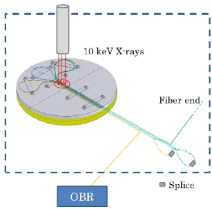
We developed a setup, reported in Fig. 1, that permits to control the irradiation temperature at the fiber level. It is composed of an aluminum plate on a heating plate (15 cm of diameter) positioned into the irradiation chamber. This design allows us to test three optical fibers at the same time; the samples were spliced each other and connected to the Optical Backscatter Reflectometer (OBR) to investigate the Rayleigh response. 10 keV X-ray irradiations were performed with a dose rate of 40 Gy/s up to accumulate a total dose of 1 MGy(SiO2) after 25000 s, the beam was centered in ~2 cm of the aluminum plate.
We followed the temperature profiles during the experiments thanks to type T thermocouples that were placed on the plate near the fiber in both non-irradiated and irradiated zone.
C. Distributed temperature measurements 1) Optical frequency domain reflectometry
Distributed temperature measurements were performed with an OBR 4600 from Luna Technologies. A schematic of OFDR optical network is shown in Fig. 2. The light from an external cavity tunable laser source (TLS) is split by a 3 dB coupler between the reference and the measurement arm of a Mach-Zender interferometer including the device under test (DUT). The backscattered light from the DUT is then recombined by another 3 dB coupler with the reference fields and the interference figure between the two arms is registered. Then, the Rayleigh signature as a function of the fiber length is calculated via a Fourier transform [14] - [16].
Fig. 2 Scheme of OFDR optical network
A distributed sensor is obtained by first measuring and storing the Rayleigh scatter profile of DUT in well-controlled temperature and strain conditions (reference state); then the measurement is repeated in a perturbed state (applied strain or changed temperature). The cross correlation between the data set in both states gives the information on the applied perturbation in terms of the spectral shift induced by temperature or by strain change. It is indeed known that Rayleigh spectral shift is a linear function of temperature and strain in agreement with Eq (1):
T
C
T
C
(1)where λ and ν are the central wavelength and frequency; CT and Cε are temperature and strain calibration coefficients (typical values for Germanium-doped silica core fibers are 6.48×10⁻⁶ ºC-1 and 0.780µε-1 [5], [14]) ΔT and ε are the applied temperature and strain changes. Thus, for a given optical fiber of which the calibration coefficients are known, once set the reference state through the measured spectral shift it is possible to perform distributed temperature or strain measurements.
In all measurements recorded the laser was centered at 1550 nm (with an accuracy of 1.5 pm) and tuned over a range of 21 nm (nominal spatial resolution of the Rayleigh scatter pattern of 0.040 mm). In this configuration the data acquisition rate limits maximum fiber length at ~70 m with an optical budget of 10 dB. Each measurement took less than 5 s for the 21 nm wavelength scan and associated calculations of spectral shift.
Measurements were performed on a ~10 m long sample composed by three fibers of ~2 m spliced each other; then a
zoom of each fiber in the irradiated zone of 4 cm (2 cm for each way) and in the near non-irradiated zone of 4 cm (again 2 cm for each way) was performed to analyze distributed temperature measurement with a spatial resolution of 0.2 cm.
2) Measurement procedure
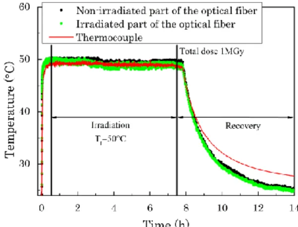
To investigate the transient effects on Rayleigh response we performed two types of experiments. The first, at fixed irradiation temperature (TI=50°C), is designed to evaluate the OBR response during both irradiation and recovery stages; an example of acquired data is shown in Fig. 3.
Fig. 3 Temperature as a function of time measured at fixed irradiation temperature (TI=50°C) during irradiation and recovery period for SMF-A1
pre-treated. Black circles indicate temperature calculated by Rayleigh measurements in the non-irradiated zone, green circles represent temperature values in the irradiated part of the sample; the red line is the temperature measured by the thermocouple.
Fig. 3 shows obtained results in fixed TI experiments. These results will be summarized in terms of ΔT between irradiated and non-irradiated part at the end of irradiation. Comparison with thermocouple data is achieved to demonstrate that temperature is well estimated by OBR. We note however that during the recovery the temperatures differ between thermocouples and fiber; the difference (~3 °C) is probably due to the packaging of the sensor or to the calibration procedure.
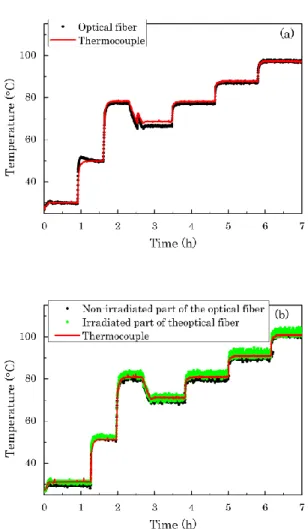
During the second experiment TI is varied during irradiation to investigate the OBR response in presence of evolving and combined radiation and temperature constraints. For DAC and HTA coated fibers (max operating temperature is respectively 80°C and 150°C) the temperature profile varies from 30°C to 80°C with three first heating steps at 30, 50 and 80°C that are followed by a step at 70°C; after this cooling step, the irradiation temperature was increased again up to 100°C by making three steps with a ΔT of 10 °C. For Pl and Pl&C coated fibers (max operating temperature is 300°C), we vary the temperature between 30 °C and 250 °C; for this we applied 10 temperature steps with a ΔT of 20 °C in the first step and then a ΔT of 25 °C up to reach 250 °C. We further divided this experiment in two runs to separate temperature and radiation contribution: in the first we studied the temperature profile described above without irradiation; this first run of the experiment behaves as a pre thermal treatment in as drawn samples and as a third thermal treatment in sample pre-treated
as explained in Section IIA. In the second run, without changing the fiber installation, we repeated the experiment during irradiation; the temperature curves are calculated by using the CT obtained from the first run. We report in this section an example of recorded data, Fig. 4 (a) and Fig. 4 (b) relative to an acrylate coated fiber, to lighten the reading in the results section. These set of data are useful to compare the OBR response with thermocouples temperature so as to highlight, if present, the radiation effect
.
Fig.4 Temperature as a function of time measured by varying TI (a)
without radiation and (b) with radiation for SMF-A1 pre-treated. Black circles indicate temperature calculated by Rayleigh measurements when radiation is absent in (a), and in the non-irradiated zone in (b); green circles represent temperature values in the irradiated part of the sample; the red line is the temperature measured by the thermocouple.
Fig. 4 (a) and Fig. 4 (b) show an example of collected data for the second experiment type at different TI where we see that OBR measured temperature well reproduces those given by thermocouples (except for the fourth step in Fig. 4 (a) where the experiment was affected by a small perturbation related to a transient dysfunction of the heating plate). From these we will highlight the differences between the two runs after a correction for the temperature fluctuations. Indeed the two runs were done during two different days explaining that the applied temperature profiles slightly differs and do not authorize a direct comparison. To achieve the comparison, we
correct the measured OBR temperature profiles by subtracting to the raw data the temperature fluctuations recorded by the thermocouples.
III. RESULTS AND DISCUSSION
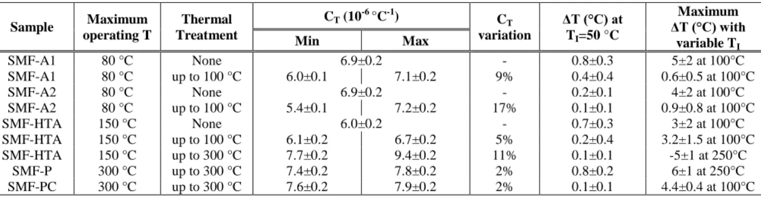
In this section we present the results for three different studied optical fibers: SMF-A1, SMF-HTA and SMF-PC. Reported results show a comparison between non-treated and pre-thermally treated fibers as well as the effects of different thermal treatments on coating properties focusing on the experiments at different TI. The same experimental study was performed on the other samples; a summary of the overall results is reported in Table 2.
A. Double acrylate coated fiber
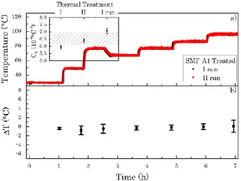
In Fig. 5 (a) we report the comparison of temperature evolution with time between non-irradiated fiber (I run) and irradiated fiber (II run) for the non-thermally treated sample SMF-A1. The first run allows us to determine the temperature coefficient of the whole fiber + plate system (CT = (6.9±0.2)×10-6 °C-1) to be used for the temperature measure. Temperature profile in both runs is similar and the irradiated curve exhibits a large temperature dispersion. In Fig. 5 (b) we report the temperature differences (ΔT) as a function of time. ΔT values are calculated from each step from the differences between T of the II run (with radiation) and T of the I run (without radiation) earlier corrected as explained in the last section. On the basis of the reported results we see that ΔT increases with time up to a maximum value of (5±2) °C at 100°C. Moreover, we note that the dispersion of the data increases with increasing temperature.
Fig. 5 (a) Temperature evolution as a function of the time for SMF-A1 non-thermally treated. Black squares indicate the first run without irradiation and red squares the second one in presence of radiation; (b) represents temperature differences between the two runs corrected with respect to the thermocouples values; the error bars are calculated by the error propagation from the dispersion in both run of OBR temperature data in each step.
Fig. 6 reports the experiment done in the same sample pre-thermally treated up to the maximum operating temperature of the coating (80 °C) and evidences that such a treatment makes the fiber more stable than its as drawn counterpart: the dispersion of temperature values is considerably reduced even at temperatures higher than 80°C. The inset shows the
evolution of CT during the two pre-thermal treatments and the run I of the experiment obtained from the calibration curve. CT increases with a variation between two consecutive treatments of ~10%. Therefore, ΔT values as a function of the time show that no radiation effects are present, these values being scattered around 0 °C during all the experiment.
The results on irradiation at fixed TI shown in Table 2 highlight an error of ~1 °C, constant during the irradiation, which is reduced to ~0.5 °C for pre-treated samples thus leading to a sensor with enhanced performances.
Fig. 6 (a) Temperature evolution as a function of the time for SMF-A1 thermally treated up to 80 °C. Black squares indicate the first run without irradiation and red squares the second one in presence of radiation; (b) represents temperature differences between the two runs corrected with respect to the thermocouples values; the error bars are calculated by the error propagation from the dispersion in both run of OBR temperature data in each step.
B. High temperature acrylate coated fiber
The experiments done on the treated SMF-HTA sample are reported in Fig. 7.
Fig. 7 (a) reports temperature as a function of time to compare non-irradiated and irradiated samples; the two profiles match each other. As reported in Table 2 the dispersion of temperature values decreases with respect to the non-treated sample from (0.7±0.3) °C to (0.2±0.4) °C. As above, the two thermal treatments allow us to stabilize the whole system before the experiment and also to study the evolution of CT that is reported in the inset of Fig. 7 (a). We observe in this case that CT increases in consecutive thermal treatments, its variation remaining within 5% from the mean values. Fig. 7 (b) shows ΔT as a function of time and evidences no temperature difference between the two runs, at least within the experimental uncertainty.
To compare the performances of SMF-HTA in different operating temperature ranges we have repeated the experiment heating the samples up to 300 °C. For this new experiment, as drawn sample was submitted, before the experiment, to the two temperature cycles from 30°C up to 300° (as explained in Section II A); the experiment varying TI are performed for this sample imposing the temperature profile from 30°C up to 250°C.
The results are reported in Fig. 8 (a) and Fig. 8 (b). The comparison between non-irradiated and irradiated fibers
shows that OBR distributed sensor remains functional in presence of both irradiation and high temperature.
The inset shows the evolution of CT with consecutive thermal treatments and highlights higher variation (10%) with respect to the previous experiment. From 30°C up to 150°C ΔT values are scattered around 0°C, after 150°C they decrease with time down to (-5±1) °C in the last step. A possible explanation of this break point, which occurs at the maximum operating temperature, is that the fiber is not stable and the dilatation of the plate and the coating introduce stress that gives an error on distributed measurement.
Fig. 7 (a) Temperature evolution as a function of the time for SMF-HTA thermally treated up to 80°C. Black circles indicate the first run without irradiation and red circles the second one in presence of radiation; the inset shows the evolution of CT during the three thermal treatments; (b) represents
temperature differences between the two runs corrected with respect to the thermocouples values; the error bars are calculated by the error propagation from the dispersion in both run of OBR temperature data in each step.
Fig. 8 (a) Temperature evolution as a function of the time for SMF-HTA thermally treated up to 300°C. Green circles indicate the first run without irradiation and blue circles the second one in presence of radiation; the inset shows the evolution of CT during the three thermal treatments; (b) represents
temperature differences between the two runs corrected with respect to the thermocouples values; the error bars are calculated by the error propagation from the dispersion in both run of OBR temperature data in each step.
TABLE 2SUMMARY OF DATA RECORDED FOR THE FIVE SAMPLES DURING THE EXPERIMENTS Sample Maximum operating T Thermal Treatment CT (10-6 °C-1) CT variation ΔT (°C) at TI=50 °C Maximum ΔT (°C) with variable TI Min Max SMF-A1 80 °C None 6.9±0.2 - 0.8±0.3 5±2 at 100°C SMF-A1 80 °C up to 100 °C 6.0±0.1 7.1±0.2 9% 0.4±0.4 0.6±0.5 at 100°C SMF-A2 80 °C None 6.9±0.2 - 0.2±0.1 4±2 at 100°C SMF-A2 80 °C up to 100 °C 5.4±0.1 7.2±0.2 17% 0.1±0.1 0.9±0.8 at 100°C SMF-HTA 150 °C None 6.0±0.2 - 0.7±0.3 3±2 at 100°C SMF-HTA 150 °C up to 100 °C 6.1±0.2 6.7±0.2 5% 0.2±0.4 3.2±1.5 at 100°C SMF-HTA 150 °C up to 300 °C 7.7±0.2 9.4±0.2 11% 0.1±0.1 -5±1 at 250°C SMF-P 300 °C up to 300 °C 7.4±0.2 7.8±0.2 2% 0.8±0.2 6±1 at 250°C SMF-PC 300 °C up to 300 °C 7.6±0.2 7.9±0.2 2% 0.1±0.1 4.4±0.4 at 100°C
C. Polyimide coated fiber
Fig. 9 reports the characterization on SMF-PC thermally treated up to 300 °C. The comparison between non-irradiated and irradiated fibers shows that OBR distributed sensor operates in presence of both irradiation and high temperature up to 250 °C. The inset displays that CT in this sample is stable in consecutive thermal treatments and the variations are of 2%. ΔT values in Fig. 9 (b) highlight that in the firsts steps up to 90 °C there are differences between non-irradiated and irradiated fiber (maximum variation of (4.4±0.4) °C). At temperature higher than 100 °C the values are scattered around 0 °C and we do not observe any temperature variation, at least within the experimental uncertainty.
Fig. 9 (a) Temperature evolution as a function of the time for SMF-PC thermally treated up to 300°C. Green circles indicate the first run without irradiation and blue circles the second one in presence of radiation; the inset shows the evolution of CT during the three thermal treatments; (b) represents
temperature differences between the two runs corrected with respect to the thermocouples values; the error bars are calculated by the error propagation from the dispersion in both run of OBR temperature data in each step.
From the results reported in Fig. 9 and Table 2 we observe that polyimide coated fibers exhibit a more complex behavior. They are the most stable fibers in terms of CT evolution, but the experiments highlight that distributed measurements are affected by errors that depend on the packaging of the samples. These errors are not related to a specific temperature (as in the case of HTA sample) and may be linked to stress locally induced by the plate into the sample that alters the
traces. We are confident that by working on the sensor design, these errors will be reduced below 1 °C over the while range.
All results show that radiation does not affect the physical phenomenon (Rayleigh scattering) at the basis of OFDR distributed temperature measurement but also make clear that a contribution of packaging on distributed measurements has to be considered. A. Faustov in [11] has shown for his distributed temperature experiments that the metallic tube used to protect the fiber during its measurements influences the results by changing the calibration curves. Our results confirm the importance of packaging and in particular we show that at the first step the coating itself affects temperature measurements. We show indeed that performing a pre-treatment on the whole samples improves the performances of the sensor. These results agree with our recent study [12] where we demonstrate that for DAC optical fibers CTs stabilize with consecutive thermal treatments reducing error induced by calibration procedure. This behavior is due to the properties of acrylate and in particular the mismatch of the thermal expansion coefficient between silica glass and the secondary coating induced internal strain into the optical fiber by a thermal shrinkage that occurs at ~90°C corresponding to the transition temperature, Tg, of the secondary coating [17] [18]. So, the first thermal treatment induces into coating a dilatation that releases stress into the fiber changing its initial configuration. This work also suggests that for industrialization of such sensor, the role of the cable in addition to coating will have to be investigated to allow achievement of best performances.
IV. CONCLUSION
In this work we have investigated in situ Rayleigh response of five single mode optical fibers in the class of radiation resistant ones. Performed experiments point out that OFDR sensors are unaffected by radiation at least up to the explored doses. Nevertheless, our results (summarized in Table 2) make clear that the installation of these devices is an awkward procedure that can introduce errors in the measurements. For this reason here we have dealt with the packaging problem to evaluate a process in the sensor built to avoid, where possible, the packaging issue. We have demonstrated that a pre-thermal treatment up to the maximum operating temperature of the coating is mandatory to stabilize the fiber before its employment in the designed environment. In fact, we are able
to reduce the accuracy of the measurement down to ~0.5 °C when the temperature varies during irradiation and to eliminate inaccuracies introduced by the packaging. The behavior is different if the fiber is heated up to the maximum operating temperature of the coating, where we observe a break point around the threshold value after which sensor performances decrease. All the collected results offer a good view of ODFR-sensors area of applications and open the way to build new generation of radiation hardened sensors for nuclear facilities.
REFERENCES
[1] S. Girard, J. Kuhnhenn, A. Gusarov, B. Brichard, M. Van Uffelen, Y. Ouerdane, A. Boukenter, and C. Marcandella, “Radiation Effects on Silica-Based Optical Fibers: Recent Advances and Future Challenges,”
IEEE Trans. Nucl. Sci., vol. 60, no. 3, pp. 2015 - 2036, 2013.
[2] A. Morana, S. Girard, E. Marin, C. Marcandella, P. Paillet, J. Périsse, J.-R. Macé, A. Boukenter, M. Cannas, and Y. Ouerdane, “Radiation tolerant fiber Bragg gratings for high temperature monitoring at MGy dose levels,” Opt. Letters, vol. 39, no. 18, pp. 5313-5316, 2014. [3] X. Phéron, S. Girard, A. Boukenter, B. Brichard, S. D. Lesoille, J.
Bertrand, and Y. Ouerdane, “High γ-ray dose radiation effects on the performances of Brillouin scattering based optical fiber sensors,” Opt.
Express, vol. 20, no. 24, pp. 26978-26985, 2012.
[4] C. Cangialosi, Y. Ouerdane, S. Girard, A. Boukenter, S. Delepine-Lesoille, J. Bertrand, C. Marcandella, P. Paillet, M. Cannas, “Development of a Temperature Distributed Monitoring System Based on Raman Scattering in Harsh Environment,” IEEE Trans. Nucl. Sci., vol. 61, no. 6, p. 3315 – 3322, 2014.
[5] B. J. Soller, D. K. Gifford, M. S. Wolfe and M. E. Froggatt, "High resolution optical frequency domain reflectometry for characterization of components and assemblies," Opt. Express, vol. 13, no. 2, pp. 666-674, 2005.
[6] A. V. Faustov, A. Gusarov, L. B. Liokumovich, A. A. Fotiadi, M. Wuilpart, P. Mégret, “Comparison of simulated and experimental results for distributed radiation-induced absorption measurement using OFDR reflectometry,” Proc. SPIE, vol. 8794, no. 87943O, 2013.
[7] S. Girard, C. Marcandella, A. Morana, J. Perisse, D. Di Francesca, P. Paillet, J.- R. Macé, A. Boukenter, M. Léon, M. Gaillardin, N. Richard, M. Raine, S. Agnello, M. Cannas, and Y. Ouerdane, “Combined High Dose and Temperature Radiation Effects on Multimode Silica-Based Optical Fibers,” IEEE Trans. Nucl. Sci., vol. 60, no. 6, pp. 4305-4313, 2013.
[8] M. Van Uffelen, “Modélisation de systèmes d’acquisition et de transmission à fibres optiques destinés à fonctionner en environnement nucléaire,” Ph.D. dissertation, Univ. de Paris XI, Paris, France, 2001. [9] S. Rizzolo, A. Boukenter, E. Marin, M. Cannas, J. Perisse, S. Bauer, J-R.
Mace, Y. Ouerdane, S. Girard, “Vulnerability of OFDR-based distributed sensors to high γ-ray doses,” Opt. Express, vol. 23, no. 15, pp. 18997-19009, 2015.
[10] S. Rizzolo, E. Marin, M. Cannas, A. Boukenter, Y. Ouerdane, J. Perisse, S. Bauer, J-R. Mace, C. Marcandella, P. Paillet and S. Girard, “Radiation Effects on OFDR based sensors,” Opt. Letters, Accepted to, 2015.
[11] A. Faustov, “Advanced fibre optics temperature and radiation sensing in harsh environments,” Ph.D. dissertation, Univ. de Mons, Mons, Belgium, 2014.
[12] S. Rizzolo, C. Sabatier, A. Boukenter, E. Marin, Y. Ouerdane, M. Cannas, J. Perisse, J-R. Mace, S. Bauer and S. Girard, “Radiation Vulnerability of Optical Frequency Domain Reflectometry Fiber-Based Distributed Sensors,” IEEE Trans. Nucl. Sci., Submitted to, 2015. [13] P. Paillet, J.R. Schwank, R. Shaneyfelt, M. V. Ferlet-Cavrois, R.L.
Jones, O. Flament, E.W. Blackmore,, "Comparison of charge yield in MOS devices for different radiation sources," IEEE Trans. Nucl. Sci., vol. 49, no. 6, pp. 2656-2661, 2002.
[14] B. J. Soller, M. Wolfe, M. E. Froggatt, "Polarization resolved measurement of Rayleigh backscatter in fiber-optic components," in OFC Technical Digest, Los Angeles, 2005.
[15] R. G. Duncan, B. J. Soller, D. K. Gifford, S. T. Kreger, R. J. Seeley, A. K. Sang, M. S. Wolfe, and M. E. Froggatt, “OFDR-Based Distributed Sensing and Fault Detection for Single- and Multi-Mode Avionics
Fiber-Optics,” Luna Technologies, A Division of Luna Innovations Incorporated, 3157 State St., Blacksburg, VA 24060, 2003.
[16] S. T. Kreger, A. K. Sang, D. K. Gifford, M. E. Froggatt, “Distributed strain and temperature sensing in plastic optical fiber using Rayleigh scatter,” Proc. SPIE, pp. 73160A-1, 2009.
[17] Yasuo Nakajima, Hiroki Tanaka, Kouji Mochizuki, Kazuyuki Fuse,Yoshihiro Arashitani, Takuya Nishimoto, Atsuyoshi Seno and Mitsunori Okada, “A Study for Estimating Thermal Strain and Thermal Stress in Optical Fiber Coatings,” Furukawa Review, vol. 34, no. 8-12, 2008.
[18] Yasuo Nakajima, Kouji Mochiduki, Hiroki Tanaka, Yoshihiro Arashitani, Takuya Nishimoto, Mitsunori Okada, “Thermal Strain of Optical Fiber Coatings Using CTE Measurement,” in International Wire & Cable Symposium, Florida (USA), 2007.