OATAO is an open access repository that collects the work of Toulouse
researchers and makes it freely available over the web where possible
Any correspondence concerning this service should be sent
to the repository administrator:
[email protected]
This is an author’s version published in:
http://oatao.univ-toulouse.fr/24346
To cite this version:
Michau, Alexandre and Gazal, Yoan
and Addou, Fouzi and Maury, Francis
and Duguet, Thomas
and Boichot, Raphaël and Pons, Michel and Monsifrot,
Eric and Maskrot, Hicham and Schuster, Frédéric Scale up of a DLI-MOCVD
process for the internal treatment of a batch of 16 nuclear fuel cladding segments
with a CrCx protective coating. (2019) Surface and Coatings Technology, 375.
894-902. ISSN 0257-8972
Scale up of a DLI-MOCVD process for the intemal treatment of a batch of 16
nuclear fuel cladding segments with a CrCx protective coating
A. Michau
a•
*
, Y. Gazal
h,
F. Addou
a, F. Maur
l
, T. Duguet
h,
R.
Boichot
C,
M. Pons
C,
E.
Monsifrot
d,
H.
Maskro
t'
,
F.
Schuster
e• Den....Sen,iœ d'Etudes Analytiques et de Rlactlvtté des S,rfaœs (SEARS), CEA, Univemli Paris-Saclay, 91191 Gif sur Yvette, Prame
b ClRIMAT, CNRS/lNPT /UPS, 4 allée E. Monso, 31030 Toulouse cedex 4, Prame
• lJn1verslty Grenoble A�es, SIMAP, CNRS, 38QOO Grenoble, France
d Dephis, 74 rue Armand Japy, 2S46C Ettpes, France
•cEA Cross�protf'am on Materials and Processes Skllis, 91191 Gif·SU1'-Y"'1tt, Fronœ
ARTICLE INFO Keywords: DU-MOCVD Scale-up Cr-based coatlngs Internai protection Nuclear fuel cladd!ngs EATP
1. Introduction
ABSTR A CT
Direct liquid injection - metalorganic chemical vapor deposition (DU-MOCVD) is the most advanced process dedicated to the internai protection of nuclear fuel cladding in accident conditions such as Joss of coolant. It allows the deposition of an amorphous, glassy-like chromium carbide OC. coating which is resistant against high-temperature oxidation in air and steam. Since the above-mentioned material characterizations demon strated that coatings possessed the appropriate protection properties, the DU-MOCVD process was scaled-up.
Flrst, a joint development between experimental and numerical studies led to a deposition inside a 1 m long cladding segment with a coating of sufficiendy large and uniform thickness. Optimized reactor parameters consist in a combination oflow temperature (-600 K) and low pressure (-600 Pa) with a high vapor flow rate of reactive species in the reactor ensuring a short residence lime. The second phase of the scale-up consisted in coating simultaneously three, then sixteen segments in a single run. 3D computational simulations of the de position process assisted the development of specific flanges designed to distribute homogeneously the reactive vapor into the three or sixteen cladding tubes. Experimental conditions have been extrapolated from one to three and to sixteen cladding segments, resulting in the deposition of the OC. coating inside ail segments with a relatively uniform partition.
Overall, this paper demonstrates the feasibility of the deposition of CrC. coating in a bundle of several, up to sixteen, nuclear fuel cladding segments of 1 m in length (ID 8 mm), in order to protect them during accident conditions. This "batch demonstration" is a first step in the course of DU-MOCVD technological transfer. Next step will be the deposition in a full-length cladding tube (4 m) that is already supported by numerical predic tions.
Fukushima Daiichi accident triggered a worldwide effort devoted to the enhancement of global existing safety in nuclear reactors. The first fission products containment barrier consisting of cladding tubes are one of the studied crucial improvements through the development of EATF (Enhanced Accident Tolerant Fuels). Among ail EATF short term or mid term solutions, various concepts focus on the protection of fuel cladding on their outer wall during accidentai conditions such as LOCA (Loss Of Coolant Accident) [1,2).
fuel claddings rely generally on physical phenomena. We can cite on one hand cold spray [3,4) and other projection technologies based for example on laser [5) meant for thicker layers and on the other hand thinner films obtained by sputtering and evaporation during PVD gas phase processes [6,7). Two main routes of elaboration emerge from these techniques. First, melted or unmelted mater is projected on a substrate. Second, a solid source is transferred into vapor and then condensates on a substrate. In both cases, the influx of mater partici pating to the coating growth is directional and needs to be controlled. lt can be unmelted powder accelerated at a high velocity by a pre heated gas, laser mehed powder projected again with the help of a carrier gas or plasma assisted sputtering and subsequent condensation of a solid PVD techniques such as magnetron sputtering, and other deposition
processes studied by the nuclear community to coat the outer surface of
• Corresponding author at CEA Saclay, Building 467, Room 206, 91191 Gif-sur-Yvette, France.
E-mail address: [email protected] (A. Michau).
2. Experimental and calculations
Strem Chemicals Inc. supplied bis(ethylbenzene)chromium (BEBC) used as molecular precursor. It is in fact a liquid mixture of several bis (arene)chromium compounds [(C2H5)x(C6H6 x)]2Cr where “x” varies
from 0 to 4. The relative content of BEBC (i.e. x = 1) in this solution is around 70%. It was used as chromium source as received because all these bis(arene)chromium compounds exhibit very similar properties as molecular precursor for CVD. Toluene (purchased from Sigma Aldrich, purity 99.8%) was used as solvent. A liquid solution consisting of BEBC and toluene is injected in a vaporization chamber heated at about
423 K. N2was chosen as dilution gas because it is inert at the low
temperatures used (≤723 K). After being generated in a Kemstream vaporization chamber, the reactive vapor is then transported inside one or several Zr based fuel cladding segments via thermostated stainless steel pipes. Fuel cladding tubes, assimilated to long (1.2 m) and narrow (ID 8 mm) reactors, are positioned along the axis of a tubular three zone
furnace. Three configurations were studied with 1, 3 and 16 claddings
segments coated during the same batch. Special gas phase distributors
divide as homogeneously as possible the gas flow into the 3 or 16
segments. Activated by the temperature, the reactive gas phase de
composes and forms amorphous chromium carbide coatings (a CrCx)
inside the claddings. A roots pump and a monitored butterfly valve allow working at controlled reduced pressure (130 3330 Pa). Between the reactor and the vacuum pump, a two stage liquid nitrogen cold trap condensates the reaction byproducts, as well as the unreacted chemi cals.
As deposited coating microstructure and thickness were analyzed by Scanning Electron Microscopy (SEM; Leo 435VP) on cross sections. Their compositions were checked with Electron Probe MicroAnalysis (EPMA; Cameca SXFive, 15 kV and 20 nA).
Numerical modeling tools consisted in CFD ACE multi physics target for example. Because they are directional and depends on phy
sical phenomena, the processes using these routes comply charitably for their scale up [8,9].
Interestingly, diffusion and conversion processes such as ion im plantation did not flourish yet from the literature for nuclear cladding application at a significant scale [10,11] but exist for other applica
tions. Plasma nitriding, a thermochemical diffusion process for surface hardening at low temperature applies extensively and successfully in nuclear industry to stainless steels [12]. For instance, industrial in
stallations at Nitruvid in France dedicated to the hardening of control rod cluster tubes consist in pit furnaces with a 2 m diameter and a 6.5 m length [13]. Framatome sells these kinds of enhanced wear resistant
assemblies under the commercial name HARMONI™. So far, several thousands of HARMONI™ assemblies have been installed and operated
in numerous nuclear power plants around the globe [14].
Generally opposed to physical deposition techniques, CVD (Chemical Vapor Deposition) processes involve by definition a set of chemical reactions. This so called mechanism has the particularity to take place in homogeneous and heterogeneous phases, i.e. in the vo lume of the deposition chamber and necessarily at its surface too. Molecular precursors used in CVD processes provide the intermediate species required for the growth of the coating. Because of several rea sons, for example, (i) the complexity of the decomposition mechanism which strongly depends on the surface over volume ratio, (ii) the homogeneous reactive gas phase flow that needs to feed continuously and uniformly the deposition chamber and the sample surface to be coated and, (iii) the activation of the decomposition mechanism which must be precisely controlled in the vicinity of the component to coat, CVD processes consent less willingly to be scaled up. Doubling the in flux of mater is typically not making the coating growth twice faster. Progressive scaling is generally performed for straightforward chemis tries, well understood and controlled, such as with simple molecular precursors of halide, hydride or oxide type [15,16].
As mentioned in the beginning of the introduction, EATF aims at providing a more robust solution for nuclear fuel claddings in accident conditions. However, when exposed to a coolant limitant accident, all coated Zr based cladding concept suffer from the same weakness after their ballooning and bursting. High temperature steam have access to the unprotected inner surface of the cladding, leading to its fast inner oxidation and secondary hydriding, which induces significant addi tional embrittlement of the claddings [17].
In order to assess this issue, a special gas phase process, DLI
MOCVD (Direct Liquid Injection MetalOrganic Chemical Vapor
Deposition), was investigated and scaled up in the perspective of de positing an inner side protection coating all along fuel claddings [18,19]. DLI MOCVD is an emerging process, which is widely used
essentially for oxide deposition because organic solvents are often used, therefore with risk of carbon co deposition that can easily be removed by using an oxidizing atmosphere since oxides must be deposited [20].
Even if this technique is generally used for oxides, it was also used to deposit noble [21,22] or non noble metals [23], as well as more rarely
nitrides [24] and carbides [18,25]. With recent works on nitrides and
carbides of transition metals, it appears as an emerging process for metallurgical coatings [26]. The development of DLI MOCVD process is
underway, keeping in mind that nowadays, a technological demon stration of a process is not enough. Economic viability and ecological impact have to be quantified in order to assess the entire in dustrialization potential of the process. These aspects will be discussed along this paper.
In order to efficiently protect the internal surface of a nuclear fuel cladding, the deposited coating has to satisfy at least 3 main criteria: (i) to be a good sacrificial barrier against high temperature oxidation, (ii) to exhibit a homogenous thickness all along the cladding tube (4 m) and (iii) to have a thickness of several microns. The first requirement was
previously demonstrated for amorphous chromium carbide a CrCx
coatings [27]. This is in agreement with the good corrosion and
oxidation resistance of Cr7C3 at high temperature [28]. The second and
the third criteria could be satisfied by an ALD process, as reported in a complex cooling circuit but ALD suffers from very low growth rates, which is not adapted to develop protective coatings about 10 μm thick [29]. These last two criteria can be addressed by the CVD technique
with the help of numerical modeling. In fact, simulating the coating deposition guides us towards several potential solutions for these last two points. Indeed, we were able to demonstrate the possibility in two steps to successively and alternatively inject the reactive gas phase at each end of the cladding segment to achieve a good compromise be tween both thickness uniformity and average thickness of coatings grown at 673 K [30]. However, for an industrial development, the op
timization of the deposition conditions in only one step is preferred to simplify the process, which is precisely the aim of this paper.
From the state of the art in the CVD community, it is known that both low deposition temperature and total pressure are mandatory in order to get a good uniformity of thickness in long and large scale re actors [31] and/or on complex shape pieces as composite ceramic
materials [32]. However, it usually leads to a very poor conversion
yield of the precursor, which significantly impacts the cost of the pro cess when expensive metalorganic compounds are used. For the selec tion of the chemical system of this study this issue has been considered in the early stage of the program and it was adequately selected to allow the integration to the process of a loop recycling system, which is very rare in CVD, thus compensating this drawback [18]. Therefore two
main routes have been explored here: (i) the application of a tem perature gradient in the reactor axis to compensate the precursor de pletion, responsible for the decrease of the growth rate along the axis and (ii) the conjugated effect of low temperature, low pressure and high total gaseous flow rate, these last two parameters reducing the re sidence time of reactive species inside the reactor. This paper deals with these results and particularly focuses on the scale up of the deposition process.
along the cladding tube due to its consumption. As a result, the goal is to set accurate parameters in order to get both the best thickness uni
formity of thefilm and an average thickness sufficient to act as a good
sacrificial barrier in EATF conditions.
Several parameters control the growth rate of thefilm along the fuel cladding, the most important being: the total pressure, the total gas flow rate and the growth temperature. They have all a great influence
on the growth rate of thefilm particularly because they influence the
residence time of reactive species in the tube. Obviously the working temperature is the most critical parameter in CVD because it acts both on the main features of the deposited material and on chemical reac tions which are thermally activated according to an Arrhenius kinetic law.
In the present work, several ways have been investigated to improve the growth rate profile along the cladding tube, all of them coupled with numerical simulations:
(i) Optimization of the growth conditions by studying the effect of
previously unexplored conditions as lower pressures (≤660 Pa),
higher totalflow rates (≥500 sccm) and lower growth tempera
tures (≤673 K) in order to decrease the residence time of reactive species by increasing the vapor velocity and to act on the kinetics of the process.
(ii) Applying a linear temperature gradient along the reactor (positive downstream);
(iii) Inject successively and alternatively the reactive gas phase at each end of the fuel cladding tube (two step process);
3.1.1. Influence of the total pressure
Thefirst films were synthesized at a temperature and a pressure of
673 K and 2000 Pa respectively and 500 sccm of N2as dilution gas.
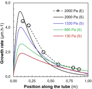
Fig. 1shows the thickness variation of such a coating along the inside of the cladding tube. The growth rate reaches a maximum near the en trance of the tube, and then it decreases continuously downstream due to the consumption of the precursor. These conditions lead to a rela tively sharp thickness gradient to such an extent that there is no deposit near the exit of the tube. There is a good agreement with the corre
sponding simulation curve confirming that the simplified kinetic model
used is useful in these conditions. In this simulation, to gain calculation time, the thermal profile applied on the external wall of the fuel clad ding segment is isothermal. Interestingly, theFig. 1also shows that the thickness uniformity is improved by decreasing the total pressure but this is detrimental to the average growth rate and the conversion rate of the precursor. For instance, the growth rate ratio Gm/G1between the
maximum near the entrance and the value at the abscissa 1 m (the outlet) decreases from 35.0 to 5.3 by decreasing the pressure from 2000 to 660 Pa, respectively.
3.1.2. Influence of the total flow rate
Towards the objective to coat uniformly the internal surface of a 4 m long fuel cladding, the growth rates have to be mitigated in thefirst half of the tube, as well as the reaction yield. That is why we investigated working at even lower temperature and higher velocity of the gaseous phase. The working temperature and pressure were set at 623 K and
660 Pa respectively and the N2flowrate varies from 500 to 1000 sccm.
Fig. 2displays the experimental thickness profile for each experiment,
compared with simulated ones where an ideal isothermal profile is applied on the outer wall of the cladding.
By combining the effect of a low temperature (623 K) and pressure (660 Pa), it is possible to obtain flatter growth rate profiles. For ex ample, for totalflow rate of 500 sccm the theoretical ratio Gm/G1= 1.7.
The numerical model of the coating deposition provides correct ten dencies. An increase of the dilution gasflow rate leads to an increase of the gases velocity. The residence time of reactive species is shorter,
decreasing the maximum growth rate (Gm) and slightly smoothening
the profile. Although the simulation does not fit well experimental data
Fig. 1. Influence of the total pressure on the growth rate of a-CrCxcoatings
inside and along a 1 m long cladding tube: experimental data (E) obtained at 2000 Pa and 673 K is compared to simulation curves (S) for different pressures in the range of 130 to 1330 Pa while other parameters are kept constant (500 sccm of N2, 4.4 sccm of BEBC and 108 sccm of toluene).
simulation software package [33]. Details on the model and the simu
lations are described elsewhere [30]. Numerical simulations provide
robust kinetic and multicomponent transport models capable of pre dicting amorphous chromium carbide coating growth in claddings, from centimetric segments to metric ones and even to full length cladding tubes (4 m) as it is presented further. For single cladding ex periments, a 2D axisymmetric modeling was implemented and full 3D modeling was used for the scale up (bundle of three and sixteen clad dings and full length simulations). Structured mesh composed the 2D axisymmetric model while the full 3D models combined structured mesh for cylindrical parts and unstructured mesh for gas phase dis tributors.
3. Results and discussion
3.1. Coating in a 1 m long fuel cladding segment
As stated in the introduction and evidenced in previous works [27],
amorphous CrCx coatings are suitable to protect fuel cladding from
oxidation at high temperature. The efficiency of these protection bar riers is due to their homogeneous and glassy like morphology. Fur thermore, they exhibit a dense and amorphous structure without grain boundaries. These structural features were found for all the growth conditions previously investigated, e.g. in the temperature range 673 773 K and the total pressure 660 6660 Pa [18,27,30].
An optimization preliminary to the scale up of the deposition pro cess was realized through experimental parameter adjustment assisted by multi physics computational simulations and using a simplified ki netic model in order to demonstrate its viability to protect cladding segments in a pilot reactor. As a result, computational simulations provide a set of optimal deposition parameters to coat homogeneously the inner surface of a fuel cladding segment of 1 m long that can be extrapolated to multi cladding segments deposition.
The main issue we have to address first is the non uniformity of the film thickness along a 1 m fuel cladding segment. Such issue is inherent in any CVD process when complex geometries [34], for instance long
segments, have to be coated without moving them in the furnace (or without moving the furnace). Generally the growth rate goes through a maximum before decreasing downstream as shown for instance in
the tendencies are good, especially for 500 sccm. The disagreement could be due to limitations in the simplified kinetic model used that did not hold in these conditions such as very low temperature (623 K).
3.1.3. Influence of the deposition temperature
Another way to make the growth rate profile as uniform as possible is a decrease in the working temperature of the furnace. This effect is well known theoretically and experimentally for CVD processes. Indeed, as shown inFig. 3, the growth rate profile of a deposition at
623 K is much smoother than the one at 648 K. The BEBC precursor is in fact very sensitive to small changes in this temperature range and the relatively low value of N2gaseousflow is amplifying this effect. Sur
prisingly, in the deposition conditions ofFig. 3, the maximum experi mental growth rates are very high compared to the numerical calcu
lations superimposed on thisfigure.
Even if the tendencies are fair for our model, thefit with experi
mental data is clearly not satisfying for low deposition temperatures.
Fig. 2. Experimental growth rate profiles (E) of a-CrCxcoatings deposited
in-side a 1 m long fuel cladding segment at 660 Pa, 623 K, 500 and 1000 sccm of N2, 8.8 sccm of BEBC and 98 sccm of toluene compared with simulated ones (S).
Fig. 3. Experimental growth rate profiles (E) of a-CrCxcoatings deposited
in-side a 1 m long fuel cladding segment at 400 Pa, 623 and 648 K, 250 sccm of N2,
8.8 sccm of BEBC and 98 sccm of toluene compared with simulated ones (S).
The simplified kinetic model of a CrCx growth [30] ought to be re
visited for temperatures lower than 673 K. It was indeed developed for similar total gaseous flow rate but for higher temperatures, between 673 and 823 K, and higher pressures, between 7000 and 700 Pa. It appears that the model would not be pertinent outside these boundaries at lower temperatures and pressures. Several reactions that were dis carded at low temperature and pressure because of their minor parti cipations to the growth mechanism could be now predominant and should be included in further works.
3.1.4. Application of a temperature gradient along the tube
In order to compensate for the axial depletion of the reactive spe cies, and to produce a uniform deposition rate, a typical method is to enhance thermally the growth rate of the film along the tube in CVD conditions where the process is kinetically controlled by surface reac tions. This method is applied for a long time in the semiconductor in dustry in hot wall horizontal reactors for polysilicon deposition and other functional thin films [35].
Since our three zone furnace allows a gradient to be set, the solution of applying a downstream positive temperature ramp has been in vestigated. A quasi linear gradient is achieved by setting 648 K at the entrance of the furnace and 673 K at the exit and the pressure is reduced at 660 Pa. Fig. 4(a) shows the experimental growth rate profile, com pared with two simulated curves. The first one (black continuous line) uses the experimental thermal profile measured inside the cladding segment, while an ideal linear thermal gradient of 25 K·m−1 is applied
for the second one (blue continuous line). These two thermal profiles are presented in Fig. 4(b).
Actually, our commercial three zone furnace was not designed to provide a very good linear thermal gradient at very low temperature but rather an isothermal profile (slope changes occur between each zone even for different PID tuning). However, a better knowledge of the experimental thermal field provided by the furnace allows the numer ical modeling to calculate a more realistic growth rate profile and to fit better experimental data. It is also worth noticing that, as predicted, by simultaneously decreasing the pressure and using a temperature gra dient, the growth rate profiles become a little bit more uniform (Gm/
G1 = 2.2), but not yet suitable. However, this method remains a pro
mising route using a more appropriate furnace. 3.1.5. Alternative injection at each end of the cladding tube
As mentioned in the introduction, the process can be carried out in two deposition steps where the reactive gas phase is alternatively in jected at each end of the cladding tube. This is performed without turning off the furnace and without venting in ambient air the cladding before running the second step (only a short purge under N2 could be
applied before the second step). Indeed, after a first deposition step, the reactive gas phase can be transported over a longer distance to be in jected at the other end of the cladding tube.
To simulate experimentally this idea and simply demonstrate its feasibility, the furnace was stopped after the first run, and then the cladding tube was reversed once it was at room temperature with a passage to the ambient air. This simple method avoids technically modifying the DLI MOCVD pilot currently in development. As a result, the two steps correspond to the deposition runs performed in the two directions. All the parameters are kept constant during the two steps (673 K, 1330 Pa and 500 sccm) and each run has the same duration of 3 h. In such conditions, the experimental growth rate profile along the tube is displayed in Fig. 5. As expected, the thickness profile is quite symmetrical. It however exhibits two maxima, near the entrance of each run, that means near each end (around abscises of 0.20 m and 0.85 m) once the two step process is finished.
Applying these experimental conditions, a numerical simulation was performed using an ideal isothermal profile. The simulated curves are also drawn in Fig. 5. The numerical results are in very good agreement with the experimental ones although the growth rates were slightly
overestimated at the beginning of the deposition in the segment. Moreover, there is a slight shift of the two maximum values of the si mulated growth rate profile towards the exterior of the furnace due to the non ideality of the real furnace temperature profile, where the working temperature is not achieved through the whole furnace but on a limited length.
The alternate injection method at each end could be an alternative to get bothfilm thicknesses more uniform and thicker. The fact that the
thickness profile is symmetrical constitutes also an advantage. This
method however requires performing the deposition in two steps, which does not seem to be a problem for an industrial process since the reactive gas phase can be transported alternatively towards each end of the cladding tube without stopping the heating and pumping, and therefore without venting the samples.
3.2. Upscaling the process
3.2.1. Bundle of 1 m long cladding segments
Passing from a single 1 m long cladding segment to a bundle of several segments 1 m long is as important as demonstrating the feasi bility of coating the inside of a full length of a single cladding. This approach can be considered as a step towards mass production. Two configurations were designed to uniformly distribute the reactive vapor
phase in each tube of two batches: the first one consisted of 3 clad
segments and the second of 16 clad segments. The results of these two DLI MOCVD runs are described and discussed below.
As for the deposition in a single clad segment where the deposition chamber is directly the cladding tube, the same principle was applied for these segments bundle. Two major parameters have to be con sidered in CVD processes: the activation method of the molecular pre
cursor and the highflow rate supply of reactive vapor. Depending on
the design of the reaction chamber and the geometry that need to be coated, these parameters must be specifically adapted. They generally have to be homogeneous or gradient controlled through the entire vo lume of the chamber in order to ensure the uniformity of the coating thickness and properties. DLI MOCVD process studied for the inner protection of fuel claddings studied here is thermally activated at low temperature. Practically, the same three zone furnace heats the clad segments, which are connected to the reactive vapor supply through a gas phase distributor. On the exhaust side, the same type of connection is done, leading to the trapping and pumping systems.
The specific gas phase distribution systems were numerically de
signed and then validated with the help of computational fluid dy
namics (Fig. 6). A homogeneous gas repartition along all the 3
(Fig. 6(a)) or 16 (Fig. 6(b)) clad segments can be ensured. Finally, the distribution systems were fabricated through conventional machining. Further developments are under consideration using additive manu facturing to achieve bigger and more efficient gas distribution systems based on optimized designs. The optimization of the deposition para meters in the present configuration is currently in progress, based on our previous results [30] and the tendencies is described in this section. Depositions in a bundle of segments consisted for the moment in the extrapolation of an experimentally satisfying deposition configuration in a single cladding segment, coupled with our current technological limits, mainly in terms of vaporization. The reference conditions that were extrapolated are the following: 598 K and 660 Pa with 400 sccm of
Fig. 4. (a) Experimental (E) and simulated (S) growth rate profile of an a-CrCx
coating deposited inside a 1 m long fuel cladding segment at 660 Pa with the real and an ideal thermal gradient (648 to 673 K), 500 sccm of N2, 8.8 sccm of
BEBC and 98 sccm of toluene and (b) real (-o-) and ideal (blue straight line) thermal gradient profiles. (For interpretation of the references to color in this figure legend, the reader is referred to the web version of this article.)
Fig. 5. Experimental (E) growth rate profile of a a-CrCxcoating deposited in
two steps inside a 1 m long fuel cladding segment at 1330 Pa, 673 K, 500 sccm of N2, 4.4 sccm of BEBC and 108 sccm of toluene compared with simulated (S)
N2, 8.8 sccm of BEBC and 98 sccm of toluene. The corresponding ex
perimental growth rate profile in a single cladding is given inFig. 9
which gathers data from these multi cladding CVD runs (Single (E), black symbols and dashed line) along with the simulated one (Single (S), black continuous line). The global weight gain per hour of the single cladding segment is 0.20 g·h−1.
Thefirst extrapolation concerned the deposition in three cladding
segments, regularly placed around the center of the oven at the same distance from the hot wall, such as the disposition onFig. 7(a). The temperature and pressure set points were identical to the single clad ding deposition (598 K and 660 Pa), but the gasflow rates of carrier gas, precursor and solvent at the entrance of the distributor were increased by a factor 3 in order to have the reference conditions in each cladding,
leading to: 1200 sccm of N2, 26.4 sccm of BEBC and 294 sccm of to
luene. As the Fig. 7(b) shows, the three cladding segments gained a
similar weight after the deposition due to the coating growth. Related to time, it gives an average of 0.36 g·h−1for the three segments, which is approximately 80% more than for the single segment.
The experimental growth rate profiles inFig. 9(Triple 1 (E) and
Triple 2 (E), blue symbols and dashed lines) inside the cladding seg ments number 1 and 2 respectively, according to the scheme in
Fig. 7(a), confirm the very good homogeneity of the deposition process
between the cladding segments.
Fig. 6. Computational simulation of a deposition in a bundle of (a) 3 and (b) 16 clad segments validating the design of the gas-phase distributors. Color codes for thermalfield while the length of small arrows represent the flow velocity. (For interpretation of the references to color in this figure legend, the reader is referred to the web version of this article.)
Fig. 7. (a) cross-section scheme of the gas-phase distributor designed for the deposition in three cladding segments“1”, “2” and “3” with their (b) associated global weight gain per hour (g·h−1).
The second extrapolation involved the deposition in sixteen clad ding segments. The same principle determined the experimental de
position parameters of this run: 598 K, 660 Pa, 6400 sccm of N2,
140.8 sccm of BEBC and 1568 sccm of toluene. The sixteen cladding segments were split in two rings, an internal and an external one. The internal ring counts 4 segments, arranged as inFig. 8(a). Consequently, twelve segments compose the external ring, also regularly distributed around the center as shown onFig. 8(a): we gave them a reference code corresponding to the hours of a clock according to their position. The weight gains inside the segments from the internal crown are similar,
with an average of 0.31 g·h−1. On the external crown, an average of
0.41 g·h−1is reached, or 0.40 g·h−1excluding the two extrema, seg
ments“1” and “11”. Interestingly, the average on full bundle is very
close from the deposition in three segments, with 0.38 g·h−1against
0.36 g·h−1respectively. Moreover, the growth rate profile of segment number 8 from the sixteen segments deposition is consistent with the ones from the three segments deposition (Fig. 9).
Compared to the deposition in a single cladding segment, experi mental scaled up configurations provide different weight gains and different growth rates. On the contrary, numerical modeling predicts similar results for the three deposition runs since the two last ones originate directly from the strict extrapolation of thefirst configuration (Fig. 9), in terms of reactive vaporflow.
The last run with sixteen claddings exhibit obvious local depletion
of the weight gain centered in the segment“11”. This suggests a flux
inhomogeneity in this area, i.e. the reactive vaporflowing preferentially
through segments“1” and “9”, giving them bigger weight gains to the
detriment of segment“11”. Welding burrs on the gas phase distributor
or misalignment defects could account for this divergence, since the design and machining of the distributor was done in house, without optimization and accurate specifications on tolerances. Thermal fields could also explain both local and global heterogeneities. In addition to possible heterogeneities in theflow due to distributor defects, segments placed on the external crown shield the ones on the internal crown leading to a lower average weight gain for the internal crown as ob served: 0.31 compared to 0.40 g·h−1. Also, the respective distance of the two crowns to the resistive heating elements of the tubular furnace is obviously different. Furthermore the natural convection of heated air inside the furnace can cause a slight overheating of the cladding tubes located in the upper position.
3.2.2. The 4 m long challenge as perspective
For now, only numerical modeling was conducted to have an insight of the experimental configuration required to coat a full length cladding
tube.Fig. 10shows for 3D computational simulations the calculated
growth rate profile of a deposition at 598 K and 660 Pa, in (a) the one step process and (b) with the two step process i.e. after injection suc cessively at each end, for a single full length cladding tube and for a bundle with sixteen of them. The simulated injection conditions are similar to the deposition in 1 m long segments, respectively to one and sixteen claddings configurations. Interestingly, a single step process
provides a growth rate of 0.5μm·h−1 at the end of the full length
cladding that should allow for a 10μm thick deposition after a 20 h long run. The simulated two step process consists in two steps of 8 h each. As the growth rate profiles in the one step process (Fig. 10(a)) are almost linear on their decreasing part, after about 0.5 m from the inlet, the profiles from the two step process (Fig. 10(b)) show a very good uni formity of the growth rates, between 0.5 and 3.5 m, ranging from 2.3 to 2.6μm·h−1. Predicted differences between depositions in a single and in
sixteen claddings are minor regarding the profiles. These promising
calculated results are encouraging to continue the development of DLI MOCVD process for the inner protection of nuclear fuel claddings along their entire length.
4. Conclusions
A satisfactory set of process parameters that leads to a uniform coating deposition all along the clad segment (1 m long, ID 8 mm) has been obtained at low temperature, low pressure and relatively high totalflow rate for the chemical system used. Under these conditions, the conversion rate of the precursor is low (in the range 15 50% depending
Fig. 8. (a) cross-section scheme of the gas-phase distributor designed for the deposition in sixteen cladding segments“1” to “12” on the outer crown and “13” to “16” on the inner crown with, respectively (b) (c), their associated global weight gain per hour (g·h−1).
Fig. 9. Experimental (E) and simulated (S) growth rate profiles of a-CrCx
de-position in one, three (segments“1” and “2”) and sixteen (segment “8”) clad-ding of 1 m long at 598 K, 660 Pa with extrapolatedflowing conditions from 400 sccm of N2, 8.8 sccm of BEBC and 98 sccm of toluene.
on the conditions), which strongly affects the overall efficiency of the process and is not sufficiently satisfying for an industrial point of view. However, thanks to the full recyclability of the unconsumed precursor and related by products of the same family in a loop recycling system [18], this is not at this stage an issue anymore, and this DLI MOCVD exhibits a high throughput.
We suspect a disagreement with the simulation based on a simpli fied 4 reactions model used here which was previously proposed (1 homogeneous and 3 heterogeneous) [30]. Sensitive progress is possible towards the lowest temperatures by considering heterogeneous reac
tions that were first discarded to simplify the model as dissociative
adsorption of the precursor. Indeed, this reaction is more and more important at low temperature and low pressure where heterogeneous reactions become preponderant instead of homogeneous pathways.
On the other hand, we keep our efforts on upscaling the DLI
MOCVD deposition process. Beginning with a 30 cm long cladding segment, going to a 1 m long segment, a DLI MOCVD pilot chamber is now able to protect simultaneously a bundle of sixteen 1 m long
cladding segments. Numerical multi physics simulations assisted fruit fully this scale up, by optimizing experimental parameters and de signing specific distribution components. Finally, simulated growth rate profiles on 4 m prefigures promising results and encourage us to design a bigger prototype reactor capable of protecting a full length cladding tube and further a bundle of them.
In addition to the evaluation of inner protection for EATF applica tion, which is a central and key aspect requiring good resistance to aggressive accident conditions, the issue of the pellet cladding inter action (PCI) is also under investigation. PCI considerations with an internally coated cladding are not only reserved for accident scenario but need to be examined during nominal and transient regimes. An intimate coupling between nuclear power and renewable energies is indeed expected for a future global and integrated approach of the energy. In order to adapt the electrical production to the daily renew able energies capacity and to the grid needs, nuclear power plants re quire a better maneuverability, meaning also increased PCI concerns. In parallel with the DLI MOCVD process development and scale up, fur ther studies on internal coatings for nuclear fuel claddings will involve optimal PCI during nominal, transient and accidental regimes. References
[1] K.A. Terrani, Accident tolerant fuel cladding development: promise, status, and challenges, J. Nucl. Mater. 501 (2018) 13–30,https://doi.org/10.1016/j.jnucmat. 2017.12.043.
[2] S.J. Zinkle, K.A. Terrani, J.C. Gehin, L.J. Ott, L.L. Snead, Accident tolerant fuels for LWRs: a perspective, J. Nucl. Mater. 448 (2014) 374–379,https://doi.org/10. 1016/j.jnucmat.2013.12.005.
[3] H. Yeom, B. Maier, G. Johnson, T. Dabney, J. Walters, K. Sridharan, Development of cold spray process for oxidation-resistant FeCrAl and Mo diffusion barrier coatings on optimized ZIRLO™, J. Nucl. Mater. 507 (2018) 306–315,https://doi.org/10. 1016/j.jnucmat.2018.05.014.
[4] M.Ševeček, A. Gurgen, A. Seshadri, Y. Che, M. Wagih, B. Phillips, V. Champagne, K. Shirvan, Development of Cr cold spray–coated fuel cladding with enhanced ac-cident tolerance, Nucl. Eng. Technol. 50 (2018) 229–236,https://doi.org/10.1016/ j.net.2017.12.011.
[5] H.-G. Kim, I.-H. Kim, Y.-I. Jung, D.-J. Park, J.-H. Park, B.-K. Choi, Y.-H. Lee, Out-of-pile performance of surface-modified Zr cladding for accident tolerant fuel in LWRs, J. Nucl. Mater. 510 (2018) 93–99,https://doi.org/10.1016/j.jnucmat.2018.07.061. [6] M.J. Brova, E. Alat, M.A. Pauley, R. Sherbondy, A.T. Motta, D.E. Wolfe, Undoped
and ytterbium-doped titanium aluminum nitride coatings for improved oxidation behavior of nuclear fuel cladding, Surf. Coat. Technol. 331 (2017) 163–171, https://doi.org/10.1016/j.surfcoat.2017.09.076.
[7] W. Zhang, R. Tang, Z.B. Yang, C.H. Liu, H. Chang, J.J. Yang, J.L. Liao, Y.Y. Yang, N. Liu, Preparation, structure, and properties of an AlCrMoNbZr high-entropy alloy coating for accident-tolerant fuel cladding, Surf. Coat. Technol. 347 (2018) 13–19, https://doi.org/10.1016/j.surfcoat.2018.04.037.
[8] J. Bischoff, C. Delafoy, C. Vauglin, P. Barberis, C. Roubeyrie, D. Perche, D. Duthoo, F. Schuster, J.-C. Brachet, E.W. Schweitzer, K. Nimishakavi, AREVA NP's enhanced accident-tolerant fuel developments: focus on Cr-coated M5 cladding, Nucl. Eng. Technol. 50 (2018) 223–228,https://doi.org/10.1016/j.net.2017.12.004. [9] H. Shah, J. Romero, P. Xu, R. Oelrich, J. Walters, J. Wright, W. Gassmann,
Westinghouse-Exelon EnCore® Fuel Lead Test Rod (LTR) Program including Coated cladding Development and Advanced Pellets, in: Proceedings of TopFuel 2018, Prague, Czech Republic, Sept. 30-Oct. 4, 2018, paper A0145, pp.1–9. [10] A.I. Ryabchikov, E.B. Kashkarov, N.S. Pushilina, M.S. Syrtanov, A.E. Shevelev,
O.S. Korneva, A.N. Sutygina, A.M. Lider, High-intensity low energy titanium ion implantation into zirconium alloy, Appl. Surf. Sci. 439 (2018) 106–112,https://doi. org/10.1016/j.apsusc.2018.01.021.
[11] Y. Cheng, E. Matykina, R. Arrabal, P. Skeldon, G.E. Thompson, Plasma electrolytic oxidation and corrosion protection of Zircaloy-4, Surf. Coat. Technol. 206 (2012) 3230–3239,https://doi.org/10.1016/j.surfcoat.2012.01.011.
[12] T. Bell, Surface engineering of austenitic stainless steel, Surf. Eng. 18 (2002) 415–422,https://doi.org/10.1179/026708402225006268.
[13] J.P. Lebrun, 17 - applications of low-temperature surface hardening of stainless steels, in: E.J. Mittemeijer, M.A.J. Somers (Eds.), Thermochemical Surface Engineering of Steels, Woodhead Publishing, Oxford, 2015, pp. 633–647, ,https:// doi.org/10.1533/9780857096524.4.633.
[14] T. Czerwiec, N. Renevier, H. Michel, Low-temperature plasma-assisted nitriding, Surf. Coat. Technol. 131 (2000) 267–277, https://doi.org/10.1016/S0257-8972(00)00792-1.
[15] J.-O. Carlsson, P.M. Martin, Chapter 7 - chemical vapor deposition, in: P.M. Martin (Ed.), Handbook of Deposition Technologies for Films and Coatings (Third Edition), William Andrew Publishing, Boston, 2010, pp. 314–363, ,https://doi.org/10.1016/ B978-0-8155-2031-3.00007-7.
[16] D. Lee, S. Krumdieck, S.D. Talwar, Scale-up design for industrial development of a PP-MOCVD coating system, Surf. Coat. Technol. 230 (2013) 39–45,https://doi.org/ 10.1016/j.surfcoat.2013.06.064.
Fig. 10. Simulated (S) growth rate profile of a-CrCxdeposition in a single
(400 sccm of N2, 8.8 sccm of BEBC and 98 sccm of toluene) and in a bundle of
16 full length cladding tubes (6400 sccm of N2, 140.8 sccm of BEBC and
1568 sccm of toluene) at 598 K and 660 Pa for (a) the single step process and (b) the resulting calculated thickness profiles after a 8 h + 8 h two-step process.
[17] J. Desquines, D. Drouan, S. Guilbert, P. Lacote, Embrittlement of pre-hydrided Zircaloy-4 by steam oxidation under simulated LOCA transients, J. Nucl. Mater. 469 (2016) 20–31,https://doi.org/10.1016/j.jnucmat.2015.11.008.
[18] A. Michau, F. Maury, F. Schuster, R. Boichot, M. Pons, E. Monsifrot, Chromium carbide growth at low temperature by a highly efficient DLI-MOCVD process in effluent recycling mode, Surf. Coat. Technol. 332 (2017) 96–104,https://doi.org/ 10.1016/j.surfcoat.2017.06.077.
[19] A. Michau, F. Maury, F. Schuster, F. Lomello, R. Boichot, M. Pons, J.-C. Brachet, E. Monsifrot, Inner-side coatings for advanced fuel claddings processed by DLI-MOCVD, Proceedings of Water Reactor Fuel Performance Meeting, Jeju Island, Korea, Sept, 2017, pp. 10–14.
[20] V. Astié, C. Millon, J.-M. Decams, A. Bartasyte, Direct Liquid Injection Chemical Vapor Deposition, in: Chemical Vapor Deposition for Nanotechnology, InTechOpen, Pietro Mandracci, 2018,https://doi.org/10.5772/intechopen.80244.
[21] R.G. Palgrave, I.P. Parkin, Aerosol assisted chemical vapor deposition of gold and nanocomposite thinfilms from hydrogen tetrachloroaurate(III), Chem. Mater. 19 (2007) 4639–4647,https://doi.org/10.1021/cm0629006.
[22] I. Igumenov, K., MO CVD of noble metals, J. Phys. IV France 05 (1995) C5–489, https://doi.org/10.1051/jphyscol:1995556.
[23] A. Michau, F. Maury, F. Schuster, R. Boichot, M. Pons, Evidence for a Cr metastable phase as a tracer in DLI-MOCVD chromium hard coatings usable in high tempera-ture environment, Appl. Surf. Sci. 422 (2017) 198–206,https://doi.org/10.1016/j. apsusc.2017.05.253.
[24] F. Maury, A. Douard, S. Delclos, D. Samelor, C. Tendero, Multilayer chromium based coatings grown by atmospheric pressure direct liquid injection CVD, Surf. Coat. Technol. 204 (2009) 983–987,https://doi.org/10.1016/j.surfcoat.2009.04. 020.
[25] G. Boisselier, F. Maury, F. Schuster, SiC coatings grown by liquid injection chemical vapor deposition using single source metal-organic precursors, Surf. Coat. Technol. 215 (2013) 152–160,https://doi.org/10.1016/j.surfcoat.2012.10.070.
[26] A. Billard, F. Maury, P. Aubry, F. Balbaud-Célérier, B. Bernard, F. Lomello, H. Maskrot, E. Meillot, A. Michau, F. Schuster, Emerging processes for metallurgical coatings and thinfilms, C. R. Phys. 19 (2018) 755–768,https://doi.org/10.1016/j.
crhy.2018.10.005.
[27] A. Michau, F. Maury, F. Schuster, F. Lomello, J.-C. Brachet, E. Rouesne, M. Le Saux, R. Boichot, M. Pons, High-temperature oxidation resistance of chromium-based coatings deposited by DLI-MOCVD for enhanced protection of the inner surface of long tubes, Surf. Coat. Technol. 349 (2018) 1048–1057,https://doi.org/10.1016/j. surfcoat.2018.05.088.
[28] L. Zhang, Z. Huang, L. Chang, Q. Zheng, Comparison of oxidation behaviors of Cr7C3at 1173 K and 1273 K, Mater. Res. Expr. 4 (2017) 106508.
[29] R.L. Ives, G. Collins, C.J. Oldham, E.C. Stevens, P.S. Williams, M.J. Mantini, G.N. Parsons, Corrosion mitigation coatings for RF sources and components, 2016 IEEE International Vacuum Electronics Conference (IVEC), 2016, pp. 1–2, ,https:// doi.org/10.1109/IVEC.2016.7561851.
[30] A. Michau, F. Maury, F. Schuster, I. Nuta, Y. Gazal, R. Boichot, M. Pons, Chromium carbide growth by direct liquid injection chemical vapor deposition in long and narrow tubes, experiments, modeling and simulation, Coatings. 8 (2018) 220–229, https://doi.org/10.3390/coatings8060220.
[31] F. Uny, S. Achache, S. Lamri, J. Ghanbaja, E. Fischer, M. Pons, E. Blanquet, F. Schuster, F. Sanchette, Deposition and characterization of (Ti, Al)N coatings deposited by thermal LPCVD in an industrial reactor, Surf. Coat. Technol. 358 (2019) 923–933,https://doi.org/10.1016/j.surfcoat.2018.12.014.
[32] J.P. Dekker, R. Moene, J. Schoonman, The influence of surface kinetics in modelling chemical vapour deposition processes in porous preforms, J. Mater. Sci. 31 (1996) 3021–3033,https://doi.org/10.1007/BF00356018.
[33] CFD-ACE,https://www.esi-group.com.
[34] P.-L. Etchepare, H. Vergnes, D. Samélor, D. Sadowski, B. Caussat, C. Vahlas, Modeling a MOCVD process to apply aluminafilms on the inner surface of bottles, Surf. Coat. Technol. 275 (2015) 167–175,https://doi.org/10.1016/j.surfcoat.2015. 05.022.
[35] R.J. Gieske, J.J. McMullen, L.F. Donaghey, Low pressure chemical vapor deposition of polysilicon, in: L.F. Donaghey, P. Rai-Choudhury, R.N. Tauber (Eds.), Proceedings of the Sixth International Conference on Chemical Vapor Deposition, 1977, pp. 183–194.