HAL Id: hal-00999708
https://hal.inria.fr/hal-00999708
Submitted on 3 Jun 2014
HAL is a multi-disciplinary open access
archive for the deposit and dissemination of
sci-entific research documents, whether they are
pub-lished or not. The documents may come from
teaching and research institutions in France or
abroad, or from public or private research centers.
L’archive ouverte pluridisciplinaire HAL, est
destinée au dépôt et à la diffusion de documents
scientifiques de niveau recherche, publiés ou non,
émanant des établissements d’enseignement et de
recherche français ou étrangers, des laboratoires
publics ou privés.
Diagrams Editors Specification Using Reusable
Components
Amine El Kouhen
To cite this version:
Amine El Kouhen. Diagrams Editors Specification Using Reusable Components. MODELSWARD
2013 : International Conference on Model-Driven Engineering and Software Development, INSTICC,
Feb 2013, Barcelona, Spain. �hal-00999708�
Diagrams Editors Specification Using Reusable Components
Amine EL KOUHEN
Commissariat à l’Energie Atomique (CEA), Gif-sur-Yvette, France [email protected]
Keywords: MDE, Components, DSML Tooling, MDD, Visual Notations, Reuse, Diagrams, MetaCASE tools.
Abstract: Model Driven Engineering (MDE) encourages the use of graphical modeling tools, which facilitate the development process from modeling to coding. Such tools can be designed using the MDE approach into metamodeling environments called metaCASE tools. It turned out that the implementation of such tools is made by technologies which need as much effort as resources for modest results, requiring in most cases additional programming efforts for their adaptation. Some of these technologies are suffering from weaknesses especially in terms of reusability. In this context, this paper proposes an evaluation for modeling editors. It discusses the current state of the art, compares what was done in every tool that we evaluate; according to relevant criteria; and propose "MID": a set of metamodels supporting the easy specification of modeling editors by means of reusable components.
1 INTRODUCTION
Models are powerful tools to express structure, behaviour, and other properties in all areas of engineering and each of the hard sciences (Mohagheghi and Haugen, 2010). While models are very widespread, an explicit definition of a Domain-Specific Modeling Language (DSML) and an explicit manipulation of its models are closely connected to some support tools, called Computer-Aided Software Engineering tools or simply “CASE tools”.
The design and generation of such tools can be done either using program-based environment or applying model-based tools called Meta-CASE tools (Kelly, 1996). The intent of meta-CASE tools is to capture the specification of the required CASE tool and then generate automatically the tool. In general, meta-CASE tools provide generic CASE tool components that can be adapted, reused and instantiated into particular CASE tools (Pohjonen, 2005).
Many frameworks, meta-tool environments and toolkits have been created to help support the development of such visual language environments. These include MetaEdit+ (Kelly, 1996), Meta-MOOSE (Ferguson, 1999), GME (Ledeczi, 2001), AToM3 (De Lara , 2002) and DiaGen (Minas, 1995).
These tools and technologies have seen a great success in this field. However, in addition to the programmatic intervention for their adaptation, several gaps have been detected, mainly in term of the ease of learning - using, the weakness of reuse and the rigidity of such tools (El kouhen, 2011).
The purpose of this paper is to evaluate some of these tools/technologies, namely the IBM Rational Software Architect (RSA), the Generic Modeling Environment (GME), MetaEdit+ and the Graphical Modeling Framework (GMF). The study of these tools allows us to identify many gaps or needs and thus to formulate some criteria to evaluate this kind of solution. Then, we propose a meta-tool alternative based on a set of metamodels called MID (Metamodels for user Interfaces and Diagram), to rapidly design, prototype and evolve graphical editors for a wide range of visual notations. The aim goal of this work is the specification and the generation of graphical modeling tools (UML, BPMN...) from reusable pre-configured components. In Section 2 we present basics of metamodeling process and its different actors, each one have several criteria according to its point of view, we chose then some of them according to our needs. In Section 3, we discuss the evaluation criteria, results, and lessons learned during the creation of editors with these tools. Finally, we discuss our proposal and conclude respectively in Sections 5 and 6.
2 METAMODELING PROCESS
The research that we conduct, allows us to find an approach from the graphical concepts modeling (diagrammatic language) to graphical editor generation, through the metamodeling process. To understand this process, we will discuss the steps to define and equip concretely a domain-specific metamodel to build an underlying graphical environment and we will position ourselves in this development process.
2.1 Metamodeling Process Actors
Explicitly, MDE considers two-level of processes for modeling environments development: the metamodeling process and the modeling process (Jezequel, 2012).
─ A metamodeling process building a knowledge
domain at the DSML level and its environment;
─ A modeling process using the results of the first
process to define complex systems while benefiting from the capitalized experience in the DSML (e.g. dedicated concepts) and associated tools.
For each of these two processes, we observe similar roles performed by different actors of development. In (Mohagheghi and Haugen, 2005), the different stakeholders of development process and examples of criteria of interest for them are represented in the figure bellow.
Figure 1: Different actors in the modeling tools development process and their evaluation criteria
In figure 1 we are representing and classifying identified criteria in a meaningful way. We’ll apply
it when we select evaluation criteria on our proposal in Section 4.
According to (Jezequel, 2012), we observe similar roles (Developer, Expert and Application) in each development cycle performed by different development actors. We can integrate all these actors and roles into three main teams:
─ Metamodeling team: develops modeling tools
(e.g. create a modeler or a code generator);
─ Modeling team: uses modeling tools to develop
a final system (e.g. web application). This team expresses its experiences and knowledge to metamodeling team to ensure a capitalization within the modeling tools (e.g. ask improving the code generator to support a new type of database)
─ End-user: the customer who will use the
system. He will express his needs to the modeling team (e.g. describe the desired features of the web application).
2.2 Metamodeling Process Activities
The conception, development and tooling of a metamodel are done by the metamodeling team and follow generally an iterative process. Figure 2 represents it.
According to (Jezequel, 2012), the interest of the iterative aspect of this process is to ensure that the metamodel answers early to domain requirements. Furthermore, this process can be adapted freely to needs of the domain that we seek to tool.
Figure 2: Metamodeling process (Jezequel, 2012)
Following the centred vision around the metamodel, the different tools built on top of this one can be designed separately by following their own lifecycle. Their design can thus be assigned to different teams to be developed in parallel and incrementally.
The metamodeling process follows typically the steps below (Jezequel, 2012):
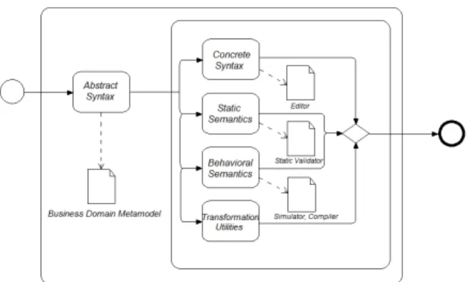
─ Business domain definition. To build tools
around a Business Domain, it is necessary to define the abstract syntax (AS) that expresses, structurally, all of its concepts and their relationships. This is typically done via the creation of a metamodel. Many languages and environments allowing the definition of an abstract syntax exist: Eclipse-EMF/Ecore (Budinsky, 2003), GME/MetaGME (Ledczi, 2001), AMMA/KM3 (Jouault, 2006), (KM3, 2005), Kermeta (Muller, 2005). All these are languages inspired by the object-oriented approach. These languages provide the concept of class to define the concepts of a DSML, classes are composed of properties. A property can be a reference when it is typed by another class or attribute when it is typed by a data type (e.g. integer, string...).
─ Concrete syntaxes definition. This step ensures
the expressiveness of the metamodel in terms of its objective. The concrete syntaxes (CS) of a language provide to user one or more formalisms, graphical and/or textual, to manipulate abstract syntax concepts and thus create instances i.e. models. Models thus obtained are conforming to the structure defined by the abstract syntax. The definition of a concrete syntax consists in defining a mapping MAC between the abstract syntax and the
concrete syntax MAC: AS↔CS and allows
annotating each of modeling language concepts in the abstract syntax defined by one or more decoration(s) of the concrete syntax and can be manipulated by the language user. Despite the wide choice in terms of devoted projects to the definition of concrete syntax mainly: GMF, Topcased, Obeo Designer…, there remain weaknesses in several aspects of such tools, which complicate this step. These problems motivate our research and they will be rose in subsection below.
─ Static semantics definition. This step defines in
this step, the axiomatic semantics that can be verified statically and expressed on the abstract syntax. This is done using the metamodeling language itself (e.g. multiplicities) or by adding constraints expressed by languages such as OCL. Indeed, this is to restrict the models allowed by these constraints.
─ Behavioral semantics definition. This step
consists on expressing the behavior expected from models. Several techniques are possible, either by interpretation (operational semantics) or by compilation (denotationnal semantics) (Jezequel, 2012). The choice of either of these techniques depends on the goals but also on the requirements in terms of performance and development time.
─ Transformation utilities definition. Once abstract syntax and semantics are defined, it is possible to use them automatically or semi-automatically through transformations. As examples, it is possible to do: refactoring, model analysis, model composition, translation to another domain, code generation, documentation generation, test generation… We have just seen the metamodeling process for the definition of the business domain tooling and building graphical editors for metamodels. Our approach is situated in relation to this process: The set of metamodels that we propose and its chain of transformation follow this metamodeling process. Our metamodels are not only intended for computer-friendly users, but also to other stakeholders (different actors of the metamodeling process), which aim to build their own modeling tools.
2.3 Evaluation Criteria
Two evaluation approaches were suggested by P. Mohagheghi and Ø. Haugen (Mohagheghi and Haugen, 2010):
Qualitative approaches cover case studies, analysis
of a language and the tool by experts for various characteristics, and monitoring or interviewing users.
For the quantitative evaluation, they identified several metrics (effort, understandability, Usability...etc). In our study we put a particular emphasis on the following evaluation criteria, which are most relevant for metamodeling process actors. For each criterion we propose some metrics to quantify this evaluation:
• Graphical expressiveness and completeness criteria: Can we represent all the notation
elements? Can we use the full range of visual variables (Ledeczi, 2001)? And what’s their complexity?
For the Graphical expressiveness we apply the Moody’s scale (Moody, 2009) to our context to measure this criterion; it consists in assess tool capability to represent the eight visual following variables: retinal variables (shape, texture, brightness, size and color) - planar variables (Horizontal position and Vertical position). For the Graphical completeness we assess the tools capability to represent all kinds of shapes weighted on a scale of 0 – graphs not presents (textual editors), 1 - minor graphical completeness, to 5 - strong graphical completeness.
• Tool building approaches: what are the
approaches used to describe the semantic and graphical parts of the editor? (e.g. Proprietary languages, standard language, open language…)
• Reusability: Can we reuse existing components/functionalities of our tool? The tool supports separation of concerns? The tool supports the components inheritance?
• Required resources criterion: How much Time
and effort (resources) are required to model, debug, and generate artifacts (Kennedy, 2004)? We may also add time and effort to understand models. The adequate metric unit for this criterion is the man-day unit. This measurement was done by a single researcher with a background in modeling field but not necessarily an expert of the evaluated tools.
• License nature criterion: what is the kind of
license required to use the tool? (Commercial, Proprietary, Open Source, Freeware…)
• Produced Artifacts criteria: what are characteristics of artifacts produced with the graphical editor?
o Artifact format: What kind of persistence
format of these models? (Open format, structured support, binary files…)
3 EVALUATION
The purpose of this section is to evaluate the graphical editors’ specification methods, by evaluating some of these tools/technologies, namely the IBM Rational Software Architect (RSA), the Generic Modeling Environment (GME), MetaEdit+ and the Graphical Modeling Framework (GMF). These tools are used on a large scale and have
notoriety in the MDE community; each one of these tools provides innovative concepts and methodologies in this field.
─ Graphical expressiveness and completeness:
According to (Moody, 2009), the visual expressiveness is defined as the number of visual variables used in a notation. The visual variables are: shape, texture, brightness, size, color and the planar positions (horizontal and vertical). The graphical completeness is defined by the capability to use fully the shape variable (the use of any kind of shapes: complex, composites, 2D/3D…). We evaluated the tools’ capacity to use the full range of these variables; MetaEdit+ and GMF are the only two tools that allowed reproducing visual notations with fidelity and flexibility. GMF required substantial additional programming. GME and RSA offered the least flexibility for this criterion.
─ Editors’ specification approaches: MetaEdit+,
GME and RSA are metamodeling-language-based tools, they force users to describe semantic concepts in particular languages: proprietary languages for MetaEdit+ and GME (GOPPRR, GME modeling paradigm), and a standard language for RSA (UML). For graphical description, MetaEdit+ and GME don’t allow the separation of concerns, so the user defines the graphical particularities in the proprietary language, and then registers the editor in the case of MetaEdit+ and GME or generate code for RSA. GMF is a model-based tool, it proposes to describe the semantics and graphics as separated models (which is well for reusability) and then users can generate editor’s code.
─ In term of reusability, several tools such as MetaEdit+ and GME have introduced description languages in order to reuse the specifications in these proprietary languages; the goal of such language is to support the reuse and maintenance of models. However, the use of these proprietary languages weakens specifications portability, adding different constraints of license nature. Other form of reuse exists in Tools based on UML profiles. Thanks to this mechanism, tools like IBM RSA or MagicDraw allow the reuse of UML concepts and their concrete syntaxes by extending their corresponding metaclasses: each concept is represented by the visual notation of
its associated metaclass. However, the use of such tools consists of using UML to define the field concept, which can sometimes be in contradiction with the MDE vision: The UML extension mechanism lacks the desirable precision and leads sometimes, to dangerous contortions to 'stay' in the UML world (Jezequel, 2012).
─ Separation of Concerns: Most of specification
methods mentioned above mixes concerns. The most common form of this mixture is that of form and content (visual representations and semantics). For example, in the case of diagram specification using GME or MetaEdit+, the tools allow creating the specific concepts and their associated representations in the same repository. This weakens the required loosely coupling relationship between semantic and graphic aspects. The same problem is observed with Obeo Designer, which allows associating graphical concepts to domain concepts, in the same model. Other form of concerns mixing is between the graphical vocabulary and grammar definition. Indeed, Most of the tools offering the separation of graphical part from semantic one, as GMF, TopCased and even standards like Diagram Definition (OMG, 2012), fail to separate the two graphical syntax concerns which, are vocabulary (shapes, colors, styles ...) and grammar (structure and composition of representations).
─ Required resources: All these tools require
some effort/time for learning the technology and for creating our use case editor. The editor creation and usage mechanism in MetaEdit+ is likely the easiest one among the four studied here. GMF followed by RSA are definitely the worsts.
─ License Nature: for this evaluation we have
chosen three commercial tools, a free tool and an open source one. We can distinguish that commercial tools have an advanced degree of maturity comparing to the others. For commercial tools, MetaEdit+ proposes the best quality/price ratio.
─ Artifact format: MetaEdit+ is based on a model
repository to save editors, this repository has a proprietary format, but the tool provides a web service interface for all external manipulation on it. As MetaEdit+, GME has a particular format of models persistence, the models produced by the GME editors are persisted on
binary files. All Eclipse-based tools, have an open format of files, which is based on XMI standard, in the case of RSA, there are some particular files, which are binary and other that depend to UML syntax.
The following table provides a quick overview of the strengths and weaknesses of each tool, proved by metrics presented in section 2. The details of this evaluation are available in (El kouhen, 2011).
Table 1: Comparison summary. IBM RSA GME MetaEdit GMF Graphical Expressiveness 8/8 2/8 5/8 8/8 Graphical Completeness 2/5 1/5 5/5 5/5 Specification Approach
UML MetaGME GOPPRR EMF
Reusability by Composition No No No No Reusability by Inheritance Yes No No No Separation of Concerns No No No No
Licence Nature Cial* freeware Cial* EPL*
Artefact Format
XMI Binary Repository XMI
*Cial: Commercial, EPL: Eclipse Public License
4
PROPOSAL: MID
MDE is a generative engineering form that leads to system code described at a high level of abstraction. In this context, we take advantage of the MDE to design and generate diagrams editors.
The aim of our work consists in meta-modeling graphical editors, we were inspired by what has been made in tools and technologies based on models like the GMF and TopCased, the basic concepts of component-based modeling as well as the theoretical concepts of visual representations (OMG Diagram
Definition). This work has resulted in our
meta-model called MID "Metameta-models for user Interfaces and Diagrams".
We divided editor’s meta-modeling process in several parts, each having a particular concern. Initially, we separate the content and the form of a diagram at a high level of abstraction (language level). The content (semantics) of a diagram is out of scope of our work, it is widely treated with tools and technologies like EMF/Ecore (Budinsky, 2003).
Therefore, we focused on the diagram form and its various concerns (always at the language level), which allowed us to separate the graphical
vocabulary (different variables of shape, color, size...) and graphical grammar that describes composition rules of visual representations. After, we have identified the mapping part between syntax and semantics. Our proposal focuses on the visual syntax and the mapping part: It specifically excludes semantic issues and sentence-level issues (instance level).
MID allows designing the modeling editors at a high level of abstraction, based on components concepts (encapsulation, interfacing ...) and graph concepts, these metamodels cover the vocabulary point of view for visual variables, the structural point of view for the content of the editors’ graphical components (visual grammar) and the behavioral point of view for event management of the various visual components and the binding part, which is the mapping between the syntax and the semantics. The behavioral point of view is out of scope of this article.
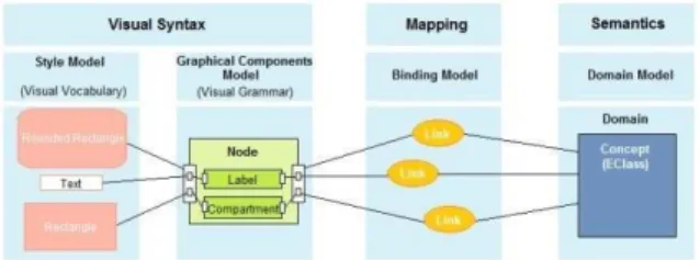
The Figure below shows the linkage of the involved artifacts (models described by Metamodels presented below). The binding model represents the mapping part between graphics and semantics. It’s composed of several bindings between each graphical component (via their domain interfaces) and its associated meaning (concept or proprietary).
Figure 3: MID: Involved Artifacts relationship
The graphical part is composed of two artifacts: structural model of graphical representations (visual grammar), which represents composition rules of visual symbols and the Style model (visual vocabulary), which defines information of visual variables. Example for such information are shapes, position, fore and background colors, gradient, visibility, line width as well as a line style.
Our approach offers many advantages and keeps its promises in terms of proposed criteria in the section 2:
In term of graphical expressiveness we offer the possibility to use the eight visual variables. For the graphical completeness, our metamodels allows adapting visual representations through the styles metamodel which offer a full range of basic visual notations, that we could compose, within the components approach, with each other to create
complex shapes. This two advantages help to customize specific domain modeling.
In term of reusability, we introduced a new concept, considering models as components. Models are theoretically more easily to understand and manipulate by business users, which correspond to the goal of the MDE. Components saves considerable gain of productivity through ease of maintenance, it allows better teamwork and helps for the industrialization of software developement. Consequently, we merge the inheritance mechanism known in the Object-oriented programming, and the encapsulation concept used in the components programming in our metamodels for an efficient reuse and overriding of components in different contexts.
We succeed to describe our metamodels according to the principle of the separation of concerns, with the interfacing between them (the communication between each concerns is done through interfaces) that offer the weak coupling in our framework.
The following table presents the evaluation of our tool according the same criteria presented in section 2.
Table 2: MID Evaluation. MID Graphical Expressiveness 8/8
Graphical Completeness 5/5 Specification Approach EMF Reusability by Composition Yes
Reusability by Inheritance Yes Separation of Concerns Yes
Licence Nature
Open-Source
Artefact Format XMI
5
CONCLUSIONS
In this article, we present an approach based on components modeling, which allows the easy specification of diagram graphical editors at a high level of abstraction, in order to model, reuse, assembly and generate code following the MDE approach. To define this metamodel, we focus on different required criteria and needs on graphical editors. For the specification of our metamodel "MID", we follow the metamodeling process to describe the basic graphical concepts, using the component approach for assembly/compose editors. This allows us to organize our metamodel in accordance with different concerns, to increase the reusability of the editors and to enjoy the benefits of the MDE paradigm as models verification/checking
and the ability to choose targets technologies through model transformation techniques.
In MID, we solve some problems identified in existing tools and methods on the industry as in the literature. For example, the specification at a high level of abstraction without the need for manual programmatic intervention, the separation of concerns, the graphical effectiveness and finally editors reusability which was among the major problematic of our research work.
Our approach, based on models and components (composition, encapsulation, inheritance ...) present many advantages. First, through the reuse of model: the models are theoretically more easily to understand and to manipulate by business users; which corresponds to a goal of the MDE. Secondly, this reuse saves considerable gain of productivity through ease of maintenance of components; it allows better teamwork and helps for the industrialization of software development.
Briefly, we can say that our approach opens a new way that shows promises for wider use of modeling tools and automatic generation of applications. Based on components, is set to become one of the major paradigms in software development. Compared to the current development technologies, the promises of this approach are large through the ability to create complex applications by assembling existing simple model/components fragments and especially the possibility for non-computer specialists, experts in their business domain, to create their own applications from a high-level description using an adapted formalism, easy to understand and manipulate for them.
REFERENCES
Budinsky, F., Steinberg, D. and Ellersick, R., Eclipse Modeling Framework: A Developer's Guide. Addison-Wesley Professional, 2003.
De Lara, J. and Vangheluwe, H. L., AToM3: A tool for
multi-formalism and meta-modeling. In Proceeding FASE-ETAPS, pages 174–188, 2002.
El kouhen, A., Dumoulin, C., Gérard, S., Boulet, P., Evaluation of Modeling Tools Adaptation, research report, http://hal.archives-ouvertes.fr/hal-00706701, 2011.
Ferguson, R., Parrington, N., Dunne, P., Archibald, J., Thompson, J., MetaMOOSE-an object-oriented framework for the construction of CASE tools, In Proceedings (CoSET'99) LA, May 1999.
INRIA ATLAS. KM3: Kernel MetaMetaModel. Technical report, LINA & INRIA, Nantes, August 2005. Jezequel, J.M., Combemale, B., Vojtisek, D., « Ingénierie
Dirigée par les Modèles : des concepts à la pratique » Editions ellipses 2012.
Jouault, F. and Bézivin, J., KM3: a DSL for metamodel specification. In Proceedings of the IFIP (FMOODS), volume 4037 of Lecture Notes in Computer Science, pages 171-185, 2006.
Kelly, S., Lyytinen, K. and Rossi, M., Meta Edit+: A Fully configurable Multi-User and Multi-Tool CASE Environment, in Proceedings of CAiSE'96, LNCS 1080, Springer-Verlag, Crete, Greece, May 1996. Kennedy, K., Koelbel, C. and Schreiber, R., Defining and
Measuring the Productivity of Programming Languages. International Journal of High Performance Computing Applications 18(4), 441–448, 2004.
Ledczi, A., Maroti, M., Bakay, A., Karsai, G., Garrett, J., Thomason, C., Nordstrom, G., Sprinkle, J. and Volgyesi, P., The Generic Modeling Environment. In Proceedings of the IEEE Workshop on Intelligent Signal Processing (WISP), Budapest, Hungary, 2001. Minas, M. and Viehstaedt, G., DiaGen: A Generator for
Diagram Editors Providing Direct Manipulation and Execution of Diagrams, Proceedings VL '95, 203-210 Sept. 1995.
Mohagheghi, P. and Haugen, Ø., Evaluating Domain-Specific Modelling Solutions, Advances in Conceptual Modeling – Applications and Challenges, Lecture Notes in Computer Science, Volume 6413, Pages 212-221, 2010.
Moody, D. L., The “Physics” of Notations: Toward a Scientific Basis for Constructing Visual Notations in Software Engineering. IEEE Trans. Software Eng. 35(6): 756-779, 2009.
Muller, P-A., Fleurey, F. and Jézéquel, J-M., Weaving executability into object-oriented meta-languages, Proceedings of MODELS/UML'2005, pages 264-278, Montego Bay, Jamaica, October 2005. Springer. OMG, July 2012. Diagram Definition (DD), version 1.0,
http://www.omg.org/spec/DD/.
Pohjonen, R., Metamodeling Made Easy – MetaEdit+ (Tool Demonstration), Lecture Notes in Computer Science, Generative Programming and Component Engineering, Pages 442-446, 2005.