Association EURATOM-CEA
Département de Recherches sur la Fusion Contrôlée
THESE
pour obtenir le grade de
DOCTEUR de l’UNIVERSITE de PROVENCE
discipline :
MECANIQUE ENERGETIQUE
présentée et soutenue publiquement par
Bertrand RENARD
le 18 septembre 2006
THERMO-HYDRAULIC BEHAVIOUR OF
DUAL CHANNEL SUPERCONDUCTING CABLE-IN-CONDUIT CONDUCTORS FOR ITER
COMPORTEMENT THERMO-HYDRAULIQUE DES SUPRACONDUCTEURS DE TYPE
CABLE-EN-CONDUIT À DOUBLE CANAL POUR ITER
JURY
Pr. Roger MARTIN IUSTI Marseille Président du jury
Dr. Chantal MEURIS CEA Saclay Rapporteur
Pr. Michel FEIDT UHP Nancy Rapporteur
Pr. Lounès TADRIST IUSTI Marseille Directeur de thèse
Dr. Jean-Luc DUCHATEAU CEA Cadarache Responsable CEA
Thermo-Hydraulic behaviour of
dual-channel superconducting Cable-In-Conduit Conductors for ITER
Abstract
In an effort to optimise the cryogenics of large superconducting coils for fusion applications (ITER), dual channel Cable-In-Conduit Conductors (CICC) are designed with a central channel spiral to provide low hydraulic resistance and faster helium circulation. The qualitative and economic rationale of the conductor central channel is here justified to limit the superconductor temperature increase, but brings more complexity to the conductor cooling characteristics. The pressure drop of spirals is experimentally evaluated in nitrogen and water and an explicit hydraulic friction model is proposed. Temperatures in the cable must be quantified to guarantee superconductor margin during coil operation under heat disturbance and set adequate inlet temperature. Analytical one-dimensional thermal models, in steady state and in transient, allow to better understand the thermal coupling of CICC central and annular channels. The measurement of a heat transfer characteristic space and time constants provides cross-checking experimental estimations of the internal thermal homogenisation. A simple explicit model of global interchannel heat exchange coefficient is proposed. The risk of thermosiphon between the two channels is considered since vertical portions of fusion coils are subject to gravity. The new hydraulic model, heat exchange model and gravitational risk ratio allow the thermohydraulic improvement of CICC central spirals.
Keywords: cable-in-conduit conductors, superconducting magnets, fusion, forced flow, spiral, heat transfer coefficient, heat exchanger, ITER
Comportement thermo-hydraulique des supraconducteurs de type
cable-en-conduit à double canal pour ITER
Résumé
Afin d’optimiser le contrôle cryogénique des aimants supraconducteurs pour la fusion (ITER), les conducteurs de type câble en conduit à double canal (CICC) comprennent un canal central qui assure une résistance hydraulique minimale et une circulation d’hélium rapide. Le canal central constitué d’une spirale limite la température des supraconducteurs, mais complique singulièrement le refroidissement du câble. Les pertes de charge de la spirale centrale sont évaluées en azote puis en eau pressurisée ; un modèle de frottement hydraulique est ainsi proposé. Les températures doivent être connues dans le câble, afin de garantir le fonctionnement des supraconducteurs sous charge thermique. Il est alors possible de définir les marges et de fixer la température d’entrée. Des modèles 1D analytiques en régime permanent et transitoire ont été développés afin de mieux comprendre le couplage thermique entre les canaux du CICC. La mesure des constantes caractéristiques d’espace et de temps fournit une évaluation expérimentale de l’homogénéisation thermique interne. Un modèle simple et explicite du coefficient d’échange intercanal est proposé. Le risque de thermosiphon existant entre les deux canaux dans les parties verticales des bobines de fusion est évalué grâce à un critère. Les nouveaux modèles hydrauliques, thermiques et le critère de risque de thermosiphon permettent l’amélioration thermo-hydraulique de la spirale centrale de CICC.
Thermohydraulisches Verhalten des Innengekühlten
Zweikanalrohrsupraleiterkabels für ITER
Kurzfassung
Um die Kryogen-Benutzung und -Kontrolle der Supraleitenden Großmagneten für die Kernfusion (ITER) zu optimieren, wurde der Zweikanalrohrsupraleiterkabel (CICC) mit einer zentralen Spirale entworfen. Der Zentralkanal soll einen minimalen hydraulischen Widerstand und einen schnellen Heliumverkehr gewährleisten, führt jedoch zu einer schwierigeren Abkühlung des Kabels. Das qualitative und ökonomische Grundprinzip der Leiterspirale wird hier durch die Begrenzung der Supraleitertemperatur gerechtfertigt. Der Druckabfall der zentralen Spirale wird experimentell am Stickstoff und danach am Druckwasser ausgewertet und daraus ein hydraulisches Modell vorgeschlagen. Die Temperaturen im Kabel müssen quantitativ bekannt sein, um Hitzestörungen des Supraleiters während des Betriebes der Spule zu verhindern, sowie um ausreichende Spielräume mit entsprechend niedriger Eintrittstemperatur einzustellen. Es wurden analytische eindimensionale Modelle entwickelt, um die thermische Kopplung zwischen den Kanälen des CICC im Dauer- und Übergangszustand besser zu verstehen. Die Messung der Raum- und Zeit-Konstanten liefert eine Versuchsbewertung der internen thermischen Homogenisierung. Es wird ein einfaches und ausdrückliches Modell des globalen Zwischenkanal-Wärmeaustauschkoeffizienten vorgeschlagen. Das bestehende Thermosiphonrisiko zwischen den zwei Kanälen bei vertikale Fusionsspulen verweist auf ein Kriterium. Das neue hydraulische Modell, das Wärmeaustauschmodell und das Kriterium des Thermosiphonrisikos erlauben schließlich die thermohydraulische Optimierung der Kabel-Zentralspirale.
Schlüsselwörter: Rohrsupraleiterkabel, Supraleitende Magneten, Kernfusion, gezwungen Fluß, Spirale, Wärmeübertragungkoeffizient, Wärmeaustauscher, ITER
Association EURATOM-CEA
Département de Recherches sur la Fusion Contrôlée Service Tokamak Exploitation et Pilotage
Groupe CRYomagnétisme F-13108 Saint Paul-lez-Durance
Acknowledgements
I want to pay a special tribute to my real Boss in heaven and to my parents for the best gift of all: life.
I would like to thank master Philippe Bévillard for his invaluable art, humble pedagogy, altruistic endeavor and communicative confidence.
In this work my warmest gratitude goes to my CEA advisor Jean-Luc Duchateau who was always smiling and focused in teaching and guiding my work step by step. For his in-depth criticism and advice on my research I have the pleasure to thank my Ph.D. director Lounès Tadrist.
I am particularly grateful in experimental aspects of my thesis to H. Cloez, J-P. Serriès and P. Decool. A special mention goes to D. Ciazynski for his fantabulous criticism, leading me to adopt stringent scientific methods. This work would not have been successful without the contribution of M. Boehler, L. Bottura, P. Bruzzone, N. Commaux, D. Henry, J-Y. Journeaux, B. Lacroix, C. Le Niliot, P. Libeyre, A. Martinez, S. Nicollet, B. Rousset, B. Stepanov, M. Tena, F. Topin and B. Turck.
For their help and support: J. Alduini, N. Abid, N. Arnavielhe, D. Balaguer, M-C. Bertrand, J-P. Bonnet, H. Bottolier, J-P. Boubert, M-C. Brieu, Y. Corre, N. Dolgetta, J. Duplat, N. Ehret, S. Girard, B. Glas, I. Graour, D. Gravier, C. Grisolia, L. Larchevèque, C-A. Lebailly, M. Leboisne, P. Lepargneux, J-L. Maréchal, R. Martin, M. Nicolas, C. Itan, A. Pillon, P. Prochet, J. Pullino, P. Reynaud, F. Rigollet, S. Sanchez, C. Sierra, H. Slavik, N. Snacel, N. Thomas, D. Van Houtte, J-V. Vidal, L. Zani, and to many more people from GCRY, STEP, DRFC, IUSTI and Polytech’ Marseille.
For their cheering support, my (choir) friends from Antequiem, Choeur Grégorien, Choeur ND de Joie, Choeur St Ephrem, ECP, Gaudete, Laudate Pueri, Offrandes Musicales, Pénitents gris, ICRSP Port-Marly, St Eugène-Ste Cécile.
This thesis was supported by CEA\INSTN. Experimental campaigns were funded by CEA/DSM/DRFC/STEP, CRPP/SULTAN, EFDA tasks M50 and CODES.
Table of content
Abstract ... 3 Résumé ... 3 Kurzfassung ... 4 Acknowledgements ... 5 Table of content ... 6Introduction on thermonuclear fusion and tokamaks ... 9
1 Dual channel Cable-In-Conduit Conductor ... 13
1.1 Conductors for fusion ... 13
1.1.1 Superconductivity ... 13
1.1.2 Superconducting strands ... 15
1.1.3 Superconducting conductors ... 16
1.2 Cooling systems ... 18
1.2.1 Heat loads and shields ... 18
1.2.2 Forced flow cooling loop and refrigerator ... 20
1.3 Dual Channel Cable-In-Conduit Conductors ... 22
1.3.1 Dual channel concept ... 22
1.3.2 Pressure drop reduction ... 24
1.3.3 Thermal imbalance ... 25
2 Pressure drop ... 27
2.1 Bundle region pressure drop ... 27
2.1.1 Existing models ... 27
2.1.2 Katheder model limits and uncertainty ... 28
2.1.3 Bundle pressure drop model improvement ... 31
2.2 Experimental spiral friction in nitrogen ... 33
2.2.1 Experimental campaign ... 33
2.2.2 Compressibility ... 35
2.2.3 Results and precision ... 39
2.3 Experimental spiral friction in water [Ren06-3] ... 41
2.3.1 Experimental campaign ... 41
2.3.2 Results ... 42
2.3.3 Precision ... 43
2.4 Friction factor model ... 45
2.4.1 Parameters driving turbulence ... 45
3 Interchannel heat exchange ... 57
3.1 Steady state analysis [Ren06-1] ... 57
3.1.1 Principle and hypothesis ... 57
3.1.2 Heat equation solution ... 58
3.1.3 Applications ... 60
3.2 Assessment of the heat transfer coefficient in steady state ... 61
3.2.1 Preliminary comments on experimental set-up ... 61
3.2.2 Measure of the heat transfer coefficient in water ... 64
3.2.3 Measure of the heat transfer coefficient H in cryogenic helium ... 69
3.3 Transient analysis [Ren06-2] ... 74
3.3.1 Principle and hypothesis ... 74
3.3.2 Heat equation solution ... 75
3.3.3 Application: Transition time τ ... 76
3.4 Assessment of the heat transfer coefficient H in transient ... 78
3.4.1 Transient experimental campaigns ... 78
3.4.2 Water transient applicability ... 79
3.4.3 Helium transient application ... 80
3.5 Heat transfer model ... 83
3.5.1 Unhomogeneous thermal resistances ... 83
3.5.2 Convection coefficients ... 85
4 Central channel spiral improvement ... 89
4.1 Danger of thermosiphon ... 89
4.1.1 The thermosiphon principle... 90
4.1.2 Evaluation of the risk ... 92
4.1.3 Thermosiphon risk in ITER coils ... 94
4.2 Design sensitivity to friction and heat transfer ... 95
4.2.1 Friction sensitivity to spiral design ... 96
4.2.2 Interchannel heat exchange sensitivity to spiral design ... 98
4.2.3 Wrappings ... 99
4.2.4 Central channel diameter and thickness ... 101
4.3 Optimal central channel proposal ... 102
4.3.1 Spiral improvement criteria ... 102
4.3.2 Proposal of spiral design ... 103
4.4 Other issues and alternative CICC design ... 104
4.4.1 Strands compression ... 104
4.4.2 Future investigations to optimise CICC thermohydraulics ... 106
Conclusions ... 107
Résumé détaillé : ... 109
1. Conducteurs de type Câble-en-conduit à double canal ... 110
2. Pertes de pression ... 115
3. Echange thermique ... 120
4. Dimensionnement de la spirale centrale ... 129
Appendix I: Test facility OTHELLO ... 134
Appendix II: Pressure drop measurements ... 135
Appendix III: Test facility HECOL ... 140
Appendix IV: Test facility SULTAN ... 143
Appendix V: Stationary thermal resolution ... 146
Appendix VI: Transient thermal resolution ... 151
Introduction on thermonuclear fusion and tokamaks
Since the industrial revolution in the XIXth century, the world population and the energy demand keep increasing. Today, the most important part of the power consumption comes from oil (~ 36%) but the world resources are limited and oil reserves exhaustion is predicted. Controlled fusion arises today as a solution which could supplant disappearing fossil energies (oil, coal). Research on fusion undertaken since nearly 50 years have led to the construction of large instruments intended to produce reactions of fusion, through the magnetic confinement of hot plasmas.
Since 1988, the Research Department of Controlled Fusion (or DRFC) ensures the operation of a Tokamak (Tore Supra) for scientific research. For this type of machine, the confinement of plasma is ensured by a magnetic field created by coils. Their design with coils using superconductivity reduces considerably the heat losses thus lowering the operating costs of the reactor.
Research on controlled fusion is presently dominated by the next establishment of the International Thermonuclear Experimental Reactor (ITER) in Cadarache. To design and build this machine, very specific research actions are carried out by CEA in DRFC. One of the major topics investigated for several years is related to the design of superconductor cables constituting the magnetic system of ITER.
Thermonuclear fusion
Two types of nuclear reactions make it possible to produce energy on a large scale:
• Fission, which consists in breaking a heavy nucleus by bombarding it with particles. A breaking nucleus produces energy and particles, which in turn travel and break other heavy nuclei, in a chain reaction. The atomic fission of uranium is used in the nuclear power plants.
• Fusion, which consists in combining two light nuclei to form a larger one and to release energy.
To fuse, the nuclei must overcome their natural repulsion. This is possible when the matter is brought up to very high temperatures (several tens of million degrees). The atoms are then separated in fundamental components: electrons and nuclei. They form a hot gas called plasma.
Although any random pair of light nuclei can fuse, the most accessible reaction is between deuterium and tritium (isotopes of hydrogen). Deuterium is very abundant and inexpensive. However tritium does not exist in nature. It is a strongly radioactive gas which can be produced from lithium.
To confine a plasma and obtain the level of density necessary to the reaction, either a magnetic or an inertial confinement is used.
Magnetic confinement
Plasma is confined in an immaterial box with a torus shape (Tokamak, Stellarator), created by magnetic fields. The density is low (10-5 times that of the air) but the plasma confinement time is “high” (a few seconds).
Tokamaks
Several types of magnetic boxes exist; the most powerful is called Tokamak, and was invented by the Russians in the fifties. It is the most studied and promising research path for
To trap the particle, the field line is closed on itself. The particle radius of gyration (Larmor radius) depends on the magnetic field intensity, on the mass and electric charge of the particle, and on its energy. The more powerful the magnetic field, the smaller the Larmor radius, the particle remaining in the vicinity of the field line. Electrons, much lighter than ions, have a smaller Larmor radius for the same energy. High energy particles have a larger Larmor radius than lower energy particles, and are thus more difficult to confine. The Larmor radius typically ranges from a few millimetres to a few centimetres.
In this basic configuration, the direction of the magnetic field is purely toroidal. Unfortunately, on a simple circular trajectory of this type, the particle undergoes a slow transverse drift, caused by the gradient of magnetic field and the centrifugal force, and whose direction depends on the electric charge sign. For example, ions will derive upwards (Figure 0-1).
Figure 0-1: Ion drift in a tokamak, related to the magnetic field
To compensate for this undesirable effect, the configuration is stabilized by adding a poloidal component to the toroidal field. It is the magnetic configuration used in the tokamaks. The field lines become helices rolled up around torus surfaces encased in each other, called magnetic surfaces (Figure 0-2).
Figure 0-2: Trajectory resulting from the toroidal and poloidal magnetic field components The particle passes half of its time “head up”, and the other half “head down” (Figure ). The effect of the drift is compensated on average and particles remain confined close to their magnetic surface with a helicoid trajectory around the lines of already helical field.
In tokamaks, the toroidal magnetic field is generated by external coils, while the poloidal magnetic field is induced by a current circulating in the plasma. The plasma current is itself generated as the secondary of a transformer.
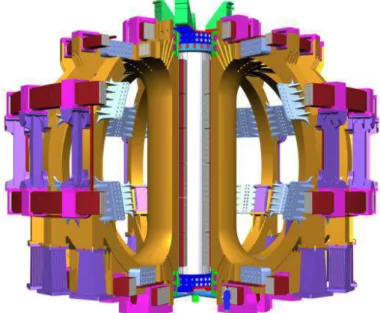
Figure 0-3: ITER magnetic configuration for plasma confinement (courtesy of ITER)
The ITER project
Thanks to remarkable results obtained these last years, the international research and engineering community is ready for further studies on magnetic controlled fusion. The next step is to demonstrate maintained combustion of a deuterium-tritium plasma over long times. It is the principal objective of the tokamak ITER, the next reactor to be built and operated in the framework of a world collaboration joining together countries which have been taking part for years in the fusion research program.
ITER (Figure 0-3) will be a superconducting tokamak of the largest size ever built. Tore Supra, a CEA superconducting tokamak has demonstrated on the long run since 1988, that superconductivity was not a technological obstacle for fusion. This technology gives access to long duration plasma discharges.
The principal objective of ITER is the study of plasmas in combustion, i.e. of plasmas where the proportion of self heating from fusion reactions exceeds 60%. The proportion of nuclear heating hardly ever reached 10% in the best discharges carried out in JET (Joint European Torus).
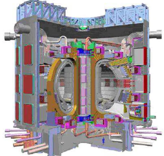
ITER will be the first machine integrating the majority of technologies necessary to the preparation of a sustainable fusion reactor: superconductivity, plasma-facing components, tritium layers, robotics and diagnostics (Figure 0-4).
ITER is a technological challenge in all fields, and particularly in the field of super-conductivity. Its characteristics are rather impressive and prove the ambition of the project. The major radius of the plasma will be 6.2 m and the minor radius of the plasma is 2 m. Confinement will be ensured by a toroidal field of 5.3 teslas, a plasma current of 15 MA. The current of the Toroidal Field (TF) system is 80 kA. Superconducting magnets and cryogenic facilities represent over a third of the construction investment cost of the machine.
Figure 0-4: Diagram cut of ITER, with a man in blue at bottom, represented for scale (courtesy of ITER)
Coils superconducting conductors require cryogenic cooling. The International Thermonuclear Experimental Reactor (ITER) project has triggered considerable work in the technologies of superconductor cryogenics, in the magnets themselves and in their supercritical helium supply networks. These conductor development programs are a source of input for a better understanding of CICC, applicable to any large magnet with high field (>5 T).
The aim of this thesis is to study and improve the thermohydraulic behaviour of the supercritical helium flow in the dual channel superconducting cable-in-conduit conductors constituting ITER coils.
1
Dual channel Cable-In-Conduit Conductor
1.1 Conductors for fusion
Since 15 years an important activity has been initiated in Cable-In-Conduit-Conductors (CICC). This activity is mainly related to fusion. In this domain, the sizes of the machines push to high current conductors, and high voltages during protection phases when the magnet must be rapidly deenergised [Weg02, Duc02].
The design of high current and high field conductors for fusion application has evolved to the present solution consisting in CICCs characterised by a steel jacket, an external electrical insulation, and forced flow cryogenic cooling.
The need of thermohydraulic design and optimisation of dual channel CICC has led to the construction of numerous full size cable samples, joint samples and prototypes called model coils. In the framework of the ITER preparation, a Poloidal Field Insert Coil is programmed for testing in Naka (Japan).
1.1.1 Superconductivity
History
In 1911, H. Kammmerling Onnes, which had successfully liquefied helium three years earlier, observed with G. Holst that the electrical resistance of mercury is null at very low temperature. This behaviour is contradictory with the Joule effect. Indeed when current circulates in a conducting material, losses cause heating of this conductor. These losses are proportional to the material resistance and to the square of the current. They become very important for high currents and thus large magnets.
In the case of superconductors, and even if it is impossible to assert that it is strictly null, resistivity becomes very weak (below 10-25 Ωm). This behaviour is the demonstration of a quantum effect. The resistivity being negligible, the losses by Joule effect are extremely weak. However these remarkable properties appear only for relatively low temperatures. The principal materials industrially available, like niobium-titanium and niobium-tin, must be cooled by liquid helium to 4.2 K to become superconducting.
Among superconductors, a singular class of materials was discovered in 1986 and is called “high critical temperature superconductors”. It gave birth to many hopes for a wider application of superconductivity. The weak current transport properties and extreme complexity and brittleness of these materials are still handicapping factors for short-term applications.
Critical parameters
• Critical field BcThere is a critical magnetic field Bc above which the material is not superconducting. • Critical temperature Tc
There is a critical temperature Tc above which the material loses the property of superconductivity. This temperature is very low, near the absolute zero. It is lower than 23 K for conventional materials and around 100 K for high critical temperature superconductors. • Critical current density J
The current density circulating in a superconducting material has a defined value which is the critical current density Jc. Jc is a function of the field, of the temperature, and for some materials of the strain.
• Mechanical constraint
For some material, the critical parameters (Bc, Tc, Jc) are sensitive to the mechanical deformations (traction/compression). Mechanical constraints are not seen as a limit, but as a possible degradation of superconducting conductors performance.
Two types of superconductivity exist: type I and type II. Practically, only type II superconductors are used to produce magnetic fields in coils [Wilson]. A characteristic curve of type II superconductor can be well approximated in terms of electric field (E) and of current density (J) by:
n c c J J E E = (1.1-1)
Ec et Jc are respectively the critical electric field and the current density. Ec is equal to 10-5 /m by convention.
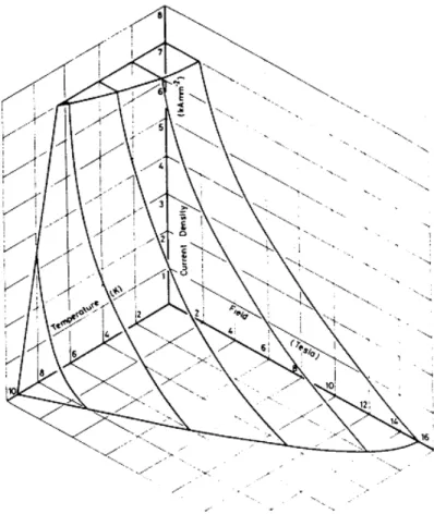
Figure 1-1: Niobium-Titanium critical surface superconducting state under the surface Jc = f(T, B)
Critical surface
Critical field Bc, critical temperature Tc and critical current density Jc are thus the three parameters which limit the transport of current by superconductivity. These values are connected and define a critical surface (Figure 1-1) in the space (B, T, J). If one of these three parameters is exceeded, the material loses its superconducting state. It is therefore very important to control temperature through cryogenic cooling [Tix95].
1.1.2 Superconducting strands
Superconductors and strands: The materials most largely used for the manufacture of magnets are alloys containing niobium. Two main families exist:
• Alloys containing niobium and titanium • Alloys containing niobium and tin
Niobium-titanium alloys
Niobium-titanium (NbTi) today is the most used and the least expensive among the superconducting materials. This material can be used for producing magnetic fields up to 11 T at 1.8 K. One of its greatest advantage is ductility. Niobium-titanium can thus be drawn into strands, twisted and cabled without degradation of the critical current due to mechanical constraints. Moreover, niobium-titanium strands do not require an elaborate heat treatment. A copper crown is always placed around the niobium-titanium strands.
The role of copper is to limit the heating in the event of a loss of superconductivity. In this case, the resistivity of the superconductor becomes very large and the current can temporarily redistribute into copper. It is also used to improve the thermal stability of the system thanks to a better thermal coupling of the superconducting strand heart with the coolant.
The magnets of TORE SUPRA use niobium-titanium cooled at 1.8 K. However for an operating temperature equal or higher to 4.2 K, the maximum field accepted with a sufficient safety margin cannot exceed 6 T [Lib05-1]. This is why this material is bound in ITER to the low field coils in the Poloidal Field (PF) system.
Niobium-tin alloys
Niobium-tin (Nb3Sn) presents a critical field Bc higher than that of niobium-titanium: about 23 T at 4,2 K for pure niobium-tin and about 29 T for niobium-tin with titanium and tantalum additions.
This superconductor is fragile and a mechanical tension of more than 0.5% can irreversibly damage the strands. Strands manufacture (wire drawing, twisting, cabling and winding) must be carried out in strands in which the phase niobium-tin is not yet formed. A heat treatment is then carried out, the purpose of which is to carry out the diffusion of tin allowing the formation of the final superconducting compound. Heat treatment at temperatures of about 650°C lasts approximately three weeks, independently of the object size and mass.
Figure 1-2: Section of an internal tin niobium-tin strand produced by Europa Metalli (courtesy of Europa Metalli)
Two main different methods to manufacture these alloys are available. The first is known as “bronze method”. The elementary strand is composed of microscopic niobium filaments inserted in a bronze matrix. Tin confined in bronze diffuses in niobium during heat treatment.
This type of superconductor will be used for the high field coils of ITER (12-13 T). These coils are the toroidal field coils (TF) and the central solenoid (CS).
Copper is present for electrical and thermal stability in superconducting strands, but additional copper strands can be added to ensure protection in the event of transition to the normal state.
1.1.3 Superconducting conductors
Conductors used in fusion magnets
The Cable-In-Conduit-Conductors (CICC) of the project ITER are circular cables made up of a great number of superconducting strands (Ø ~ 0.81 mm) twisted in successive stages. The strands are drawn inside a jacket in which the supercritical helium coolant circulates [Tur93]. These cables have the following advantages:
• high transport current up to 70 kA
• circular symmetry favourable to even current distribution • efficient local strands cooling by the helium circulation • low magnetic losses in variable magnetic field
• easy external electric insulation (similar to that of a warm conductor)
• easy manufacture of the conductor by cable drawing through the stainless steel jacket Forced flow conductors are well adapted to large fusion magnets. Indeed, their built-in steel jacket insulation installed around the conductor itself is better adapted to high voltage operations than the conventional bath cooled conductors [Rou97], more sensitive to short circuits [Lib05-1]. In addition, in operation these magnets are subject to heat deposition of different kinds which can be better removed by helium circulation. However, practically no magnets with use of CICC design is yet in operation today except the NbTi magnet of the Poloidal Field (PF) system of the LHD Torsatron in Japan [Sat00].
Nonetheless, the first plasmas of several machines equipped with magnets systems of this kind are shortly scheduled: SST1(India) and EAST (China) in 2005, KSTAR (Korea) in 2007, W7-X (Germany) in 2010, whose conductor cross-section is presented in Figure 1-3.
Figure 1-3: CICC cross-section of stellarator W7-X (courtesy of CEA/DAPNIA) The trajectories followed by strands are helices rolled up around each other. The shape of the helical trajectories is controlled by two principal parameters: the twisting length L and the rolling radius R. There is a twisting length and rolling radius at each stage.
The structure of a cable in conduit can thus be described using the following parameters [Duc02, Bes98]:
• stages
• twisting length
The different levels of cable manufacture are called stages (see Figure 1-4). The first stage is obtained by twisting a defined number of strands. The second stage is obtained by twisting a defined number of units of the first stage and so on. For example, for a cable-in-conduit of the type [3 3 5 4 6], the first stage is made of three twisted strands: a triplet.
strand Triplet (stage 1) Triplet of triplets (stage 2)
Quintuplet of triplets of triplets (stage3) Petal (stage 4)
Figure 1-4: Manufacture of the different conductor stages of a superconducting petal The second stage consists in the twisting of three triplets. The third stage is obtained by twisting five triplets of triplets. The last but one stage is called petal. It is insulated and protected by a stainless ribbon called wrapping.
1.2 Cooling systems
Because superconductors are sensitive to temperature [Zani04], the heat load falling on the magnets must be carefully evaluated in order to propose an effective cooling system.
1.2.1 Heat loads and shields
Heat load P
hlto the magnet system at 4.5 K
When the superconducting magnet system is at low temperature, heat coming from different sources is deposited. We will not enter into details about the different sources but classically one can identify in a fusion tokamak TF system (ITER):
• ac and eddy current losses in the winding, cases, and structures of the system (7.29 kW on average)
• heat loads due to current leads (~1 kW)
• residual nuclear heating escaping through the neutron shielding
• resistive joint losses in the magnets and static losses due to thermal radiation from thermal shields and thermal conduction through gravity supports and connections (11.9 kW) The two first categories of heat sources are located in the metallic parts of the CICC (Figure 1-5). Nuclear radiation falls in all metallic volumes, preferentially on the row of conductors closest to the plasma. Static losses fall on the periphery of the magnet and can be partially removed by a helium circulation outside the magnetic system. These heat sources cannot be deflated: they constitute the imposed working conditions from the cryogenic viewpoint.
Figure 1-5: Cut of a TF coil inner leg; conductors are dark rings; thermal and neutronic shields are on the right, facing the plasma; the keystone shape allows to lean on other coils.
Mitigation of AC losses
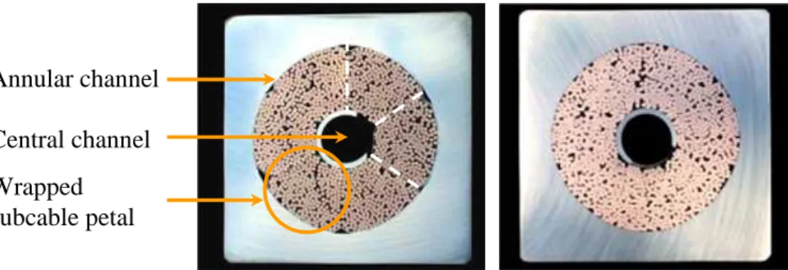
0.055 mm thick stainless steel tape wrappings around the petals are meant to reduce the intensity of the eddy currents created by the AC field, and the generated heat. The Poloidal Field Insert Sample (PFIS) presented in upcoming section 1.3 is made of two asymmetric conductor legs, where the superconducting strand petals are wrapped in stainless steel with 80% coverage in the left leg, whereas on the right leg the subcable petals have been stripped of their wrappings before insertion in the jacket, itself compressed to reach a similar void fraction [Hur05]. The purpose of this asymmetry of the sample wrappings is to evaluate current recirculation minimization within the cable, and the thermohydraulic influence of wrappings.
In ITER the plasma neutronic fusion power (~500 MW) is shielded by shielding modules and the vacuum vessel, cooled by pressurised water, presented in Figure 1-6. Thus only the residual neutronic power reaches the TF coil system which surrounds the vacuum vessel (~10 kW instantaneous and 3 kW in average for a 500 s plasma discharge every 1800 s).
Figure 1-6: Cut view of the shields: plasma in the center; actively cooled plasma facing components and divertor (bottom); inside the vacuum vessel; coils outside (courtesy of ITER)
Thermal shield system
A complex system of thermal shields prevents heat radiation coming from the cryostat (upper CTS cylinder, central CTS etc.) and from the vacuum vessel (VVTS) from falling on the coils at 5 K (Figure 1-7). These thermal shields are cooled at 80 K. Heat radiation from 80 K to 5 K is evacuated by the circulating helium loop.
Vacuum vessel Shielding modules
Figure 1-7: Thermal shields (TS) and coils position (TF, PF and CS) in ITER elevation view (courtesy of ITER)
1.2.2 Forced flow cooling loop and refrigerator
The heat load from all sources Phl is removed from the coils to keep the temperature constant by circulating a mass flow through the conductor. This circulation requires a pump work to compensate the viscous pressure losses, and associated cryogenic power Pcirc (11.4 kW). The electrical power associated with this cryogenic power is high: about 2.9 MW for the entire cryogenic circulation system of ITER (TF, PF and CS).
The aim of the thesis is to optimise the Cable-In-Conduit to reduce this power without affecting the superconducting strands temperature.
circ circ circ P m P η ρ. . . ∆ = (1.2-1) .
m/ρ being the volumetric flow circulated in the conductors and ∆Pcirc the pressure variation forced by the helium circulating pumps, affected by the efficiency ηcirc.
The two main sources of heat loads on the 4.5 K refrigeration cold system are Phl and Pcirc, itself a direct function of Phl because the mass flow rate
.
m is chosen in proportion to the power to be removed, to keep superconductor temperature margins constant. Pcirc is also related to the design of the magnet conductor and associated pressure drop characteristics (see Figure 1-8).
Figure 1-8: Cryogenic loops and circulation pressure drop in ITER expected design A minimal mass flow rate is defined for each operation scenario to safely and actively evacuate heat load in the secondary loop. During plasma operation, the level of heat losses in the multi-strands ITER TF cable (1000-1500 strands) imposes a minimal mass flow of 8×10⁻³ kg.s-1 to safely remove the energy at the nominal temperature of 4.7 K and with a pressure drop of 0.06 to 0.1 MPa [ITER05].
Coils are divided into double-pancakes with conductors of ~700 m, the unit length of the conductor. To minimise the length of the channel used by the coolant, helium inlets are placed through the jacket, in the middle of the pancake conductor length. Helium flows in opposite directions from the middle to the electric joints at each end. The ITER TF system is constituted of 18 coils each made of 14 pancakes 380 m long.
The ideal place for the inlet of each pancake is in fact the hydraulic –not geometric– center of the conductor. This ideal positioning of helium inlets would require a hydraulic qualification of each pancake in both flow direction before the inlets are manufactured, in order to check that pressure drop is symmetrical, and to correct it if necessary.
Hydraulic acceptance tests performed on W7-X conductors unit lengths show discrepancies of up to +/- 20% in mass flow rate, with a normalised room temperature helium inlet pressure of 2 MPa and an outlet pressure of 0.1 MPa. It is likely that ITER pancakes will also have hydraulic resistance differences. It is expected that these hydraulic resistance differences could be lower than in W7-X due to the presence of a central channel (section 1.3).
For each helium distribution satellite, the most resistive pancake imposes the helium distribution pressure, to obtain the minimum nominal mass flow rate min
.
m . From this fixed pumping pressure, the various pancakes may have various mass flow rates min
.
m
≥ . The pump work Pcirc is proportional to total mass flow rate cumulating that of each pancake
min . . . m n m m n i i ≥ × =
∑
=11.3 Dual Channel Cable-In-Conduit Conductors
In order to reduce conductor friction pressure drop, the strands are twisted around a spiral delimiting a low impedance central channel. The dual channel cable-in-conduit conductor (CICC) originally developed at CEA for high current superconducting magnets [Bes92] has now been selected for the International Thermonuclear Experimental Reactor (ITER) coils. The main advantage of this conductor is to provide a low hydraulic resistance as well as a temperature rise limitation [Duc02]. The low impedance central channel consisting of a stainless steel spiral pipe has a premium role in the distribution of mass flows and in the global pressure drop.
1.3.1 Dual channel concept
In certain cases, when the size of the system is very large, there is interest to use a special sort of cable in conduit: the so-called dual channel CICC, to minimize pressure drop and the associated cold power related to helium circulation. In this type of conductor, two channels are offered to helium transit: a central channel and the bundle region where strands are situated (see Figure 1-9). Two parallel hydraulic channels minimize the pressure drop for the necessary helium flow. Indeed a pressure drop at low temperature is highly expensive in terms of the cryogenic power consumed to recover the helium enthalpy change introduced by the loop circulating pumps. Heat loads are efficiently removed with a moderate pressure drop thanks to the central channel, which serves as an internal heat exchanger inside the conductor.
Figure 1-9: Cross-section of ITER Poloidal Field Insert Sample CICC with wrappings (W) left leg (L) and without wrappings (NW) right leg (R)
The design choices for this central channel have an important impact on the hydraulics, pressure drop and flow repartition, consequently influencing economical aspects of the project. Optimisation of forced flow conductor cooling [Raf03, Tad04] is best illustrated in the International Thermonuclear Experimental Reactor project (ITER). Experience about CICC electric and thermohydraulic behaviour has been accumulated but mainly in the tests of numerous prototypes called model coils. The conductor cross-sections of ITER PF insert samples are presented in Figure 1-9.
Wrapped subcable petal Central channel Annular channel
Figure 1-10: Burst representation of a cable in conduit with its six petals
The central channel is materialised by a spiral to maintain its diameter and guarantee that strands from the petals –even if cut– do not choke up the free-flow channel. The central spiral has a mechanical role when the conductor is under magnetic pressure forces.
Twisting the strands in six petals (Figure 1-10) around a low impedance central channel delimited by a loose spiral adds complexity to the geometry of strands and current redistribution in the conductor. Figure 1-11 illustrates the complexity of strands trajectories in a petal. The determination of these trajectories, associated to a local magnetic field calculation, makes it possible to evaluate in a realistic way the variation of the local electric field along the conductor. It is however not thoughtful to envision calculating the hydraulic resistance from detailed strands trajectories.
Figure 1-11: Strands Trajectories in a petal on a conductor PF twist length, with local zoom The use of dual channel CICC is considered at present time in the case of the ITER project, but the possibility of application is interesting for any large magnet with high field. Its most critical use is illustrated on the Toroidal Field (TF) system of this machine, which is the
1.3.2 Pressure drop reduction
The purpose of the central channel is to ease helium circulation by reducing pressure drop. The presence and geometry of a central channel strongly affects the global hydraulic pressure drop along the CICC unit length. The mass flow repartition is obtained with the hydraulic balance of pressure drop in both channels. A high variability was measured on strands bundle cable pressure drops; the central channel is expected to drive pressure drop and reduce cable hydraulic variability. The conductors studied are coil samples of ITER R&D programs prototypes.
Taking into account the level of TF coils heat loads, an isothermal helium mass flow rate of 8 g/s is a minimum needed to safely remove the energy from each individual pancake length. Comparisons of Table 1-1 are based on pressure drop measurements on spirals performed at CEA under a European contract [Nic02CODES], and on calculated projections. Based on these first results, it is possible to show that the impact of the central channel design is large on a project like ITER. Table 1-1 demonstrates that the optimisation of ITER CICCs has the potential to bring significant cryogenic cost reduction thanks to the central channel.
Table 1-1: Calculated comparison of conductors properties for different choices of central channel for the ITER TF system only.
ITER TF conductor projections with various central channels 0.6 MPa, 5 K, 8 g/s, 1400 strands, void = 0.332
Spiral 7/9 mm Perfor 50% ITER reference Spiral 7/9 mm Perfor 28% Smooth tube 7/9 mm Smaller cable without central channel Central channel friction coefficient 0.12 0.057 0.017 ∞ Mass flow distribution 5,1 g/s (annulus) 2,9 g/s (center) 4,2 g/s (annulus) 3,8 g/s (center) 3.5 g/s (annulus) 4.5 g/s (center) 8 g/s (strands, homogeneous) Pressure drop (380 m) 0,9956×10⁵ Pa 0.77×10⁵ Pa 0.58×10⁵ Pa 1.9×10⁵ Pa Cryogenic power required for TF He recompression 2,6 kW 2.0 kW 1.53 kW 5.15 kW Electric power of TF refrigerator 650 kW 500 kW 382 kW 1.288 MW Refrigerator investment cost 1.56 M€ 1.2 M€ 0.92 M€ 3.1 M€ Operating cost over 20 years; 0.86 M€ 0.67 M€ 0.5 M€ 1.7 M€
The pressure drop across a pancake is calculated neglecting singular pressure drops at inlet and outlet as well as mandatory design and manufacturing margins. An isentropic pump and an isobaric heat exchanger fight the isenthalpic pressure drop along the cable. The pump work is obtained from the fluid enthalpy variation with an efficiency of 0.6 (see equation (1.2-1)). In order to transform this work into cryogenic electrical consumption, the power is affected by the refrigerator global efficiency ηcryo:
1
. ≈
= fη
with the Carnot efficiency 2 1 T T Carnot − =
η and the quality factor f =0.25 at 4.5 K
Finally, cost assumptions include 40 000 hours of operation at nominal power in a 20 years machine life-span, cryogenic power investment 600 k€/kWcryo (over 10 kW) and operating cost 33 €/MWh.
The worst situation is obtained when there is no central channel, where Pcirc reaches the largest value of 5.15 kW. However, there would be a gain in the cable dimensions in this case, because the void in the superconducting strands must be kept constant for electrical and mechanical reasons.
Many concept and technology aspects of these forced flow cooling channels require deeper understanding, both in satisfactory levels of performance and in detailed physical processes. Spirals thermal properties including mass exchange between central and annular channels can only be assessed in a full CICC sample, where many parameters interfere.
1.3.3 Thermal imbalance
Though CICCs are meant to be as compact as possible, a central channel is self-justified as it reduces the circulation pressure drop, which therefore consumes less cryogenic power, hence reduces plant investment and operating costs. The design choices for this central channel have an important impact on the hydraulics –pressure drop and flow repartition– consequently influencing Reynolds, Prandtl, convection coefficients and thermal response of the cable. But the thermal inhomogeneity in the double helium flow within the cable brings complexity and a difference of temperature between central and annular channels under heat load. This leads to an increased temperature of the superconducting strands under heat load or unsteady cooling. An increased temperature in the heated strands reduces the superconductor temperature margin, as compared to an isothermal conductor with perfect transverse heat transfer.
Good thermal coupling allows helium circulating at higher velocity in the thermal exchanger central channel to efficiently extract power from the annular channel and keep the interchannel temperature difference low.
Assuming uniform central and annular CICC temperatures, a double channel conductor can be characterised by its annular (TA) and central (TC) temperatures only. This bithermal assumption allows to work with a 1D model of the CICCs. (Figure 1-12).
Figure 1-12: Propagation of a heat front: Longitudinal section of a double channel CICC, showing the annular and central temperatures TA & TC,
the annular and central mass flow rates mA & mC.
Additionally to the temperature difference (TA-TC), the difference in velocity induces a TC(x,t) TA(x,t) A
m
. t= 0 1 2 3 1 2 3 Cm
. TA(x,t) x(steady state and transient, for scenarii of heat depositions in the jacket and annular channel). The testing of CICC samples and model coils has brought evidence of a complex thermal behaviour.
The use of superconductivity for magnetic confinement fusion, as in the reactor ITER, requires a close evaluation, understanding and optimisation of thermal exchanges to maintain all superconducting strands under a sufficiently low temperature, especially during transients occurring for the reactor operation.
Literature thermohydraulic studies of rib-roughened high turbulence flows set aside work conducted in laminar, two-phase and phase change flows. Interesting studies include singular shape tubes [Cha00, Che01], square sections [Met90, Lio92], surfaces [Lew75, Han78, Tak96], internally finned tubes or inserts [Bos95, Man95, Liu01, Sar01], diaphragms in circular sections [Web71, Kim03] and rounded roughness in circular sections [Wei90, Pan93, Lon95, Vic04]. Spiral-like square roughness in circular section studies are applied to non-permeable heat exchangers where turbulence is promoted through added roughness with small turns and large gaps [Nun56, Gee80, Fir81]. On the contrary, CICC central channel spirals have a mechanical role hence large turns and smaller gaps.
Thesis content
Energetic studies about cryogenic fluid flow in a complex environment (porosity, turbulence), and thermal exchanges between coolant and superconducting strands (transfer and transport physics) are necessary to ensure a proper dimensioning of superconducting CICCs, of their dedicated cryogenic system, and to guarantee the nominal working properties of large-scale magnetic coils.
In this chapter, we have seen that the superconducting CICCs projected and developed in ITER possess two parallel channels: a low pressure-drop central channel delimited by a spiral, and an annular channel containing the superconducting strands. The dual channel conductor allows a more efficient cooling of the superconducting coils in a tokamak such as ITER. In order to further optimise the central channel spiral design, this thesis attempts to study in detail the thermo-hydraulic behaviour of spirals: the objectives are to better understand CICC thermo-hydraulics, to guarantee a correct cooling of the superconducting strands, and to provide dimensioning feed-in for the cryogenic systems and refrigerator.
In chapter 2 the central channel spiral pressure drop database is increased and in-depth friction study leads to a new pressure drop model, which was developed in the framework of this thesis [Ren06-3].
Two experimental methodologies of steady state [Ren06-1] and transient [Ren06-2] types for CICC thermal testing are developed in chapter 3, and lead to a thermal model for the heat transfer coefficient between the two channels.
Benefiting from the above original contributions, chapter 4 concludes by proposing an improvement of the ITER CICC design.
2
Pressure drop
Pressure drop, obeying a different law in each channel, equilibrates in these parallel channels. Spiral pressure drop is strongly dependant on geometric characteristics, because of their complex influence on turbulence.
Experimental pressure drop data are here studied and modelled in order to find a thermo-hydraulic optimum reduction of friction forces. Work first starts with friction because thermal properties are subordinate to hydraulics patterns.
In this chapter hydraulic models for the annular channel are first depicted (2.1), then experimental campaigns for investigation of pressure drop in the central channel spirals in pressurised nitrogen (2.2) and water (2.3) are detailed. Finally a pressure drop model is elaborated (2.4).
2.1 Bundle region pressure drop
Annular channel geometry –twisted strands, size of strands, void fraction– is dependant on electrical and mechanical constraints. The void fraction of superconducting strands petals is therefore considered fixed, and no thermohydraulic optimisation is sought on the annular channel geometry. Nonetheless, the annular channel geometry drives the pressure drop in the bundle. It is necessary to have a hydraulic model in the annular channel in order to solve the full CICC hydraulic law.
2.1.1 Existing models
Calculated central and annular pressure drops are balanced in order to obtain the mass flow repartition in the cable. An error on annular pressure drop automatically implies an error on the ratio αA =m.A m. and introduces uncertainty on heat transfer and the whole thermohydraulic characteristics of the conductor. A study of CICC central channel cannot omit the understanding of annular hydraulics.
Porous medium model
The annular channel is an anisotropic permeable medium split into solid superconducting strands and pores, through which the fluid flows. Porous media have a fine structure, and the detailed flow around each element of the fine structure is typically not considered, but only mean flow properties are necessary. A porous medium can be described by a hydraulic law using a permeability, such as the Darcy law:
K
v
L
S
K
m
V
S
K
Q
L
P
.
.
.
.
.
.
.
.µ
ρ
µ
=
=
=
∆
(2.1-1)where μ is the dynamic viscosity, L the pipe length, S the pipe surface, V the volume (S×L), Q the volume flow rate,
.
m the mass flow rate, v the velocity, ρ the density and K the
permeability. K quantifies the liquid flow path through the porous medium. This permeability is larger if the medium has less resistance to flow, (and if the void fraction is larger). As an example, it can be calculated using the relative roughness ε in the formula [Bre79]:
32
.
D
h2K
=
ε
(2.1-2)The hydraulic diameter Dh has been derived for many common channel geometries in which the pore dimensions are known, and incorporated into an expression for permeability. However, except for known geometries, the capillary medium cannot be accurately characterised by a hydraulic diameter. Flow channels may deviate considerably from the ideal case assumed in these derivations, therefore an empirically determined permeability should be used whenever possible.
At higher superficial velocities v through the medium, the v2 dependence of the pressure drop becomes significant and the Darcy law is replaced by the Forchheimer expression, to take into account non-linear inertia effects:
2
v
.
.
.
v
.
.
L
K
L
P
=
µ
+
β
Iρ
∆
(2.1-3)where βI is the inertia (or non-Darcy flow) coefficient [Fou05]. Compressibility of the medium can cause the permeability to decrease with velocity. A permeability model is hence complicated and intrinsic. Permeameters are designed to evaluate the permeability of a piece of material, which is a difficult task [RenP97].
Porous medium model limit
The intrinsic difficulty with the porous medium model is the necessity to test the channel before a permeability K can be attributed. Indeed, while friction factors are defined for many microscopic and macroscopic types of roughness, permeability is not defined from the geometry but directly from a pressure drop measurement. Because no general law provides permeability constants for unknown samples, permeability is not a practical tool.
The porous medium model offers a linear law for low velocities (Re ~ 1), and a conjugated quadratic law for high velocities (useful above Re > 10). While the use of a porous medium law is efficient at very small Reynolds number, it comes close to a classical quadratic behaviour of hydraulic law for pipes when Re rises, hence looses its specific justification.
The Katheder model
In this model the annular channel is assimilated to a circular tube, with a hydraulic diameter Dh and a friction coefficient f. Based on a database of monochannel CICC experimental pressure drops, Katheder proposed a model (2.1-4) depending on the Reynolds number and void fraction only [Kat94].
(
)
0.742 0.7953 void Re 19.6 0.0231+( ) = A f (2.1-4)This validated model is advantageously simple. S. Fuchino also used a friction factor to model pressure drop of coolant in superconducting power transmission lines, but for a triplet of strands only [Fuc98], which cannot be extrapolated to the high number of strands used in the magnets of thermonuclear fusion reactors.
2.1.2 Katheder model limits and uncertainty
Since the database of available cabling patterns in monochannel and dual channel CICCs has been increased, it is possible to use these experimental results to validate the existing Katheder model. The difficulty to measure pressure drop in the superconducting strands bundle channel of dual channel CICCs should first be highlighted: tests are conducted on
much more difficult to draw conclusions from measurements of dual channel CICCs where uncertainty can indistinctly come from any of the parallel channels.
A state-of-the-art summary study [Zan05] could show a discrepancy up to (+/-) 40% between measured friction factors and the Katheder model. For an empirical law, this error margin is acceptable because it still provides a median predictive order of magnitude for bundle region pressure drop.
It should be noted that the Katheder explicit formula is to be used for a Reynolds validity domain above 1000. Latest developments with low pressure drop dual channel CICCs have strongly decreased mass flow rate through the annular channel, leading to Reynolds number values commonly between 700 and 1100. The use of the Katheder law out of its validity range is a source of additional imprecision.
Void fraction
While the void fraction obviously has a strong influence on the friction factor (
f
AKatheder∝
void
- 2 2), the Katheder model provides similar f values for different superconducting strands cabling twist choices. Different geometries with the same void fraction, hence indistinct for fKatheder, lead to highly diverging pressure drops. The “zoology” of available conductors here demonstrates that additional parameters probably influence friction as well.Even within the void fraction itself, the inhomogeneous repartition of the strands in the annular channel may be an important source of uncertainty in the Katheder formula: local minimal and maximal void fractions far from the mean value may drive the pressure drop. It is not possible to come up with a simple definition for a minimal and maximal void fraction, as these are deviations from an orderly twisting pattern, itself difficult to grasp in 3D. It is however interesting to compare extreme void fractions in Table 2-1.
Commonly admitted void fractions for large magnets dual channel CICCs decrease from 36% to 32%, and are around 25% in the connections. Let’s see how much room is left for twisting and moving:
• Straight pile void fraction: 21.5%
The void of an elemental volume around a strand of radius a is given by : 2 2 . ) 2 ( a a voidsurface = −
π
(2.1-5) % 5 . 21 4 4 % = − = π void (2.1-6)• Void fraction of an alternated pile: 9.3%
The elemental volume height is x: that of an isosceles triangle of basis length 2a for strands of radius a. The void fraction is calculated from:
) 6 cos( 2a=
π
x (2.1-7) hence: x=a 3 and (2.1-8) % 3 . 9 3 2 3 2 % = − =π
void (2.1-9)These theoretical values can never be attained in practice, given the space required for strands twisting. In fact, it is only possible to diminish the void fraction and strands pinching by using compact rope twisting rationales. But a high strand density, which allows limited movements and pinching, would imply a reduced helium volume available for superconductor thermal
Table 2-1: Typical variation range for void fraction in the ITER TFMC conductor
global void fraction (%) 33.2
void fraction without dead corners (conductor with wrappings)
~30
joint void fraction 25
void fraction in perfectly piled cylinders 9.3 Void fraction in imperfectly piled cylinders 21.5
Experimental uncertainty
An example of similar pressure drop measurements along pancake P1.1 & P1.2 and theoretical prediction curves is plotted (Figure 2-1) [Nic02] for the ITER TFMC model coil tested in TOSKA at FZK.
Figure 2-1: Theoretical and experimental pressure drop as a function of mass flow rate on the TFMC conductors tested in TOSKA (FZK) [Nic02]
Results of HECOL and TOSKA data are summarized in Table 2-2, where the pressure drop, proportional to the square of the mass flow, is described with a comparable coefficient k:
² . m kL P= ∆ (2.1-10)
Table 2-2: CICC pressure drops in water (HECOL, CEA) and helium (TOSKA, FZK), showing high deviation from calculated values
Sample TFMC P1.1 TFMC P1.2 TFMC PFIS Facility (research center) TOSKA (FZK) TOSKA (FZK) HECOL (CEA) water loop (PSI) Fluid He He H2O H2O Length L [m] 72 82 8.15 4
Mass flow rate used
calc C m m . . − m mC calc . . − m mC calc . . − mA . k calculated [kg-1m-2] 1.10×10⁶ 1.22×10⁶ 2.21×10⁵ k measured [kg-1m-2] 1.52×10⁶ 1.46×10⁶ 1.72×10⁵ Ratio theory/experience 0.72 0.84 1.28 1.5
It should be noted that pressure drops measured in water (section 2.3) have always been slightly below theory, while previous measurements obtained in helium flow on a TFMC cable (section 2.2) provided on the contrary experimental pressure drops higher than predictions.
Table 2-2 shows discrepancies up to 50 % between theoretical calculations and measured coefficients. The empirical formula of Katheder is from now on divided by 1.5 to coincide with PFIS annular pressure drop measurements [Mari04] and extrapolate results to lower Reynolds values. This is a numerical example of the weak annular hydraulic model precision.
5 . 1 f
fA,PFIS = Katheder (2.1-11)
When PFIS experimental campaigns are scrutinized for thermal interpretation in chapter 3, the measured friction factor (2.1-11) will be used.
2.1.3 Bundle pressure drop model improvement
The currently available database of bundle channel pressure drop for different strand diameters, levels and lengths of twisting allows us to refine the Katheder model, ideally adding of new parameters. Remark that for example the influence of twisting lengths could be studied through the harmonic mean of the various twisting pitches.
Numerical simulation
An evaluation of possibilities to model central and annular channels with a code (Fluent) was performed by IUSTI (Marseille). Axisymetric 2D and 3D calculations were performed. While spiral detailed modelling makes sense, a mean porous permeability seems more reasonable for the annular channel. The number of strands, level of geometric complexity, various geometric uncertainties and computer-intensive calculations subject to potential mistakes do not allow to reasonably well model the annular channel starting from the lower scale of strands. In fact, even for a spiral, a 2D griding of a slice may be sufficient, with helical limit conditions.
The maximal reasonable number of volumes is 1 million to keep processing time low, and this number is easily reached in a 3D environment. Comparatively to 3D, 2D griding is interesting because of simplicity and efficiency. The annular channel complexity seems more adapted to an experimental comprehension than to a detailed numerical model attempt. Future efforts
The level of confidence that can be conceded to a predictive friction simulation decreases as the level of turbulence increases. Hydraulic codes indeed use the Navier-Stokes equations. Models and solutions are effective for laminar flows, but tend to diverge from experiments as the Reynolds number increases. Since the central channel spiral flow is characterised by Re ~ 105, the presence of micro-turbulence with multiple moving vortices cannot be well modelled and eventually becomes non-negligible, making the use of a code at high Reynolds ineffective.
The choice of adequate resolution parameters can only be done by comparison with experimental results with a Reynolds and Prandtl analogy, which requires experimental campaigns on spirals. It is easier to compare code results and experiments directly for the same fluid. The numerical simulation of a spiral would allow a parametric sensitivity study to the spiral geometry, helping design optimisation.
Experimental future efforts
An experimental characterisation of transverse annular porosity or transverse cable porosity may be realised on a small CICC sample stripped from its jacket and adequately pressurised in an existing thermohydraulic facility dedicated to tiny samples.
To obtain precise values of varying properties, the program must use a supercritical helium thermodynamic database. Thermal characterisation of the spiral may be possible as well. Researcher from IUSTI are capable, through X-rays imaging, of numerically reconstructing porous objects. Local energy loss and pressure drop laws can be calculated from the material fine structure. Such technique is applicable to a superconductor bundle petal, and allows local evaluation of energy dissipation and heat exchanges, but at a high cost and effort.
It is important to know which tools are available, and where the limits of preceding work lie. Because limited resources must be concentrated on reasonable and critical design and optimisation objectives, the annular channel Katheder friction factor is considered a fair and practical tool to model annular pressure drop.
Hydraulic phenomena are scrutinized in the central spiral only for the following reasons: • The central channel lacks a decent model, whereas the Katheder model is available for the
annular channel.
• The annular channel is not an optimisation variable: coils limited size and superconductors electric contacts enforce a void fraction with little variation margin. • Central spirals of same size, thought to be somewhat similar have proven friction to vary
by a factor 100%.
• Small spiral modifications can bear heavily on CICC hydraulics (pressure drop and mass flow repartition).
2.2 Experimental spiral friction in nitrogen
The low impedance CICC central channel consisting of a stainless steel spiral pipe has a premium role in the distribution of mass flows and in the global pressure drop.
Two test facilities have been built at CEA/Cadarache to investigate the hydraulic behaviour of dual channel CICC samples: OTHELLO is dedicated to hydraulic resistance measurements using nitrogen at ambient temperature; HECOL is operated for thermal-hydraulic experiments using variable temperature liquid water up to 60°C.
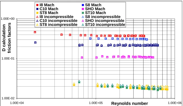
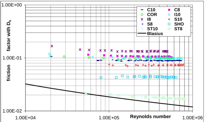
A set of various spiral samples has been tested in these two facilities, providing a double database of friction factors in N2 and H2O flows. Results are to be compared as a function of the Reynolds number, and taking into account the Mach number during experiments (in the compressible N2 case).
Section 2.2 is dedicated to pressure drop measurements in N2 using the OTHELLO facility. Starting from the report by Nicollet [Nic03], the specific contributions added are the influence of Mach number in the compressible nitrogen, the choice of a hydraulic diameter, the comparison of results using external, internal or hydraulic diameter and modelling the role of geometric parameters.
The experimental campaign and samples instrumentation is first detailed. Friction factor calculation methodology is then explained, taking into account properly the Mach number of the fluid. Finally, results and precision are given.
2.2.1 Experimental campaign
The OTHELLO test facility was built at CEA/Cadarache to investigate the hydraulic behaviour of dual channel CICC samples. It is dedicated to hydraulic resistance measurements using nitrogen at ambient temperature. More information about this facility is developed in appendix A1.
Samples
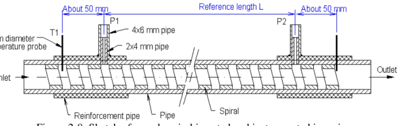
The OTHELLO facility allows the high pressure testing of spirals in an open loop with disposable nitrogen. Spirals samples over 4 m long were mounted in soft pressurised tubing, and eventually mounted again in stainless steel pipes to check results and for more tests in the HECOL facility. For stainless steel tubing, spirals were inserted into pipe with the method called “Overtwist”. It consisted in twisting the spiral over an internal rod to reduce slightly its outer diameter, then relaxing it inside a pipe chosen for its internal diameter. Local brazing of the spiral through holes every half meter tied spiral and tube to avoid twist pitch variation and vibration.
![Figure 2-1: Theoretical and experimental pressure drop as a function of mass flow rate on the TFMC conductors tested in TOSKA (FZK) [Nic02]](https://thumb-eu.123doks.com/thumbv2/123doknet/12894125.370868/30.892.217.683.425.736/figure-theoretical-experimental-pressure-function-conductors-tested-toska.webp)