HAL Id: hal-02988638
https://hal.archives-ouvertes.fr/hal-02988638
Submitted on 25 Nov 2020HAL is a multi-disciplinary open access archive for the deposit and dissemination of sci-entific research documents, whether they are pub-lished or not. The documents may come from teaching and research institutions in France or abroad, or from public or private research centers.
L’archive ouverte pluridisciplinaire HAL, est destinée au dépôt et à la diffusion de documents scientifiques de niveau recherche, publiés ou non, émanant des établissements d’enseignement et de recherche français ou étrangers, des laboratoires publics ou privés.
micrObs – A customizable time-lapse camera for
ecological studies
Alexander Winterl, Sebastian Richter, Aymeric Houstin, Anna Nesterova,
Francesco Bonadonna, Werner Schneider, Ben Fabry, Céline Le Bohec, Daniel
Zitterbart
To cite this version:
Alexander Winterl, Sebastian Richter, Aymeric Houstin, Anna Nesterova, Francesco Bonadonna, et al.. micrObs – A customizable time-lapse camera for ecological studies. HardwareX, Elsevier, 2020, 8, pp.e00134. �10.1016/j.ohx.2020.e00134�. �hal-02988638�
HardwareX article template
Title: micrObs ‐ a customizable time‐lapse camera for ecological studies
Authors: Alexander Winterl1,2, Sebastian Richter1,2, Aymeric Houstin3,4, Anna P. Nesterova4,5,
Francesco Bonadonna6, Werner Schneider1, Ben Fabry1, Céline Le Bohec3,4, Daniel P. Zitterbart1,2
Affiliations: 1Department of Physics, Friedrich‐Alexander University of Erlangen‐Nürnberg, Erlangen, Germany 2Applied Ocean Physics and Engineering, Woods Hole Oceanographic Institution, Woods Hole, USA 3Centre Scientifique de Monaco, Département de Biologie Polaire, Monaco, Principality of Monaco 4Université de Strasbourg, CNRS, IPHC, UMR 7178, Strasbourg, France 5INRA ‐ CNRS ‐ Université de Tours ‐ IFCE, UMR 7247, 37380 Nouzilly, France 6CEFE, Univ Montpellier, CNRS, Univ Paul Valéry Montpellier 3, EPHE, IRD, Montpellier, France Contact email: [email protected] Abstract: Camera traps for motion‐triggered or continuous time‐lapse recordings are readily available on the market. For demanding applications in ecology and environmental sciences, however, commercial systems often lack flexibility to freely adjust recording time intervals, suffer from mechanical component wear, and can be difficult to combine with auxiliary sensors such as GPS, weather stations, or light sensors. We present a robust time‐lapse camera system that has been operating continuously since 2013 under the harsh climatic conditions of the Antarctic and Sub‐Antarctic regions. Thus far, we have recorded over one million images with individual cameras. The system consumes 122 mW of power in standby mode and captures up to 200,000 high‐resolution (16 MPix) images without maintenance such as battery or image memory replacement. It offers time‐lapse intervals between 2 s and 1 day, low‐light or night‐time power saving, and data logging capabilities for additional inputs such as GPS and weather data.
2 Graphical Abstract:
Keywords: automated camera system, image processing, remote sensing, ecology, collective behavior, wildlife monitoring Specifications table Hardware name micrObs Subject area
● Biological Science
● Environmental Sciences
Hardware type● Imaging tools
● Field measurements and sensors
Open Source License GPL CC‐BY 4.0Cost of Hardware 440 € (minimal system: camera, control box, housing), 957 € full system (camera, control box, housing, battery, battery case, solar panel, charger, tripod, mounting) Source File Repository 10.5281/zenodo.3756718 1. Hardware in context Automated imaging is widely used in ecological studies, e.g. for monitoring the occupancy of breeding sites in penguin colonies (Jones et al., 2018), collective movement of chickens (Dawkins et al., 2012),
flocks of birds (Ballerini et al., 2008), mating of mosquitoes (Butail et al., 2012), hunting strategies in bats (Hristov et al., 2008), grouping of midges (Attanasi et al., 2014), or the huddling of emperor penguins (Aptenodytes forsteri) (Richter et al., 2018b). The recording hardware used in such studies can vary from camera traps (Jones et al., 2018), semi‐automatic camera systems (Lynch et al., 2015), DSLR cameras with custom trigger electronics (Newbery and Southwell, 2009), to autonomous multi‐ camera arrays (Richter et al., 2018a). Also, requirements regarding frame rate and image resolution can vary greatly. For studies that focus on slowly changing parameters such as population size and breeding site occupancy, long image intervals (1 image per hour to 1 image per day) are sufficient, and accordingly the total number of acquired images remains small, with typically less than a few thousand images per camera and season. By contrast, behavioral studies require higher frame rates to identify individual motion and interaction between individuals, ranging from 1 frame per minute for studying breeding penguins (Jones et al., 2018; Zitterbart et al., 2011) to video frame rates (Butail et al., 2012) or even high‐speed cameras (Attanasi et al., 2014) for studying collective order in swarms of midges. Unfortunately, frame rates between one frame per second to one frame per minute are often not available in commercial camera traps and time‐lapse cameras, or if they are, longer recording periods of several days or weeks cannot be achieved for various reasons such as mechanical camera failure after 100,000 images (Improve Photography, 2020). This lack of long‐term recording hardware is especially critical for studies in which the behavior of a species needs to be observed over a significant part of its annual cycle, for example emperor penguins that remain continuously at the breeding colony for over 130 days (Richter et al., 2018b). Another disadvantage especially of low‐cost commercial systems is their poor image quality as regards image resolution and noise performance in low‐light conditions.
Here, we present a low‐cost, high‐resolution, sturdy and water‐resistant time‐lapse camera system (micr0bs) (Fig. 1) based on customized consumer components. The camera system was designed to record time‐lapse images continuously and autonomously at frame rates between 0.5 frames per second and 1 frame per day with an image storage capacity of 1024 GByte (~200,000 jpeg‐compressed 16 MPix images). Furthermore, the system was optimized for minimum power consumption and offers auxiliary data logging capabilities, for example to record local weather conditions. micr0bs systems have been deployed since 2013 under the harsh climatic conditions of Antarctica and the Sub‐ Antarctic Islands, with some of the cameras having recorded more than 1 million images (Table 6). 2. Hardware description The camera system was designed to handle a large range of time‐lapse applications. This foremost includes a wide range of image recording rates (2s ‐ 24h), low power consumption and large image storage capacity to maximize runtime. The camera system offers auxiliary data logging capabilities, for example to record local weather conditions. We foresee the main applications to fall into one of the following categories:
● Continuous observation of individual behavior, e.g. tracking predation events in a seabird colony at high temporal resolution of 1 image every 5 seconds for 12 days
4 ● Investigation of collective behavior events, e.g. observing penguin huddle formation at
intermediate temporal resolution of 1 image every minute for 20 weeks
● Long‐term monitoring of landscapes, aggregations, or population sizes of animals, e.g. observing nesting seabirds at low temporal resolution of 1 image per hour for 4 years
2.1 Camera choice
Existing solutions for automated image capture can be divided into four categories: camera traps, action cameras, consumer digital single lens reflex (DSLR) cameras, and computer‐assisted image acquisition system based on industrial cameras. In Table 1, we compare representative examples of such systems to our approach (micrObs). Camera traps such as the Bushnell impulse trail (Bushnell Outdoor Products, 2020) are designed for long deployment times, low energy uptake, and harsh environmental conditions. Typically, they are used to record a picture/video on demand after being triggered by motion or a thermal signal from a passing animal. These systems often support time‐lapse imaging but cannot record more than several thousand images during a deployment period due to their limited memory capacity and battery lifespan. Furthermore, their image quality is limited by low‐resolution lenses, small apertures, lack of automatic aperture and focus settings as well as small sensor sizes and low image resolution. Action cameras such as the goPro Hero 8 (goPro, 2020) are primarily used for frame rates between 30 fps and 120 fps, but they also support time‐lapse modes (goPro, 2019). Similar to camera traps, they are limited by battery capacity and image storage capacity. There are solutions bypassing this issue with additional hardware (BlinkX, 2020; Greene et al., 2020). However, further drawbacks of these cameras are their wide‐angle lenses and small image sensors that perform poorly under low‐light conditions. The use of consumer DSLR cameras for time‐lapse recordings is widespread in construction progress documentation (Harbortronics Inc., 2020). In addition, there is a noncommercial system already in use to study penguin population dynamics (Newbery and Southwell, 2009; Southwell et al., 2014). These systems are closest to our requirement in image quality and range of time‐lapse intervals. However, DSLR cameras suffer from mechanical wear of the mirror and shutter, which are moved during each image capture. This limits the lifetime of a DSLR camera to about 50,000 to 100,000 images. Furthermore, in extreme cold, DSLR fail mechanically: shutter and mirror move slowly, become stuck or damaged (Zitterbart et al., 2011). The DSLR in both systems can be replaced with a mirrorless interchangeable‐lens camera with an electronic shutter, however, the relatively high cost of the commercial system and the absence of open soft‐ and hardware documentation for the noncommercial system remain an issue.
Custom image acquisition systems based on industrial cameras and controllers (Richter et al., 2018a) are expensive, bulky, have a high energy consumption, and require the user to develop customized algorithms for the automatic control of aperture, gain, exposure time, and focus distance. Software and hardware for compression and management of the recorded images further increase the complexity.
Our “micrObs” imaging system is based on the Panasonic Lumix DMC G5, a commercially available digital mirrorless camera that offers an electronic shutter, external trigger, optional external power supply, and high‐quality interchangeable fixed or adjustable focal length lenses with large aperture. We use a wide‐to‐medium angle telephoto lens (Panasonic H‐FS014042E) with a focal length of 14‐42 mm (28‐48 mm in 35 mm equivalent). We use the manual focus option to set the focus point (usually to infinity). This prevents blurred images due to an unsuccessful autofocus search in scenes with poor light or poor visibility, and further reduces the number of moving parts. Table 1: Comparison of four time‐lapse recording systems for frame rates between 1/s and 1/day. *Images per battery charge are calculated based on a 3Ah 12V battery for comparability. References: 1(Bushnell Outdoor Products, 2020), 2(Harbortronics Inc., 2020), 3(Newbery and
Southwell, 2009), 4(BlinkX, 2020), 5(goPro, 2020), 6(Canon, 2016), 7(Canon, 2018), 8(Bushnell
Outdoor Products, 2017) 9(Panasonic Corporation, 2012).
System Type Camera Trap Action Camera DSLR camera Mirrorless camera Name Bushnell Impulse Trail GoPro HERO8 + CamDo BlinkX Cyclapse Newbery & Southwell 2009 micrObs Price 265 €1 692 € 4,5 3372 € 2 N. A. (~1000 €) 3 957 € Electrical Shutter
Yes 8 Yes 5 No No 3 Yes 9
Mirror No 8 No 5 Yes 7 Yes 3 No 9
Camera integrated 8 GoPro Hero 8 5 Canon EOS‐ 1500D / Rebel T7 2 Canon EOS‐ 1300D / Rebel T6 3,6 Panasonic Lumix G5 Other Cameras Possible No 8 GoPro Hero 5 to 8 4
Yes 2 Yes 3 Yes
Image Resolution
8 MPix 8 8 MPix 5 24 MPix 7 6.3 MPix 6 15.9 MPix 9
FOV (typical) 38° 8 68°‐122° 5 23‐63° 7 23‐63° 3 23°‐63°
Other Lenses Possible
No 8 No 5 Yes 7 Yes 6 Yes
Images per Battery Charge*
6 Image Interval 1 min to 1 h 8 0.5 s to 1 h 4 1 s to 24 h 2 1 h to 24 h 3 2 s to 24 h
Max Image Storage 32 GB (SDHC) 8 1024 GB (SDXC) 5 1024 GB (SDXC) 7 1024 GB (SDXC) 6 1024 GB (SDXC) 9 Reference Timing GSM 8 wifi & NTP server 4 RTC 2 RTC 3 GPS Power per Image 10 mWh 8 40 mWh 4 38.4 mWh 2 6.9 mWh 3 5.64 mWh Standby Power Usage 0.96 mW 8 10 mW 4 100 mW 2 0.96 mW 3 122 mW Regenerative Power No Solar (additional cost)
Solar 2 Solar 3 Solar
Open Source No No No No Yes
Open Hardware
No No No No Yes
Hardware User Interface
Yes 8 No No No Yes
Light Sensor Yes 8 No Yes 2 No Yes
GPS Yes 8 Yes 5 No No Yes
Automatic Weather Station
No No No No Yes (optional)
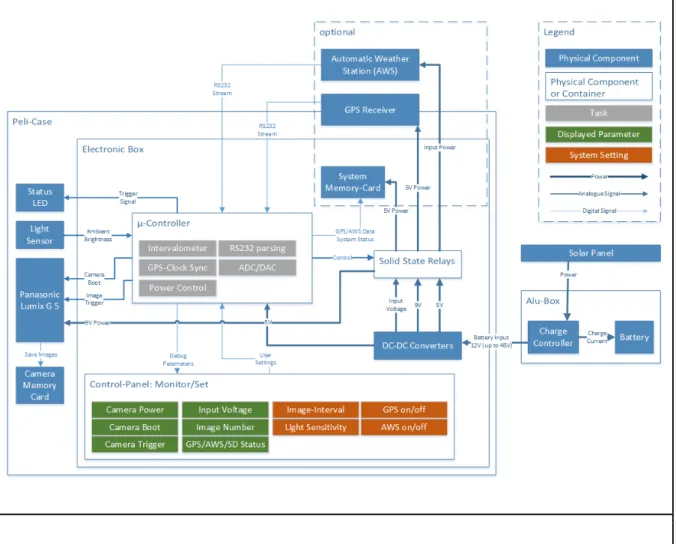
Fig. 1: micrObs recording system in the field. (A) The camera housing contains the control box and camera. (B) System deployed in the field at Pointe Géologie archipelago, Adélie Land, Antarctica (66°42′01″S 139°49′41″E, May 2019). The camera housing is mounted on a tripod with a pan/tilt ball mount. The system is powered by a 12 V car battery with a solar panel and charge regulator. (C) Image recorded with micrObs. (D) Enlarged detail: Individual animals are clearly distinguishable. 2.2 Camera control The recording system is controlled by an Arduino Nano microcontroller (Arduino, 2020) mounted onto a custom printed circuit board. The microcontroller monitors battery voltage and ambient light conditions. It powers and boots the camera, and triggers the image acquisition (see Fig. 2 and Fig. 3). The microcontroller also logs the data from a GPS module, a weather station (AWS), or any other RS232‐capable device, to an interchangeable memory card (microSD). We choose the Arduino over alternative controllers with lower power requirements because of the large user community providing existing hardware and software solutions such as the SD card board.
8 We control the camera’s boot and shut down commands by replacing the camera's manual power switch with an electronic switch. This is necessary to ensure a proper shut‐down sequence, as simply disconnecting the external power supply leads to an erroneous numbering of the recorded images. A major limitation of a consumer camera is the inaccuracy of their image timestamps. Even if the camera’s clock is set properly, it will drift noticeable during long‐term deployments. Therefore, in addition to the image timestamp provided by the camera, we log the microcontroller time of each image trigger event in a file. To prevent time drift, we synchronize the microcontroller’s clock once per hour (configurable) to UTC time provided by the GPS module. To reference the camera‐provided image timestamp to the microcontroller‐provided trigger time, we acquire two images with no (minimal) time delay each time the microprocessor's clock is synchronized. For most applications, ambient light conditions will occasionally be insufficient for image acquisition, e.g. due to day‐night cycles or weather changes. To save energy and storage space, micrObs measures the ambient light intensity with a photoresistor and interrupts recording if it falls below a user‐defined threshold. To simplify the camera setup procedure under poor weather conditions, the user can adjust the frame rate and illumination threshold via the front panel of the control box (see Fig. 1A). A display informs the user of image interval, current ambient illumination, illumination threshold, connected RS232 devices such as a weather station, battery voltage, availability and functionality of GPS, and memory card.
The control box can in principle control any camera that offers external power supply and shutter release. The voltage levels of the camera power supply and the shutter release are adapted to our camera model but can be changed by adjusting resistors R6 and R7 and the voltage converter TSR‐ 2490 (see design file MainPCB.sch).
Fig. 2: Schematic of the camera control setup.
Fig. 3: Camera control software block diagram. 2.3 Other components The housing of the recording system needs to withstand severe weather conditions like heavy rain, drifting snow or ice buildup as well long‐term UV exposure. The housing is chosen as small as possible to reduce wind‐induced vibrations. It holds the camera, the control unit, and the GPS receiver (NL‐ 604P, Navilock). We chose a plastic housing with rubber sealing (Protector 1150, Peli). Cables to the battery box and external weather station are connected to the controller via waterproof cable‐glands. The cutout for the camera's viewport through the enclosure is covered with a standard 52 mm UV filter used for photography and sealed with a custom‐made rubber gasket that is compressed to the enclosure by a bracket. The housing is water resistant (comparable to IP66 rating) but not submersible. It is attached to a tripod via a custom pan‐tilt mount that is easily operable and fits most tripods. The tripod (berlan BST285A) used in our application is a standard surveillance equipment tripod and was chosen based on its low cost and light weight (aluminum construction). If a rechargeable battery with solar panels is to be used, the solar panel is mounted on a separate aluminum box (Zarges) that also houses the charge controller and battery. For transportation, the camera case is designed to fit into the battery box as well. Depending on battery weight and size, transport and setup of the system is possible with one or two persons.
For the battery, we chose a deep cycle, non spillable, lead gel battery (Lifeline GPL‐U1T), which, for our application, was the best compromise between weight (10.9kg), price (170€) and capacity (33Ah, 12V). A 30 W solar module (Offgridtec 3‐01‐001530) that fits on the aluminum box charges the battery
12 3. Design files
Design files summary
Design file name File type Open source license Location of the file MainPCB.sch EAGLE Circuit file CC‐BY 4.0 10.5281/zenodo.3756
718
MainPCB.brd EAGLE Board file CC‐BY 4.0 10.5281/zenodo.3756
718
FrontPCB.sch EAGLE Circuit file CC‐BY 4.0 10.5281/zenodo.3756 718
FrontPCB.brid EAGLE Board file CC‐BY 4.0 10.5281/zenodo.3756 718
Enclosure.svg vector graphic CC‐BY 4.0 10.5281/zenodo.3756
718
WindowMount.svg vector graphic CC‐BY 4.0 10.5281/zenodo.3756 718
PanTiltMount.stp step file with CAD drawing CC‐BY 4.0 10.5281/zenodo.3756 718 Table 2: Hardware design files. MainPCB.sch: Documentation file containing the circuit schematic for the custom electronic board. MainPCB.brd: The print circuit board layout file of the main board of the control unit. Most manufacturers accept this filetype, otherwise it can be opened with the free version of AutoCAD Eagle, to derive other file types (e.g. Gerber files). FrontPCB.sch: Documentation file containing the circuit schematic for the breakout board of the front panel. FrontPCB.brd: The print circuit board layout file. See MainPCb.sch. Most manufacturers accept this filetype, otherwise it can be opened with the free version of AutoCAD Eagle, to derive other file types (e.g. Gerber files).
Enclosure.svg: Vector graphics file containing the plans for the control box. The control box can be laser cut from 3 mm acrylic glass using this file. It contains engraving paths as well as cutting paths. It can be opened and manipulated with the open source program Inkscape or similar software.
WindowMount.svg: Vector graphics file containing the plans for the camera window mount. The window mount can be laser cut from 3 mm acrylic glass and 1 mm chlorine free rubber using this file. It can be opened and manipulated with the free program Inkscape or similar software.
PanTiltMount.stp: A step file containing the drawing of the pan and tilt mount. It can be opened with many CAD programs like SolidEdge, which we used for creating the drawing.
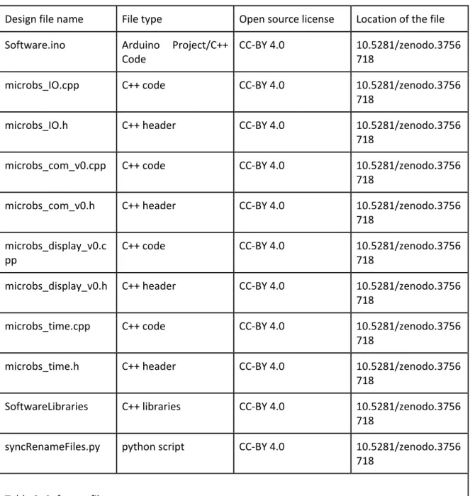
Design file name File type Open source license Location of the file Software.ino Arduino Project/C++
Code
CC‐BY 4.0 10.5281/zenodo.3756 718
microbs_IO.cpp C++ code CC‐BY 4.0 10.5281/zenodo.3756
718
microbs_IO.h C++ header CC‐BY 4.0 10.5281/zenodo.3756
718
microbs_com_v0.cpp C++ code CC‐BY 4.0 10.5281/zenodo.3756
718
microbs_com_v0.h C++ header CC‐BY 4.0 10.5281/zenodo.3756
718 microbs_display_v0.c
pp
C++ code CC‐BY 4.0 10.5281/zenodo.3756
718
microbs_display_v0.h C++ header CC‐BY 4.0 10.5281/zenodo.3756 718
microbs_time.cpp C++ code CC‐BY 4.0 10.5281/zenodo.3756
718
microbs_time.h C++ header CC‐BY 4.0 10.5281/zenodo.3756
718
SoftwareLibraries C++ libraries CC‐BY 4.0 10.5281/zenodo.3756 718
syncRenameFiles.py python script CC‐BY 4.0 10.5281/zenodo.3756 718
Table 3: Software files.
14 microbs_IO.cpp: Get and set micrObs inputs and outputs. Handling of analog averaging and multiplexer. microbs_IO.h: Settings and definitions of inputs and outputs. microbs_com_v0.cpp: Communication with GPS, weather station and control box memory card. microbs_com_v0.h: Settings and definitions of communication modules. microbs_display_v0.cpp: Front panel routines for display and LEDs. Debug strings for display. Set/get methods for system settings (interval, light sensitivity, GPS/weather station activity). microbs_displa_v0.h: Definitions for front panel routines. microbs_time.cpp: Timing routines: interval timer, syncing with GPS, time display, reset functions. microbs_time.h: Definitions of timing routines. Software Libraries: Contains Open Source Libraries like Adafruit_LED_Backpack, Low‐Power, SdFat. syncRenameFiles.py: This file contains a self‐explanatory (help function) python (version>3.4) script used to synchronize the recorded images from the camera memory card with the timestamps and meta information from the control box’ memory card. 4. Bill of materials Table 4: Short bill of materials.
Designator Component Number
Cost per unit ‐ currency Total cost ‐ currency Source of Material Materia l type Camera Panasonic Lumix G5 1 99 € 99 € mpb.com other Lens Panasonic Lumix G Vario 14‐42mm Vario f/3.5‐5.8 ASPH Mega OIS 1 64 € 64 € mpb.com other
housing Pelicase 1150 1 42 € 42 € pelishop.com other
Battery Lifeline GPL‐ U1T 1 170 € 170 € akkuangebote.de other Charge Regulator Steca Solsum 0606 1 20.99 € 20.99 € conrad.de other
Tripod berlan BST285A 1 40 € 40 € Bergland (ebay) other Photovoltaik Module Offgridtec 30W 12V 1 44.90 € 44.90 € amazon.de other GPS Navilock NL‐ 604P 1 65 € 65 € amazon.com other Transport‐ Box
Zarges40877 1 140 € 140 € zarges.com other
DC‐Adapter Panasonic DWM‐DCCG8 1 10 € 10 € amazon.com other SD‐Card Reader SPIReader AZDelivery 1 2 € 2 € amazon.com other MicroControl ler
ArduinoNano 1 23 € 23 € amazon.com other
W4* Walimex UV Filter 52mm 1 5 € 5 € amazon.com other C1, C2, C3, C4, C5, C6, C7, C8, W1, W2* Acrylic glass 3mm x 60 cm x 30 cm 1 6.58 € 6.58 € Plattenzuschnitt 24.de acrylic W3 chlorine free rubber 1mm x 60mm x 60mm 1 18 € 18 € amazon.com rubber
MainPCB MainPCB 1 30 € 30 € multiCB other
Frontpanel‐ PCB Frontpanel‐ PCB 1 10 € 10 € multiCB other Control Box Electronic
components ‐ ‐ 58.09 € conrad/mouser other
Control Box/Housing
Mechanical
components ‐ ‐ 14.34 € conrad other
Mount
Mount
16 Transport Box
Components
Mechanical and electrical
components ‐ ‐ 52.93 € hardware store other
Sum 956.56 € * Part numbers such as W4, C2 etc refer to the parts shown in Figure 4 in Supplementary File 2. We included a detailed bill of materials with the other design files (10.5281/zenodo.3756718) and in Supplementary File 1. The control box housing can be ordered from a laser cutting service or manufactured at a local fab lab using the provided drawings. The control box housing (parts C1‐C8, see Fig. 4 in Supplementary File 2) is made out of 3 mm black cast acrylic glass (PMMA). The window parts W1 and W2 are made out of 3 mm acrylic glass, and W3 is made out of 1 mm thick chlorine free rubber.
The electronic parts and most of the smaller mechanical parts can be purchased through online retailers such as conrad.de or mouser.com.
Aluminum for larger mechanical components (e.g. for the tripod mount) can be purchased from a local hardware store. We manufactured the tripod mount at our institute's mechanical workshop.
The hardware costs for a minimum configuration of the system consisting of the enclosure box, camera, control electronics and GPS are 440 €. This does not include the costs for an external power supply (289 €) and tripod mounting (228 €). All prices include German VAT of 19 %.
5. Building Instructions
We provide a detailed step‐by‐step building instruction in Supplementary File 2. The instruction contains descriptions and pictures of the assembly of the control box, the customization of the camera, the construction of the front panel, a drilling plan for the outer housing, and a building instruction for the window mount. It does not contain instructions on how to cut acrylic glass, how to manufacture the pan and tilt mount, how to make a PCB from the design files or how to solder components. If an in‐house workshop for these tasks is not available, they can be outsourced (e.g. Online PCB Services, Laser Cutting Services). In the following, we give a brief summary of the instructions:
Pry open the camera body and replace the hardware switch by two cables connected to the former hardware switch pads. Drill a hole in the camera body to feed‐through the cables. Re‐assemble the camera body. Replace the camera battery with the DC‐adapter. (See chapter 2 in Supplementary File 2.)
Fabricate the acrylic glass parts (C1‐C8) shown in Enclosure.svg and (W1, W2 x 2) shown in WindowMount.svg from 3 mm cast acrylic glass (PMMA) using a laser cutter. Fabricate the rubber sealing W3 shown in WindowMount.svg. Glue the enclosure from parts C2‐C7 using an adhesive for
acrylic glass (Acryfix, Evonic). Drill the M2 threads in the sides and the 6 mm countersunk holes in the top and bottom piece of the control box housing. (See chapter 4.1 in Supplementary File 2.) Produce the Main PCB and Frontpanel PCB (printed circuit board) from the design files MainPCB.brd and FrontPCB.brd. Solder the electronic components (D1, IC1, Q1‐Q9, R1‐R23, REED, TSR‐1‐2450, TSR‐ 1‐2490, U1, X1, X2, Ca1, Ca2) to the main board. (See chapter 3 in Supplementary File 2.) Mount the main board into the control box housing. Assemble the connectors for the weather station and GPS, mount them to the control box, and connect them to the main PCB. Assemble the front panel from the control box housing top acrylic glass piece (C7, C8 x2), the front panel circuit board, buttons (B1, B2, B3) , hexadecimal encoder (H), potentiometer (M), knobs (K1,K2), display (D) and LEDs (L1‐ L7). Assemble the connector ribbon cable (MM) with the connectors (P4, P5). Connect front panel and main PCB. Put the SD card reader in the socket on the main board. (See chapter 4.2 in Supplementary File 2.) Flash the Arduino with the C++ software (software.ino) using the Arduino IDE software and a mini USB connector. Put the Arduino in the socket on the main board. Close the control box housing. Assemble the trigger cable from the core of the audio jack (P6) with two 0.5 mm² wires. Assemble the light sensor from the photoresistor (R0), the plastic mantle of the audio jack (P6) and two 0.5 mm² wires. Drill holes for the camera mount, window, light sensor, GPS, and power cable gland (T1, T2) in the housing. Assemble the window mount from the laser cut window mount parts (W1‐W4) and secure it to the housing. Mount the camera and GPS inside the housing. Assemble the GPS connector plug. Connect the camera to the control box via the trigger cable, customized camera power switch cable, and dc adapter cable. Double check (!) the polarity of the camera power connection. (See chapter 5 in Supplementary File 2.) Connect the light sensor and GPS. Put a SD card in the camera and a micro SD card in the control box. Push the debug button and connect the control box to power. The system should boot, start up the camera, and display the system parameters. (See chapter 6 in Supplementary File 2) We use the transport box as a housing for the battery and charge regulator and as a support for the solar panel. Detailed instruction for the customization of the transport box, wiring, mounting the solar panel and mechanically securing the battery are given in chapter 7 in Supplementary File 2. 6. Operation instructions We include a user’s manual in Supplementary File 3, which explains the setup in the field, front panel setup options and synchronization software. In the following, we describe the typical use case. The battery box with the camera and tripod can be easily carried by two people. Remove the camera housing and solar panels from the transport box and connect cables to the outer sockets. For most applications, the camera should be positioned as high as possible above the imaged area to achieve a high observation elevation angle. This is usually associated with a high wind load. We reduce wind‐ induced shaking and tilting by attaching a heavy weight to the camera mount/tripod. For example, a
18 tarpaulin or net can be attached to the tripod, which is then loaded with stones or other heavy material available on site. Alternatively, tent pegs can be used to secure the tripod. The camera mount allows for +/‐ 15 degrees of tilt and 360° of panning. For better access while setting pan, tilt, and recording parameters, the camera housing can be opened and closed without moving or touching the camera. To adjust recording settings, first switch to setup mode by pressing the red setup button (red LED will turn on). The button will click and stay in the latched position. While in setup mode, no images are acquired. To resume time‐lapse operation, click the setup button again (red LED will turn off). While in setup mode, the control box’ display shows the current parameters of the system: Image interval, ambient light threshold, GPS activity, weather station activity, µSD card presence and power supply voltage. To change those parameters, set the image interval, the GPS and weather station usage and the light sensor threshold using their respective control/button. The settings will be saved when the setup mode is exited. After exiting the setup mode, recording will start immediately, and the control box will display the cumulative number of recorded images after each trigger event. The “Power” LED indicates the supply of the camera with power, the “Boot” LED indicates if the camera is switched on, the “Trigger” LED lights up shortly when an image is triggered. If micrObs is disconnected from power intentionally or unintentionally (e.g. to exchange the battery), it is not necessary to reset any parameters. The control box saves the last setup on its µSD card and continues recording when re‐powered. Likewise, the system resumes recording after a power loss, e.g. when connected to a variable power source like a photovoltaic panel. Control box memory card and camera memory card should always be exchanged together, to keep the timestamp and meta information synchronous with the recorded images. We provide a software tool for reordering and renaming of image files based on the timestamps from the control box’ µSD card. 7. Validation and characterization micrObs supports 9 different time lapse intervals between 2 s (fastest) and 1 h. The use of the light sensor, GPS, and a second RS232 device can be enabled or disabled. If needed, these default time lapse intervals can be changed in the Software.ino file, but 2 s is the fastest interval due to camera limitations. The performance characteristics and limitations with our configuration (12 V 30 Ah battery (3,600 Wh), 1 TByte memory card for the images) are: ● Capture more than 200,000 images (this requires recharging of the battery) ● Capture up to 64,000 images on a single battery charge ● Record for up to of 98 days on a single battery charge ● Relative deviation of the timer interval from the target value is less than 0.1 %
7.1 Timing and power drain
We minimize the energy consumption of our recording system by optimizing the component uptime, keeping components only powered when necessary. Therefore, we switch‐off the camera between two images if the image interval is larger than 10 s or when there is not sufficient ambient light (e.g. night, storm). Power consumption is 152.4 mW during the power‐down phases (Fig. 4B). A single charge of a 3,600 Wh (12V 30 Ah) battery lasts for up to 64,000 images recorded at the highest frame rate, or up 98 days when images are recorded at the lowest frame rate (if no additional RS232 device other than the GPS device is powered, see Table 5). The light sensor (to automatically turn‐off recording during low‐light conditions), GPS, and a second RS232 device can be switched on or off. The power consumption during the power‐down phases can be further lowered to 122 mW by removing the microcontroller’s status LEDs and removing the built‐in power converter of the Arduino‐controller, which are not necessary for operation. If solar power (with a small buffer battery) is sufficient to power micr0bs continuously (e.g. 3W average consumption, 30W solar panel), the system’s maintenance interval is only limited by the camera’s image memory card size. With a 1TB memory card, the camera can capture more than 200,000 16 MPix 98% quality jpeg images. Table 5: Runtime and image memory usage for different recording intervals. Image interval # Images Runtime (30Ah 12V battery) Camera memory usage 2s 64k 35h 319 GB 5s 64k 88h 319 GB 10s 64k 7 days 319 GB 30s 56k 19 days 277 GB 1min 46k 32 days 232 GB 5min 20k 69 days 100 GB 10min 12k 81 days 59 GB 30min 4421 92 days 22 GB 1h 2284 95 days 11 GB 6h 391 97 days 2 GB 24h 98 98 days 0.5 GB
20 Fig. 4: Validation of time interval precision and power drain. (A) Deviation of the image interval relative to the target interval for different settings. Each point corresponds to an independent measurement, colors indicate the performance of different microcontrollers. The boxplot (median, 25 and 75 percentiles) shows the data pooled over all measurements from all microcontrollers for the same setting. Whiskers show the 1.5 interquartile range. (B) Power drain during image capture without GPS or other RS232 device. The pink area corresponds to the energy consumed for the capture of one image (20.3 Ws). The blue shaded area indicates the power consumption in standby mode (152 mW). Vertical lines indicate the phases of image capture initiated by the microcontroller. micrObs supports 9 different image intervals between 2s and 1h. Each image is provided with a GPS time stamp. We verified the image interval by measuring the timing accuracy of the Arduino’s internal clock. In particular, we measured four different micrObs devices at four settings for the sleep timing (the time the system spends in deep sleep without interruption) and image intervals (the actual time between images): 0.5 s sleep at 1 h image interval, 0.5 s sleep at 10 s interval, 1 s sleep at 30 s interval, and 0.5 s sleep at 30 s interval. We then compared the Arduino’s internal timestamp to a network
time protocol‐synchronized pc timestamp and found that the relative deviation from the target interval for each of the devices was below 0.1% (Fig. 4A).
7.2 Field test
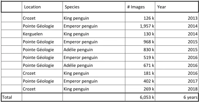
With five separate micrObs system, we recorded time‐lapse images of penguin colonies of three species (Emperor penguins (Aptenodytes forsteri), Adélie penguins (Pygoscelis adeliae), and King penguins (A. patagonicus)) at three different locations: Pointe Géologie archipelago (Adélie Land, Antarctica), Kerguelen (Ratmanoff Cape), and Crozet (Baie du Marin on the Possession Island). During 6 years of operation, we recorded over 6 million images (see Table 6).
Table 6: Operation statistics since 2013.
Location Species # Images Year
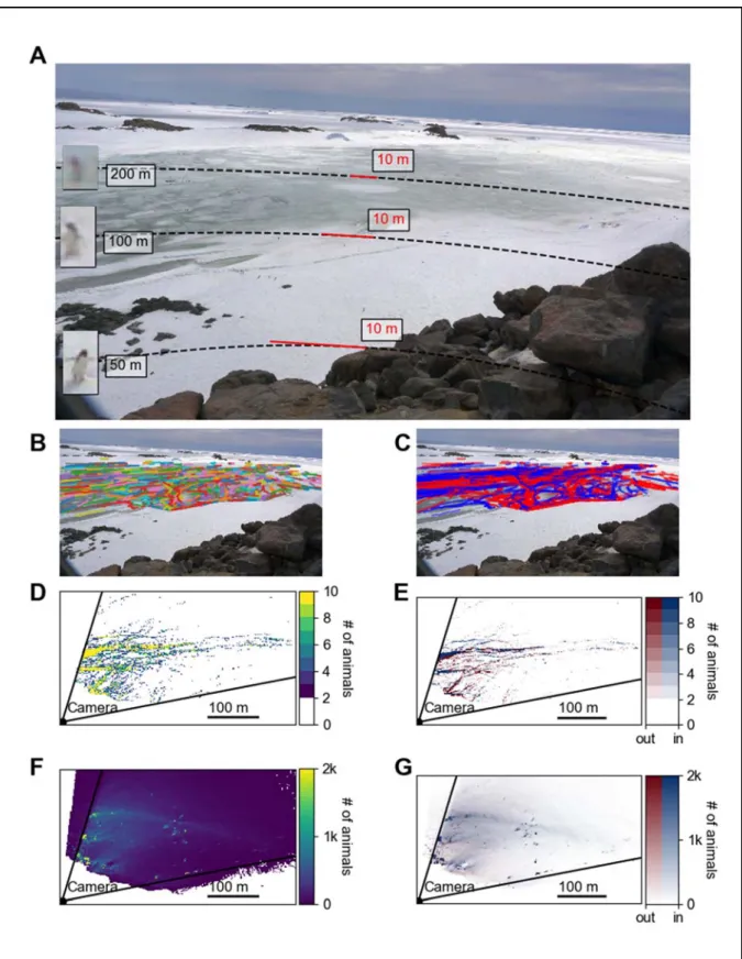
Crozet King penguin 126 k 2013 Pointe Géologie Emperor penguin 1,957 k 2014 Kerguelen King penguin 130 k 2014 Pointe Géologie Emperor penguin 968 k 2015 Pointe Géologie Adélie penguin 830 k 2015 Pointe Géologie Emperor penguin 519 k 2016 Pointe Géologie Adélie penguin 671 k 2016 Crozet King penguin 181 k 2016 Pointe Géologie Emperor penguin 402 k 2017 Crozet King penguin 269 k 2018 Total 6,053 k 6 years 7.2.1 Path finding in foraging Adélie penguins During the austral summer, approximately 47,000 Adélie penguin pairs (Pygoscelis adeliae) breed at Pointe Géologie close to the French Antarctic research station of Dumont d’Urville (Adélie Land, Antarctica)(Barbraud et al., 2020). During breeding, adult penguins alternate between breeding and foraging, forming a continuous stream of thousands of penguins arriving and leaving their colony. Therefore, we persistently encounter trafficking individuals between the open sea and the breeding sites. We continuously observed an area of high traffic over 21 days. To achieve reliable tracking of animals (which are indistinguishable from each other), the distance between two individuals must not be greater than the distance one individual covers between two images. Therefore, the image interval of 2 seconds was selected to track the penguins, yielding 398,149 images in total. We applied an object detection and tracking algorithm to the image series, which generated 7,413,146 detections of individuals, and concatenated them to 373,290 penguin tracks. Individual tracks of 1628
22 penguins during a 17 min recording period are shown in Fig. 5A. Penguin tracks separated into penguins arriving and leaving their colony site are shown in Fig. 5B.
We find that penguins use preferential pathways to commute over the sea ice on short time scales (Fig. 5C), creating “penguin roads”. These penguin roads, however, are not stable over time but meander across the sea ice area during the 21 day recording period so that over time a substantial part of the sea ice area was utilized by the Adélie penguins (Fig. 5F). The high‐density areas (yellow) in Fig. 5F represent points along the road where penguins frequently stop and rest, resulting in a high area usage. We also find that animals leaving and returning to the colony prefer separate trails (Fig. 1D) to avoid collisions.
Fig. 5: (A) Image recorded with micrObs. The dashed curves show circles with distances of 50 m, 100 m, and 200 m around the camera. The solid red lines mark a line of 10 m length at the respective distances from the camera. Insets show examples of penguins at the respective distances. (B) and (C) are images recorded with micrObs overlaid with penguin tracks during a 17 min observation period. Each individual track in (B) is marked by a separate color. Colors in (C) indicate the track
24 direction. Red tracks mark individuals leaving the colony to forage at the open sea (out), blue tracks mark individuals returning to the colony (in). (D) and (E) show ortho‐projected maps, with colors indicating the cumulative animal density (number of detected animals per square meter integrated over a 17 min observation period). The solid lines mark the field‐of‐view of the camera. (D) shows the cumulative density of both outgoing and incoming animals, while (E) shows the cumulative density separately for outgoing (red) and incoming (blue) animals. (F) and (G) show the cumulative density over 21 days for outgoing and incoming animals together (F) or separately (G).
7.2.2 Ecological study on emperor penguins
micrObs was previously used in a published study that analyzed the behavioral response of emperor penguins (Aptenodytes Forsteri) to weather changes (Richter et al., 2018b).
While breeding and fasting under the harsh conditions of the Antarctic winter, emperor penguins (Aptenodytes Forsteri) form tight groups to conserve energy (Ancel et al., 1997). This strategy, called huddling, is the key to their reproductive success. From micrObs time lapse recordings at 30 s time intervals, we measured the area covered by the animals to estimate the colony density. We then interpreted this density as an order parameter for studying colony phase transitions (from a dilute phase to a dense huddling phase) as function of an apparent temperature (Richter et al., 2018b). This apparent temperature is computed as a linear combination of four meteorological parameters (ambient temperature, wind speed, relative humidity, solar radiation) and serves as the thermodynamic variable in a phase transition model. The model predicts the colony’s state depending on the environmental conditions. For this study, we analyzed data from 8 days of recordings (2767 images) between 6th of May and 11th of May 2014 at DDU (see Table 4). The system operated in cold
(average temperature –16.8°C) and low illumination conditions (average solar radiation 1878 W/m²). The 20 Ah battery was replaced every 3 days.
8. Acknowledgements
This study was funded by the Deutsche Forschungsgemeinschaft (DFG) grants FA336/5‐1 and ZI1525/3‐1 in the framework of the priority program “Antarctic research with comparative investigations in Arctic ice areas”, by The Penzance Endowed Fund and The Grayce B. Kerr Fund in Support of Assistant Scientists. This study was also supported by the Institut Polaire Francais Paul‐ Emile Victor (IPEV) within the framework of the Programmes 137‐ANTAVIA (data collection at Crozet and Terre Adélie) and 354‐ETHOTAAF (Kerguelen data collection), by the Centre Scientifique de Monaco (CSM) with additional support from the LIA‐647 and RTPI‐NUTRESS (CSM/CNRS‐UNISTRA), and by the Centre National de la Recherche Scientifique (CNRS) through the Programme Zone Atelier de Recherches sur l’Environnement Antarctique et Subantarctique (ZATA). We thank the IPEV logistics team, the overwinterers at Dumont d’Urville, at Crozet Island, and at Kerguelen Islands for their support. We thank Michael Hoffman for building micrObs control units and reviewing our camera customization instruction.
9. Declaration of interest None.
10. Human and animal rights
This study was approved by the French ethics committee (APAFIS#4897‐2015110911016428 and APAFIS#9496‐201707131540776) and the French Polar Environmental Committee of the Terres Australes et Antarctiques Françaises (TAAF project implementation and access permits #2012‐117 & 2012‐126, 2013‐74 & 2013‐82, 2014‐116 & 2014‐132, 2015‐52 & 2015‐105, 2016‐76 & 2016‐82, 2017‐ 92 & 2017‐102, 2018‐116 & 2018‐129, 2019‐107 & 2019‐115) and conducted in accordance with its guidelines. References Ancel, A., Visser, H., Handrich, Y., Masman, D., Le Maho, Y., 1997. Energy saving in huddling penguins [3]. Nature. https://doi.org/10.1038/385304a0
Arduino, 2020. Arduino Nano | Arduino Official Store [WWW Document]. URL https://store.arduino.cc/arduino‐nano?queryID=857316ca1d122d770407ae81236cc5bd (accessed 5.22.20). Attanasi, A., Cavagna, A., Del Castello, L., Giardina, I., Melillo, S., Parisi, L., Pohl, O., Rossaro, B., Shen, E., Silvestri, E., Viale, M., 2014. Collective Behaviour without Collective Order in Wild Swarms of Midges. PLoS Comput. Biol. 10. https://doi.org/10.1371/journal.pcbi.1003697 Ballerini, M., Cabibbo, N., Candelier, R., Cavagna, A., Cisbani, E., Giardina, I., Lecomte, V., Orlandi, A., Parisi, G., Procaccini, A., Viale, M., Zdravkovic, V., 2008. Interaction ruling animal collective behavior depends on topological rather than metric distance: Evidence from a field study. Proc. Natl. Acad. Sci. U. S. A. 105, 1232–1237. https://doi.org/10.1073/pnas.0711437105
Barbraud, C., Delord, K., Bost, C.A., Chaigne, A., Marteau, C., Weimerskirch, H., 2020. Population trends of penguins in the French Southern Territories. Polar Biol. 1, 3. https://doi.org/10.1007/s00300‐020‐02691‐6
BlinkX, 2020. BlinkX User Manual [WWW Document]. URL https://cam‐do.com/pages/blinkx‐user‐ manual (accessed 5.22.20). Bushnell Outdoor Products, 2020. Performance Binoculars, Riflescopes, Rangefinders & Night Vision Equipment [WWW Document]. URL https://www.bushnell.com/ (accessed 5.22.20). Bushnell Outdoor Products, 2017. Bushnell Impulse Trail Manual. Butail, S., Manoukis, N., Diallo, M., Ribeiro, J.M., Lehmann, T., Paley, D.A., 2012. Reconstructing the flight kinematics of swarming and mating in wild mosquitoes. J. R. Soc. Interface 9, 2624–2638. https://doi.org/10.1098/rsif.2012.0150 Canon, 2018. Canon Rebel T7 / EOS 2000D user’s manual. Canon, 2016. E Instruction Manual EOS REBEL T6 (W) EOS 1300D (W).
26 Dawkins, M.S., Cain, R., Roberts, S.J., 2012. Optical flow, flock behaviour and chicken welfare. Anim.
Behav. 84, 219–223. https://doi.org/10.1016/j.anbehav.2012.04.036
goPro, 2020. HERO8 Black HDR Stabilizing Camera | GoPro [WWW Document]. URL https://gopro.com/en/us/shop/cameras/hero8‐black/CHDHX‐801‐master.html (accessed 5.22.20).
goPro, 2019. GoPro Hero8 User’s Manual.
Greene, A., Forsman, Z., Toonen, R.J., Donahue, M.J., 2020. CoralCam: A flexible, low‐cost ecological monitoring platform. HardwareX 7, e00089. https://doi.org/10.1016/j.ohx.2019.e00089
Harbortronics Inc., 2020. Cyclapse Pro ‐ Starter | Cyclapse [WWW Document]. URL https://cyclapse.com/products/cyclapse‐pro‐starter/ (accessed 5.22.20).
Hristov, N.I., Betke, M., Kunz, T.H., 2008. Applications of thermal infrared imaging for research in aeroecology. Integr. Comp. Biol. 48, 50–59. https://doi.org/10.1093/icb/icn053 Improve Photography, 2020. How Long Does a DSLR Last? ‐ Improve Photography [WWW Document]. URL https://improvephotography.com/46433/long‐dslr‐last/ (accessed 6.11.20). Jones, F.M., Allen, C., Arteta, C., Arthur, J., Black, C., Emmerson, L.M., Freeman, R., Hines, G., Lintott, C.J., Machkov, Z., Miller, G., Simpson, R., Southwell, C., Torsey, H.R., Zisserman, A., Hart, T., 2018. Data Descriptor: Time‐lapse imagery and volunteer classifications from the Zooniverse Penguin Watch project. Sci. Data 5, 1–13. https://doi.org/10.1038/sdata.2018.124
Lynch, T.P., Alderman, R., Hobday, A.J., 2015. A high‐resolution panorama camera system for monitoring colony‐wide seabird nesting behaviour. Methods Ecol. Evol. 6, 491–499. https://doi.org/10.1111/2041‐210X.12339
Newbery, K.B., Southwell, C., 2009. An automated camera system for remote monitoring in polar
environments. Cold Reg. Sci. Technol. 55, 47–51.
https://doi.org/10.1016/j.coldregions.2008.06.001
Panasonic Corporation, 2012. Panasonic DMC G5 Adavanced User’s Manual.
Richter, S., Gerum, R.C., Schneider, W., Fabry, B., Le Bohec, C., Zitterbart, D.P., 2018a. A remote‐ controlled observatory for behavioural and ecological research: A case study on emperor penguins. Methods Ecol. Evol. https://doi.org/10.1111/2041‐210X.12971
Richter, S., Gerum, R.C., Winterl, A., Houstin, A., Seifert, M.A., Peschel, J., Fabry, B., Le Bohec, C., Zitterbart, D.P., 2018b. Phase transitions in huddling emperor penguins. J. Phys. D. Appl. Phys. https://doi.org/10.1088/1361‐6463/aabb8e
Southwell, C., Low, M., Newbery, K., Emmerson, L., 2014. First comprehensive abundance survey of a newly discovered Adélie penguin breeding metapopulation in the Robinson Group of islands, Mac.Robertson Land, East Antarctica. Antarct. Sci. https://doi.org/10.1017/S0954102013000928 Zitterbart, D.P., Wienecke, B., Butler, J.P., Fabry, B., 2011. Coordinated Movements Prevent Jamming
in an Emperor Penguin Huddle. PLoS One 6, e20260.