BUILDING ON STEEP SLOPES:
An Exploration and Presentation of Building Strategies by
William Fenn Roslansky
Bachelor of Science in Mechanical Engineering Massachusetts Institute of Technology
Cambridge, Massachusetts, 1982
Submitted to the Department of Architecture in partial fulfillment of the requirements of the degree Master of Architecture at the
MASSACHUSETTS INSTITUTE OF TECHNOLOGY February, 1986
(g William Fenn Roslansky 1986
The author hereby grants to M.I.T. permission to reproduce and to
distribute publicly copies of this thesis document in whole or in part
Signature of the author
William Fenn Roslansky, Dept. of Architectfre January 17, f986
Certified by
Jan Wampler, Professor of Ardhit cture Theis Supelrvisor
Accepted by__
MASSACHUSETTS INSTITUTE Jul i Mo i r Me'sse r y , Chairman
OF TECHNOLOGY Departmental Commi ee for Graduate Students/
BUILDING ON STEEP SLOPES:
An Exploration and Presentation of Building Strategies by
William Fenn Roslansky
Submitted to the Department of Architecture on January 17, 1986 in partial fulfillment of the requirements for the
Degree of Master of Architecture.
ABSTRACT
This thesis is an overview of the aspects of building on steeply sloped land. Problems of building, techniques for building, and the criteria for liveability are explored. Simplified, the underlying premise is that changing our
environment in a positive way requires an understanding of what
is to be changed, and what is to be added.
Building methods are enumerated, described, and their
behaviour is explored on a range of slopes from 200 to 50*. From this study design break points and recommendations for use are determined. Issues particular to steep slope development such as geological impact and landscape preservation are examined as
criterion for evaluating solutions. When slope angles exceed
200 , it becomes more sensible to disassociate structures from the
ground. The consequences of cutting into a hillside v.s. disassociating the structure from the hillside are discussed.
Building on hillsides is a multidisciplinary problem. The thesis attempts to create a dialogue between engineering problems and architectural issues in order to understand when they do or don't reinforce each other.
Thesis Supervisor: Jan Wampler Title: Professor of Architecture
ACKNOWLEDGMENTS
Many thanks to Jan Wampler who provided consistant, thoughtful advice throughout the process,
and to my fellow students in room 10-485; Sally, Victor, Jim, Cathy, Susan, Ariel, and Margaret, who helped make thesis
"fun".
I would also like to remember Chris Hassig, who should have been here with us.
I deeply appreciate the time Michael Spexarth, Waclaw Zalewski, Ralph Thut, and Gary Hack spent in providing criticism and advice.
... 0 Cantilevers...87 INTRODUCTION...
Motivation... Parameters And Method Of Study.
0.7
0.9
.10
BUILT EXAMPLES... ... 89
STEEP SLOPE ISSUES... Landscape Preservation... Density and Slope Steepness Geology...
Water and Erosion Control..
.13 .13 .17 .21 .22 HOUSING ISSUES... Light and Views... Parking... Automobile Access. Pedestrian Access. Community Space... Private Space... BUILDING SYSTEMS...
Balanced Cut And Fill... Cut And Fill With Retaining Wa
Stepped Sections... Cut And Buttress... Fill... Pier And Grade Beam...
25 31 s...39 0.000...4
5
55 63 67 CONCLUSIONS... APPENDICES... Foundation Types. Housing Types....Pole Structures... ...-- 73 BIBLIOGRAPHY...
.. 95 .. 95 .109 .115 .121 .129 .131 .137 .141 .141 .149 .. 157 .85 Hybrids ... TABLE OF CONTENTS N . . . . . . . . . . . . . . . . . . . . . . . . . . . . . . . . . . . . . . . .6. . . . . . . . . . . . . . .
I NTRODUCTI ON U
The intent of this thesis is to
examine and present some of the available methods for building on steeply sloping land. The two major areas of interest are 1. What systems are available/appropriate for building given various angles of slope?, and 2. What are their
characteristics and potentials?
By understanding some of the geologic and engineering problems involved, and the
nature of the systems which form the solutions, a designer can take better advantage of the available technology. The engineering issues are concentrated under Building Systems, and address the how to and when can it be done questions. The architectural issues presented temper the building methods by applying issues of
liveability. Criteria for liveability are presented under Housing Issues. The
intent is not to eliminate proffessionals by combining areas of expertise, but
rather to catalyse a dialogue which will improve judgement and capability for developing difficult or sensitive sites.
The cost of building on a hill is high, so the maximum should be gotten out of the major moves. The thesis is
concerned with establishing design break points, so that it can be useful as a decision making guide. Hopefully such a catalogue will enable designers to grapple more easily with some of the issues
involved, and allow them to use the hillsides in a manner more sensitive to
the nature of these lands.
Houses on terracing land in Sotadamaria, Japan
is of particular interest. The repose of the topsoil on steeper hillsides is a fragile thing, to be treated with care. Can steep slopes be built on in a way
which protects and enhances the landscape? It is certain that hills can be
transformed into collections of flat areas without destroying the sense of landscape. One reference for this is terracing in
Sotadamaria, Japan. Figure 1. What happens as the slope gets steeper? When should a hillside be built, or not built upon, and why? The vehicle for answering these and other questions, is found in trying to determine how to build on the hillsides.
MOTIVATION
r-In today's building climate, easily developed flat land is becoming a rarity. As the supply of land which is easy to build on decreases, difficult sites such as hillsides and wetlands become
economically more viable due to rising land costs. Building on the hillsides also helps preserve the flat lands which are valuable agricultural resources. If these sensitive types of land are to be used, municipalities must adopt zoning rules, and Architects must think about how to best use specific sites. Putting the
foundation in the ground the conventional way, starting with excavating footing trenchs, can wreak great havoc on a piece of a steep land, scarring sites
intentions of the designer.
The ultimate goal is to use the land without destroying the landscape.
Homeowners are willing to pay top dollar to build on view lots. The impact of such development on the very view these
hilldwellers seek must be assessed. Apart from the current demand for buildable land, people have sought to live on hillsides since the beginning of time. Cavemen found caves, feudal lords built defensible strongholds, and today people seek hills for the panoramic views and the sense of space. Perhaps this has
something to do with the thrill of looking down a mountainside, or preferring a
balcony seat at the theatre. Hillside houses range from half story changes in
level to dizzying overhangs, and may be no place for an acrophobe!
PARAMETERS AND METHOD OF STUDY
n7
Available foundation types were identified as the basis for establishing the building systems which are likely to be used on slopes. The behaviour of these building systems was then examined on a range of slopes from about 200 to 50*. A
set of issues relevant to housing or building on slopes were identified and used to evaluate the performance of the building systems on the various slope angles. These issues are dealt with only
in so far as they are applicable to
building housing on steep slopes, and thus are not exhaustively examined. The slopes are classified by inclination as shown in figure 2.
The program for the thesis is medium density housing, around 20 - 30 d.u/acre
(dwelling units/acre), with a parking space per unit ratio of 2.0. To help limit the scope of the thesis, elevator access was not included. The maximum walk
up situation used was 4 flights of stairs. For the most part this thesis deals with
stable slopes due to the extreme and unique problems associated with unstable slopes.
Gradient
100
1 n 10 (apgrox, 51 0t
0
(45*) Angle Classification and use
1 in 1 1 100 45' Very steep
(38-42 L. repose: rock embankment)
1 in 2 50 approx. 26'
1 in 3 33 approx. 18i' Steep (max. slope. grade
1 in 4 5 22 IV agricultural land)
1 in 5 20 approx. 11' Strong (max. slope:
general house building)
1 in 10 10 approx. 5A' Moderate (max. slope:
pedestrian ramps. prams. etc.)
(max. slope : forest roads)
1 in 20 5 approx. 2i'
1 in 60 1 approx 0 43' Gentle (max. slope
housing without special provisions)
Figure 2. Slope Classification Chart
STEEP SLOPE ISSUES 0
LANDSCAPE PRESERVATION
Building on steep slopes is likely to be at odds with preserving landscapes. Three factors cause the principle damage
to the land. These are building access roads, installing infrastructure (in particular fresh water and sewage), and setting foundations. Hillsides are prone to erosion and their natural beauty is a hard act to follow, as well as being difficult to recreate once it has been destroyed.
A first minimum criterion for
landscape preservation at the building or lot scale, is whether the hillside is damaged in a way that promotes erosion or landslip. Are embankments overly steep?
[]
Is there sufficient groundcover to protect the topsoil? Is there enough topsoil to grow groundcover?
Perhaps the most difficult criterion for landscape preservation which can be applied is whether the house fits in with and enhances the hillside? Of course the visual appeal of a structure can be
subjective to the point of uselessness, but it does provide some direction. One contention is that the house should tuck
into, or have repose on it's site. Then again, maybe a building can provide a counterpoint to the hillside? Perhaps it's silhouette should reflect the outline of the hill, perhaps it should be light and airy, or, if the slope is steeper, to reflect the fall away feeling of the land?
A building which tucks into the land must somehow blend into the hill. The
objective is to try and develop some
interchange between the euclidian forms of the buildings and the natural, informal vegetation and landform. One of the more successful techniques for making the house seem a normal and smooth outgrowth of it's hillside environment, is to treat it as a concentration in a continuous system of retaining walls and terraces. Schindler and Wright's work both contain good
examples of this. Schindler's projected house for W.J. Delahoyde in Los Angeles illustrates how the house can connect to it's hill and street surroundings through the use of retaining walls. Figure 3. As housing density rises, however, above
10-15 units per acre, it is very hard to fight the image of landscape between houses rather than houses in the
landscape. Another approach is to bury
Figure 3. Projected house for W.J. Delahoyde
Arch: R.M. Schindler, L.A., Cal. 1935 (Gebhard, p.135, 1968)
the house. There may be energy saving advantages with this approach, but there are also constraints on large excavations when the slope is steep. A building which provides a counterpoint to the hill,
usually does so in an effort to obtain a good view. Many houses like this may destroy whatever view there is.
Gruen Associates suggests these as some important problems for hillside housing:
1.) The location, design, and care of open space.
2.) The treatment of cut and fill slopes.
3.) Architectural harmony between houses, and houses' and hill.
4.) The preservation of the hill
These problems can be restated as landscape design which pertains to the space between buildings, architectural design which is the houses, and
maintaining a dialogue or connection
between the two in order to ensure harmony of the whole. The preservation of the hill character is the most important
problem here, and is the sum total of the
others. The special qualities of living on a hill are easily lost under the heel of development. Understanding of the hill's character is not enough.
Developers, architects, and engineers must have conviction that preservation is a goal worth fighting for.
Maintaining planting areas, and cluster housing are two obvious, partial answers to this problem. The vegetation should be planned and allowed for, because it is the material which will protect most of the hillside from erosion, and give visual relief from the built landscape. Vegetation systematically mixed with the
housing claims the housing as part of the hill. Hillsides seem to be ideal
locations for the practice of cluster zoning, since it is inherently easier to concentrate building on the less steep,
-
v-Brutal transformation of a hillside. (Bronson, p.95, 1968)
stabler areas, leaving difficult ground untouched. (1) The affect of the cluster housing is to sidestep the problem by concentrating the housing in one area,
(1)
Hillside Studies and Legislation Across The United States
leaving larger spaces as open landscape. Untouched land can be set aside as a public landscape, or "scenic easements."
DENSITY AND SLOPE STEEPNESS
ni
On a large scale, the scale of a valley or a mountain, landscapepreservation is achieved by limiting density. There are two arguments for
this.
Visually, an untouched hillside can have great natural beauty. A certain number of houses can be added to a hillside before it might be said to be "covered by houses", and thereby rendered unattractive. The judgment of how many is too many is completely subjective,
depending on the viewer, the architectural quality of the houses, the particular
landscape, etc. There is some median number of houses that a majority might agree upon. The townspeople of any given
locality must decide what this density is.
Practicing standard subdivision techniques on hillsides can result in abominable
landscapes such as the one illustrated in figure 4.
Secondly, safety is affected by density in two ways, both of which can lead to catastrophic slope failure
depending on the specific geology. Safety is integrally related to the geologic
stability of a site. The added weight of a building can overburden a marginally
stable hillside, increasing the risk of slope failure. A group of buildings built close together may work in concert to
increase this risk. By controlling
density this risk is reduced. Building on slopes can also cause disastrous erosion problems, which can undermine huge tracts
of land, roads, or buildings. Natural drainage patterns are disturbed, both
underground and on the surface. Improper drainage can easily destroy a sound
foundation. This problem is exacerbated by high density because of increased runoff. (see below)
Extensive work has been done in the area of limiting density on steep slopes. An example of zoning guidelines for
limiting density is shown in figure 5. This graph shows density decreasing as a function of slope, and dropping to zero at 22* or a gradient of 40%. As the lot size increases, the density drops off.
Guidelines vary from place to place. No land over 190 (35%) should be permitted to be developed except at the specific
discretion of the City. (1) Grading
controls are particularly important. For
(1)
Duncan and Jones,1969
more information the reader is referred to the publication "Hillside Studies and
Legislation Across The United States". Zoning can and has been enacted which identifies areas that may have stability problems, but the best bet is to consult a geologist for each site.
In both developing guidelines for a region, and building on a specific site, the advice of a geologist or geotechnical engineer is crucial. His is the task of
seeing what cannot be seen, the inside of the hill, and making a judgement about how and if a building can be secured on it.
SLOPE/AREA DIAGRAM
BASED ON SOIL &TOPOGRAPHIC CONDITIONS
VILLAGE OF ROSLYN
PERCENT OF NATURAL GROUND SLOPE
Zoning to limit density on steep slopes. (Frederick P. Clark Associates, 1972)
I ACI LU L1J u-z V) 0 0 z Figure 5. 40
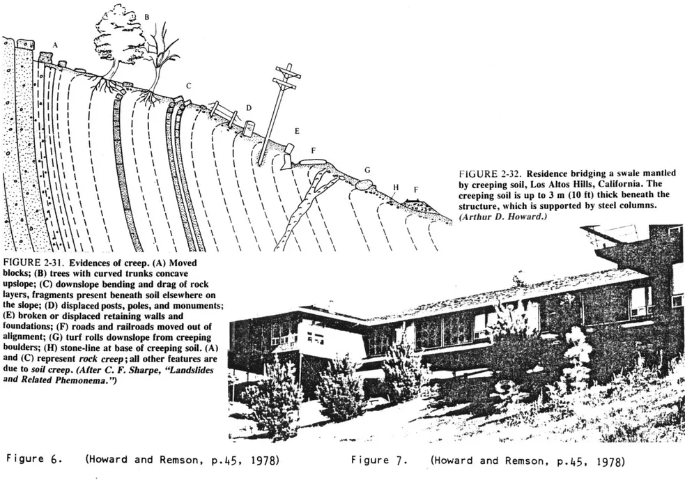
- \ \ \ \ 1* FIGURE 2-32. Residence bridging a swale mantled
- \ \\ \ \ \ I. H F by creeping soil, Los Altos Hills, California. The
- \ \ \creeping soil is up to 3 m (10 ft) thick beneath the structure, which is supported by steel columns.
-(Arthur D. Howard.)
FIGURE 2-31. Evidences of creep. (A) Moved
blocks; (B) trees with curved trunks concave upslope; (C) downslope bending and drag of rock layers, fragments present beneath soil elsewhere on
the slope; (D) displaced posts, poles, and monuments; t
(E) broken or displaced retaining walls and
foundations; (F) roads and railroads moved out of alignment; (G) turf rolls downslope from creeping boulders; (H) stone-line at base of creeping soil. (A) and (C) represent rock creep; all other features are due to soil creep. (After C. F. Sharpe, "Landslides and Related Phemonema. '9
GEOLOGY
M
The choice of foundation system depends heavily on the geology of the site. Geology is characterized by the soil(s) present; rock, clay, sand,..., and the process by which those soils came to be there. Their history determines
whether hillside soils will be stable, marginally stable, or unstable. Most
hillsides are in the marginal range of the stability continuum, meaning that there is a limit of safety for building. This is due to forces such as gravity perpetually acting to flatten the hills down. A slow process of change is everpresent.
Repercussions of even a small act can
spell disaster by accelerating the rate of change. Rock is the most stable
possibility, though even rock may have
fracture mechanisms which will cause collapse. Signs reading "Beware Falling Rock Zone" warn travelers daily of this type of danger. The stability of
hillsides tends to get worse as the angle of incline increases. A very good
synopsis of geology and mechanisms of slope failure is available in Abbott and Pollit (1980). It is important to
understand the geology before any changes are made to a site.
As an example of how understanding the geology can be addressed in a design to provide safety, the reader is referred to figure 6 which illustrates
characteristics of a creeping soil. A response sensitive to the presence of a creeping soil is shown in figure 7. The house hovers above the site allowing the soil to creep freely downhill. No common
intervention would survive the soil movement in such a situation.
WATER AND EROSION CONTROL
Dealing with water is one of the most important safety issues for a hillside building project. Geologic stability con be closely dependent on soil water content and water movement. Water moves down a hill in two ways, by flowing over the surface, or by slowly seeping
subterraneously. Erosion control is -mostly concerned with protecting the soil
from the action of surface water. Surface water is characterized by its' quantity and flow velocity. Quantity is generally controlled either by containment (storm drains), or diversion. Retention is also important in general, but may be difficult
on steep hill sites. Velocity is controlled by reducing the angle of
incline and/or increasing the roughness of the surface over which the water is
flowing. Large stones in a runoff channel slow down flow more than the smooth walls of a concrete culvert.
Since houses and driveways are impermeable to rain, runoff will be concentrated near the buildings,
increasing the potential for erosion. Once the erosion process has begun on a
steep hill, it can be very difficult, and perhaps impossible to stop. Slope
failures are much easier to prevent than to repair.
Foundation walls disrupt the flow of underground water, and if not provided with adequate drains, can act as dams, causing the build up of large hydrostatic
pressures, which may crack walls, topple walls, and aid in pushing buildings down the hill. Figure 8. The worst situation occurs when catastrophic failure is
induced, such as landslip. A good foundation does not cause an excessive change in the pressure distribution of the
hill. Draining away subterranean water prevents this danger. This process is the same for retaining walls. Without proper drainage, large overturning forces develop due to a combination of soil and
hydrostatic pressure. Perforations or weep holes in retaining walls allow water
to flow through. Water flowing under retaining walls promotes slope failure.
Generally it is beneficial to get water off the hill, but it is equally
important that there be enough water for the vegetation to grow, which is vital for
holding the soil in place. Native plants may be the best choice for erosion control
since they are adapted to climatic extremes.
soil
hydrostatic pressure
resultant pressure
(soil plus hydrostatic)
Figure 10. Progressively buried plinth (slopes under 100)
BUILDING SYSTEMS N
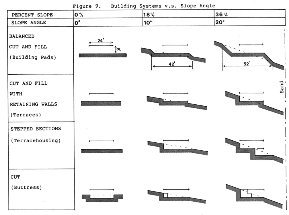
Building systems for hillsides are presented in figure 9. The matrix of Building Systems v.s. slope angle is organized in two parts: the first five approachs primarily alter the hill, while the last two, Pier and Grade Beam, and Pole, can be used to prop an existing
design up off the hill. Some gross limits imposed by geologic incompetency are
indicated, and impossible diagrams are omitted. An exhaustive survey of building methods v.s. the great variety of geologic
situations is beyond the scope of an architecture thesis.
Approachs to building on hillsides fall into three basic categories; altering the slope to suit an existing design,
propping an existing design up off the
hill, altering a design to fit onto a slope, or any combination of the three. Altering the slope yields savings in
design time, because an existing flatland design can be readily employed.
Propping an existing design up off the hill is a very common solution on slopes shallower than 100. It can be as simple as adding several extra courses of masonry, or as complex as building a
platform on which the house is placed. Often the building is placed on a plinth, which becomes progressively buried as it moves into the hill. Figure 10. The plinth resembles a wedge which makes up
the difference between the hill angle and the horizontal base of the house. As the slope gets steeper, past an angle of 20*, the advantages of simply altering the hillside become much less attractive.
Figure 9. Building Systems v.s. Slope Angle PERCENT SLOPE
SLOPE ANGLE BALANCED CUT AND FILL
(Building Pads)
CUT AND FILL WITH RETAINING WALLS (Terraces) STEPPED SECTIONS (Terracehousing) CUT (Buttress) 24' 4 2 fa '0' -7A=
58% 84% 119% oo% 300 400 500 90* >1 (a u-q u 0 .-4 r-4 0 Wj
Figure 9. Building Systems v.s. Slope Angle (continued)
PERCENT SLOPE 0% 18%/ 36%
SLOPE ANGLE d 10* 20'
FILL
PIER AND GRADE BEAM
POLE STRUCTURES (Propped Up) I I U. i ---- 4
1 11
71
1
1
IA,
Sand__ __ __ . Clay L"is*
Noemo gg SoiaRc00%
BALANCED CUT AND FILL
The simplest and cheapest alteration of a slope is the cut and fill building pad. Figure 11. A level shelf is cut into the hill, the grade change being
taken up in the form of steep embankments, uphill and downhill of the shelf. This method is limited to slopes of at most 300 by the natural angle of repose of the
particular soil(s) present. (1) Figure 12. This angle of repose can be extended a little by special treatment of
embankment surfaces. Normally a cut slope may be as steep as 45* whereas fill slopes are limited to 260 dependent on soil type. Construction of the cut and fill pad
(1)
Maximum grade for unmown planted banks is
50 - 60%, (270 - 30*),
Lynch and Hack, p.456, 1984
sandrained) (well drained) 33 compact clay (well drained) 45 loose clay -' (saturated) 25
sand or loam 50 bedrock 90
(forested) (consolidated)
65
Figure 12. Angles of repose for various types
of slope materials.
(Marsh, p.208, 1983)
n
Figure 13.
(This graph for
PRICES PER LINEAR FOOT FOR RETAINING WALLS
comparisons only, not for estimating.) 1. Gravity concrete with
vertical face
2. 2. Concrete cantilever
4.
/
3. Concrete cribbing4. Galvanized steel bin wall
5. Wood deck
6. Decorative stone wall 6' max. height 5. 6. 8. ... ... ... ... - .7... 4 8 12 16 7. Cut 8. Fill 20 450 1450 WALL HEIGHT IN FEET
500- 400- 300- 200-0 t1 0 0- 100-0
begins to get difficult at a slope of 90,
above which many pieces of mechanical
equipment cannot operate freely. (1) This inaccessibility contributes to higher
costs. As the slope gets steeper, the volume of soil involved increases and the extent of the excavation increases. On a
30* hill, half of the land affected is
left in an unuseable condition as steep banks, leaving half as level ground. This conservative estimate is based on
artificially increasing the angle of repose of the soil to 45*. Figure 13 illustrates the low construction costs of this simplest cut and fill method with other methods for establishing horizontal levels on a hill.
Typical sections from the City of
(1) Simpson and Purdy, p. 78, 1984
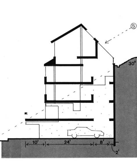
Brea, California's Hillside Policy study indicate that slopes up to 200 can be dealt with quite effectively at lower densities, (figure 14) though they discourage the use of building pads because they do not promote overlooking which provides uphill houses with an unobstructed view.
Visually a slope transformed into bulding pads can be detrimental to the overall landscape of a hillside, because the "alternating sequences of flatland and uniform banks results in monotony and
blandness." Figure 15. The resulting regularity clashes with the natural contours of a hill. It is at the point where new fill meets existing landscape that problems arise. (1) Care should be
2 'STORY WITH RETAIIMtJ6 WALL
FLJU- gETMNIk6 WIL
PLATFO'A FENAE
W11T kALf LOWER 6TRY
U
0
("I%
GPACIP gI4
-- ' Figure 14. Typical Sections for slopes under 20*
from the City of Brea Hillside Policy
Ei (Keith and Associates, 1975)
It'V
(sZ;)
Figure 15. Monotonous appearance of building pads (Victor Gruen Associates, p.36, 1965)
taken to disturb the existing landscape as little as possible and to blend in the cuts and fills.
This pad system requires changing the grade of large areas of the hillside, and obliterates much of the existing
vegetation. Selected trees can be
preserved, despite grade changes, but the techniques required can be costly and are usually awkward. Figure 16. Care must be taken to avoid erosion of newly made steep banks, which could be detrimental to
neighbouring areas both uphill and down.
N,
)
'C 'I.
I.
v1--,.
Figure 16. Technique for saving trees despite
regrading, requires an area equal to the projected crown of the tree.
Access in this kind of a system is akin to that in standard subdivisions. Public rights-of-way are generally no steeper than 10%, with notable exceptions
in California. The orientation of roads on steeper slopes will be generally along, or at a diagonal to the contours. This implies a need for long steep driveways to access individual sites, and an overall low density. Curbside parking will
increase the density to around 12
d.u./acre. See appendix figure 86. The low cost of creating a building pad may be offset by the high cost of the access road being divided among fewer buildings.
The pad method gives the freedom of orienting the house regardless of the contours, so good solar access should be
possible. The slope of the "level" part of the pad is under 10', so daylight
should be available on four sides of the house and on all levels. The system
requires a liberal amount of space on all sides of the house so privacy should be easy to preserve. As the slope gets
steeper, overlooking problems are minimized by long embankments between houses.
In general this method requires a radical change to hill contours. The problems associated with this system are exacerbated greatly as the slope gets
steeper, making this a minimal solution to building on steeper slopes.
Figure 17. House as outgrowth of retaining walls and terraces.
CUT AND FILL WITH RETAINING WALLS F!
A logical development of the pad method is to use retaining walls instead of banks to take up the grade changes. The construction cost of building
retaining walls is generally much higher than a pure earth moving operation. The use of terraces in conjunction with
retaining walls makes the site planning more sensitive to the contours of the hill because a smaller area is affected. This means that more of the hillside vegetation can be preserved. Since less of the hill
is affected, maintenance costs will be substantially reduced. (1)
It is easier to establish
relationships between terraces than
between pads because the terraces can be built closer together. This means the
site can be denser and more complex.
Banks can be used in conjunction with terraces to provide an interchange between builtform and landform. This will help make the building a part of the hill
landscape.
The ground levels and foundation walls inside the building are akin to terraces and retaining walls outside. This makes possible inside - outside
relationships and other continuities along the contours. The house can become an outgrowth of the retaining walls and
terraces. Figure 17. This concept of building generates a house whose interior
reflects it's nature of being built on a hill. A variety of terraces can appear in
the house in the form of level changes. (1) Victor Gruen Associates, p. 4 9, 1965
This provides added richness in section compared to letting the basement or lowest
level take up the change in grade. (Which is another option with this system.)
. As with any cut and fill method, the filled area will be more prone to settling than the cut area, since the cut area has had more time and pressure to consolidate. Careful compaction may solve this problem or it may be possible to site the building
exclusively on the cut area, leaving the filled area for use as outdoor space. Bearing can also reach down through the fill to undisturbed ground. Other
solutions to this problem include terraces made either only by cutting, or only by
filling. These will be discussed later. Figure 18.
Terracing with retaining walls will provide more flat useable space on a given
Emb C
b
a
Figure 18. Three basic configurations of
amount of sloping ground than the building pad method because the long embankments are no longer needed to absorb the change
in grade. The increased amount of useable space will help offset the cost of the retaining walls, especially if' land value is high.
The unit cost for retaining walls takes a jump at around 4' and another at around 8'. The savings on useable land gained by using retaining walls are
dubious if walls higher than about 8' are required. (1)
A unit cost analysis of retaining walls shows that at a slope of about 200 the cost of building a retaining wall begins to rapidly outstrip the cost of propping up a horizontal platform off the
hillside. Figure 19. Though these
numbers are for outdoor space, they should be reasonably proportional to indoor
construction, and provide a ballpark figure indicating when a designer should begin considering an alternative to a totally cut and fill system. The 20*
intersection point on figure 19 coincides with the 8' tall retaining wall on figure 13. Curiously, this is also close to the height of one story. If one were to build a 24' wide house, a standard width using two 12' x 2" x 12" joists end to end, and assumed the back wall was completely
buried, this would also correspond to a slope of about 200. It would seem that a different system is appropriate at angles steeper than this. The logical next step
is the stepped foundation. (1) Victor Gruen Associates, p.49, 1965.
19. UNIT COST ANALYSIS OF SLOPE ALTERATIONS I
Figure
11-0 DETERMINE BREAK EVEN ANGLE
estimating.)
Stone wall
26O
(This graph for comparisons only, not for
. Wood deck 1a t-t Vt, LII LMI 0 0 ,-3 0 I ~IV C:
z
ti 0 C-) LII tj 10 9-8 7- 6- 5- 4- 3- 2- 1-F ill1 2 Cut 161 I I I 20 SLOPE ANGLE 30(All values taken from 1985 Means Cost Data)
Wood deck
Fill
Cut
L
K
0
Sketch section of a hilltown, abstracted to
show tyical details.
Figure 20. Masonry bearing walls dictate slipping
vertical volumes. (Carver, p.118, 1979) q
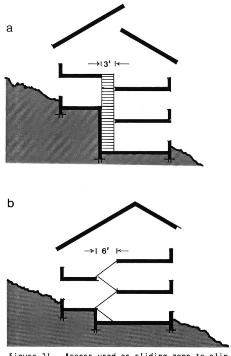
STEPPED SECTIONS
Stepping the section means splitting it's volume into two or more parts and offsetting them vertically. This vertical
slippage can take place as a level change in a room, along a wall as in typical Spanish masonry construction (figure 20), or perhaps most easily along an access zone. The sliding zone can be of varying width when used as an access. The two most common widths are 3' and 6' as shown
in figure 21. Six feet is half the run of a standard flight of stairs in a house
with a floor to floor height of 9'. The split in the section can be an opportunity for visual, accoustic and physical
connections between differentlevels. It can also serve as an organizer for the building.
b
Figure 21. Access used as sliding zone to slip
volumes vertically.
M
a
1 6' 14-4000
-+3'1+-a
b
r
C
d
-I
Figure 22. Variations of stepping sections.
A stepped section can be effective for lighting the backside of the hillside
house, which tends to become buried as the house is set deeper in the hill. Figure
56. Though this buried condition may be appropriate for some uses, such as furnace
rooms, it may result in other unfortunate spaces that need light. Furnaces do not require much space in a modern house. The need for spaces without windows is
generally low, though some spaces may be successful without them. The approach of zoning spaces by their need for daylight
is certainly a valid approach, and is
commonly used in many apartment buildings. The slope is an opportunity, however, of making housing which does not resemble apartment buildings.
Stepping the section generates several basic variations at the ground
level. Figure 22. While many of these variations may allow lighting of the backside of the house, they may conflict with a desire to have single level floors. Single or through level floors might be desirable in elderly housing for example. There are several ways of providing
through levels despite changes in section where the building meets the ground. The easiest situation is when the section is stepped by a full level as in figure 22a. Light can also be admitted by adding
ceiling height along the back wall which will allow high windows to be installed. Figures 22 b,c,d. Figure 22d shows a method of resolving the split level
section which creates a tall space on the second story with a view out over the hill.
Figure 23. Modular stepped footings and split
level house.
Figure 24. Modular stepped footings with single
level house.
can vary from 6" to over a story in
height. The modular stepped footing used by Spexarth is an appropriate way of
building in small changes of level. (see appendix) It allows the floor to be
closely fit to the contours of the hill. The result might be a series of small
interior level changes, ranging in size from 6" to 24". The system can be used to create a split level house on slopes under
30. Figure 23. On slopes of about 10*
and under, it is possible to establish a single level house, with the odd
underneath space left as slack, or as a progressively buried plinth. Figure 24. A secondary system must be introduced to take up the slack between the footing and the floor levels.
Perhaps the biggest advantage of this system is that it allows for on site
SECTION
Figure 25. Ranch house stepped up the hill.
alterations. This means the design need not be tightly tailored to the site.
Half level steps can be used to get light in without losing the sense of the
larger space. Steps of this size are
compatible with a method for adapting a standard single story ranch house design to a hillside site. The ranch house is basically segmented along it's length with
the pieces stepping up the hill. Figure 25. (1) Part of the appeal of a single
story ranch house is that the ceiling of every room is the bottom of the sloping roof. These spaces are more interesting than the boxlike spaces typically
generated in multi-storied buildings. If the typical ranch house is stepped up the hill room by room, the room-roof
relationship is retained, the living pattern and room layout remain the same, and the access or corridor is transformed
into a series of stairs and landings. This could be a very appropriate form for
low density housing, and an interesting twist on a standard living pattern. This stepping technique can also be used
emanating downwards from the access. It also provides a method of
orienting the house perpendicular to the contours without requiring large
excavations, thus passing the criterion of
minimizing change to the hillside. Since the bulk of the house would be up the hill, the street could have a more open
feeling. Zero lot line housing might also be adapted in this way. The modular
stepped footing would be very compatible with this system. Expressing the stepped nature of the house can be very effective. Figure 26.
Figure 26. External expression of stepped footings.
Designer Harwell Hamilton Harris. (Sunset Ideas for Hillside Homes, p.20, 1961)
The option of stepping by whole floors begins to be useful around 250 - 30*.
This may result in the small lowest level being lit on one side only, or in the floors beginning to terrace up the hill and being lit generally on three sides only. Terracing floor by floor up the hill generates the Terracehousing form which has been used frequently in Europe, consisting of apartment flats stepping up the hillside. Figure 27. (1)
When a house is oriented
perpendicular to the hill contours, it is possible to step the bottom of the house while leaving the top floors unstepped.
(Many municipalities have 35' height limits which will restrict this). The
Figure 27. Terracehousing
(Riccabona and Wachberger, p.14, 1972)
full top floor provides lots of space and the possibility of entering the main
uppermost living area on a single level from the car or street access. Figure 28. This is a typical situation in the rim
type house which is built "over the edge"
on the steep part of a slope, next to a
flat shoulder. This type of siting leaves the flatter part of the site for yards and access. Building perpendicular to the contours leaves the long sides of the
(1)
See bibliography for references to Terracehousing
Figure 28. Entry on a single level from uphill.
Figure 29. Stepping down mass of house to avoid
tall, blank downhill wall.
house open to light. Visually the downhill end of the house may be quite tall against the hill. Stepping the
downhill mass of the house down can soften this intrusion. Figure 29.
Stepped sections are intrinsically more sensitive to steeply sloping sites because they respond internally by
splitting levels, which reduces the need to change the hill. The use of a split level house means a large reduction in excavation over a pure cut approach such as in the buttress system. Accordingly there is less fill to be hauled off the site, or stabilized on site. The shorter retaining walls are less expensive and easier to engineer than the taller
counterfort type of the buttress system. The shallower excavation may also be less disruptive to subsurface water flow.
In general, split and multi-level
houses are considered desirable. In fact, they can be found built on completely flat sites. It makes sense to take advantage of the need for multiple levels in the house generated by the sloping nature of the site.
Figure 30. Technique for lighting a single aspect house.
CUT or BUTTRESS F1
This method consists primarily of making a major cut into the hill and
supporting the hill with large
counterforts or buttresses. It requires a
radical change of the hill and, as the slopes get steeper, a large scale
intervention to prevent slope failure. This system might be necessary if one needed to maximize flat space at the toe
of a hill or if one had a building site
uphill of the access road. In both these
cases, the major motivators for using this system are providing parking, and access
to a front door(s) at a distance not too far removed from the street. In most
cases the use of this type of system will mean that the front door is at least one flight up from the street.
Lighting the buried edge is always a problem with this system. Figure 30. If one wall with no windows is satisfactory
to inhabitants, space planning is simple with this system, and it can be seen as
one half of a double loaded corridor apartment bu'ilding.
The possibility of using the buried edge of the building for light and access exists. A 6' to 8' wide zone separating the building from the hill will provide plenty of room for light wells, elevators, and bathrooms. The resulting spaces, lit
indirectly from the side or from above could be quite nice. This system might also be useful for bringing in light on a difficult North facing slope.
The buttress system tends to generate a vertically organized building, resulting in a potentially large number of stairs to
-~
U'
U,
L
a
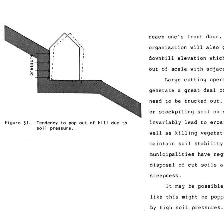
Figure 31. Tendency to pop out of hill due to
soil pressure.
reach one's front door. This vertical organization will also generate a tall downhill elevation which may tend to be out of scale with adjacent streets.
Large cutting operations will generate a great deal of soil that may
need to be trucked out. Simply spreading, or stockpiling soil on slopes will
invariably lead to erosion problems, as well as killing vegetation needed to maintain soil stability. Some
municipalities have regulations requiring disposal of cut soils as related to slope steepness.
It may be possible that a structure like this might be popped out of the hill by high soil pressures. Figure 31. The
extent of excavation 4
soil entrained
a
Figure 32. Two possible ways of entraining soil mass to increase foundation stability.
technique might still work if surrounding soil was entrained, made part of the
structure, by the foundation somehow.
Figure 32. Two possible techniques are suggested here, but a geotechnical
engineer would have to be consulted.
-epo
Ok
Figure 33. Methods for
A.) Vertical wall
hill by brute B.) Inclined wall soil angle of increasing stabil holds up force. increases repose.
ity of tall retaining wall.
C.) Stepped, inclined wall reduces pressure further. D.) Vertical steps make this
a cousin to Terracehousing.
A modification of the vertical back wall can greatly improve improve its stability and reduce its cost! (1) In this modification, the back wall leans into the hill. Figure 33b. The behaviour
of a leaning back wall is to increase the angle of repose of the soil, as opposed to simply holding the soil up which is what the vertical back wall does, by dint of brute engineering. Figure 33a. A further modification is to step the tall back wall
into the hill which brings the angle of
-
0 N. VF:
up we, k Q,-a
b
C
the wall even closer to the angle of repose of the soil. Figures 33c,d.
Architecturally, this sloping back wall provides a space between the back of the building and the face of the hill, providing an opportunity to bring light
in. This opportunity is created by separating the tasks of forming a back wall for the building and holding back the hill. The extra space captured can also
be used for living, making this a cousin to the Terracehouse. Added advantages of this separation of hill support and
closure are that the space can be used to collect seepage from the hill, or as a place to run utilities, sewerage, etc.
It is not clear- what the requirements and cost of backfilling and compacting backfill on a buttress project would be. Advantage might be taken of this
backfilling/excavation dilemma to provide level outdoor space uphill of the
structure since the soil would have already been greatly disturbed. Figure
34. This uphill area would be quite
removed from the street and very private. It would also serve to protect the house from minor landslides on the slope above.
One intriguing aspect of using a buttress system is the opportunity and challenge to make the buttress into an exciting architectural element within the building. It might take on many shapes and could be perforated to a small extent for openings. The buttress would also provide a large amount of thermal mass.
A limiting constraint of a buttress system may be the spacing required between the buttresses. If this spacing is less
/
I
AL-VI
L
L a-I-Figure 34. Establishing space uphill of the house
on disturbed soil. Buttress can become
an exciting architectural element.
with. A system of horizontal ribs will add some design flexibility by increasing the distance between buttresses. The
resulting dark 2' to 3' zone could be used for closets, bathrooms, etc. Figure 35. The buttresses should definitely be of
fireproof construction.
On shallower slopes, up to about 200 (36%) a cut system can be used to build earth sheltered buildings. Above this slope, second floor windows may become buried, and the energy saving benefits of earth sheltering begin to diminish
relative to the value of getting daylight in.
The buttress method has several advantages and disadvantages. Radical
changes to the hill are expensive, difficult to build, and the long term, even the short term stability may be
questionable, depending on geology. The process of digging a large hole on some slopes may cause massive undermining, thus construction of buttresses is limited to
slopes of perhaps 300.
Figure 35. Horizontal ribs increase buttress
spacing and provide 2' of storage
space. 8' zone for light, access,
This building system consists of hauling in campactible soil, and using it to build up level ground. It is similar to the Pad method previously discussed, except that there is a minimum of cutting
into the slope. It is an expensive system due to costs of delivering fill to the
site and compacting it. The fill can be left to assume it's natural angle of
repose or contained with a retaining wall. The use of retaining walls will limit the amount of the hill which is affected.
Equally important, the use of the
retaining wall will limit the quantity of fill which is required. The cost of the fill is thus reduced while the cost of the retaining wall is added on. To minimize cost shallower fill volumes should be
Generally there must be road access for the large trucks in which the fill is typically delivered. These trucks require a large space for turning around, which may be a limiting constraint on steeper slopes.
This system is rarely used exclusively. It is often used in
conjunction with other systems, usually to provide access for automobiles. It is primarily used as part of a cut and fill operation.
On shallower slopes this system might be used to create a building pad whereas on steeper slopes (over 20*) it is more likely to be used as part of a stepped foundation. The value of using this
system on slopes steeper than 200 or maybe
300 , is questionable both because of costs
and problems with stability. On flatter slopes this system can be used to raise the elevation of buildings.
A major advantage of this system is that it allows close control of the fill. This may be important for drainage and or soil compactibility. It also has an
advantage over a cut and fill system in that there is no need to stockpile large amounts of fill which tend to clutter up the site. This avoids all the problems of erosion control during construction. The vegetation is also saved from being buried under piles of fill.
Another advantage of a fill system is that it may obviate the necessity of
bringing heavy equipment out on the slope. The soil can be delivered by crane, chute, or conveyor. Compacting can be done by hand, and concrete can be pumped. This
approach would be quite sensitive to the issue of landscape preservation. On large scale projects it might be quite costly.
I I
I;
Figure 36.
I.
I,
PIER AND GRADE BEAM FOUNDATION ni
-"This type of foundation links a poured concrete perimeter footing to the ground with a matrix of grade beams and concrete piers, some up to 20' in depth. The resulting grid grips the hillside like the roots of a giant tree. Slopes in excess of 450 can be built on with this
kind of foundation. And in areas where there are landslides, expansive soils or earthquakes, a pier and grade beam
foundation may be required by local building code."- Figure 36. (1)
The holes for the piers must be
drilled. The process of drilling the pier holes generates a certain amount of fill which may need to be trucked out. On
steep slopes, the drill rig is tied off (to a tree or perhaps a large stake) at the top of the slope and winched up and down the slope like a yoyo. The rig
itself is heavy (often about 12 tons), and tends to squash and shift the first
several feet of topsoil downward. One must therefore consider the access route of the drill rig. It is advantageous to
keep the drill rig, and any other heavy equipment for that matter, off the site, but this is generally impossible. The drill rig is usually confined mostly to
the area which the house will cover. Areas around the house, along with their vegetation, can be left untouched. (1)
(1)
Truck mounted drill rigs can operate on slopes up to 30 degrees and do less damage to the slopes than the tractor or crawler mounted auger which can operate on a slope up to 45 degrees.
This type of foundation is not level, but approximates the contours of the hill. A secondary system, such as a stud wall,
is often used to make the transition to the horizontal, (not unlike a
progressively buried plinth). This system is used commonly in California.
The underlying reasons for using Pier and Grade Beam foundations are that they eliminate most of the costs of cutting and filling, and hauling soil to and from the site. Much of the construction is done by hand, so excessive destruction of the
slope caused by excavation equipment is avoided. As discussed earlier,
alterations of slopes steeper than 200 to 30* may prove extremely difficult, as well as creating a potentially hazardous
situation. For the most part, it is easier to preserve the natural state of
the site.
Pier and Grade Beam foundations can be built on slopes of up to maybe 500 in sturdy soil. (1) Thus they offer great opportunity and flexibility on the more difficult, steeper slopes. The building system does not extend up into the house, and thus imposes few restrictions on the architectural design. The use of a grade beam makes the foundation compatible with a system of bearing walls or point loads over piers. The house can have either a stepped section or through levels.
A system which would work well with a Grade Beam foundation is a series of
wooden bents, as used in traditional timber framing. Wooden bents could be
(1)
Estimate based on personal correspondence with M. Spexarth.
made which were taller on the downhill side. They could easily negotiate the change in grade, and merge a traditional, well understood, building system with a new foundation type. Figure 37. The value of adapting an established building system is that the builders already
understand it. They will be more
comfortable with a new technology if it encompasses something which they are already familiar with.
Downslope sites are less difficult than upslope sites. Spexarth's rule of thumb is that a foundation on a downslope will cost twice as much as a foundation on level ground and an upslope site will cost three times as much. This may be partly due to the fact that building materials are easier to move downhill than uphill.
Both the Pier and Grade Beam
tigure 3/. Iraditional timber framing would work
well with a pier and grade beam foundation.
(Timber frame after Benson, T., F.H.B. #16, p.38, 1983)
foundation and the next to be discussed Pole foundation system disassociate the horizontal levels of the living space unapologetically from the hillside. This behaviour inherently has less of an impact on the hillside.
S81bearns
at first and third floors
9.
j4
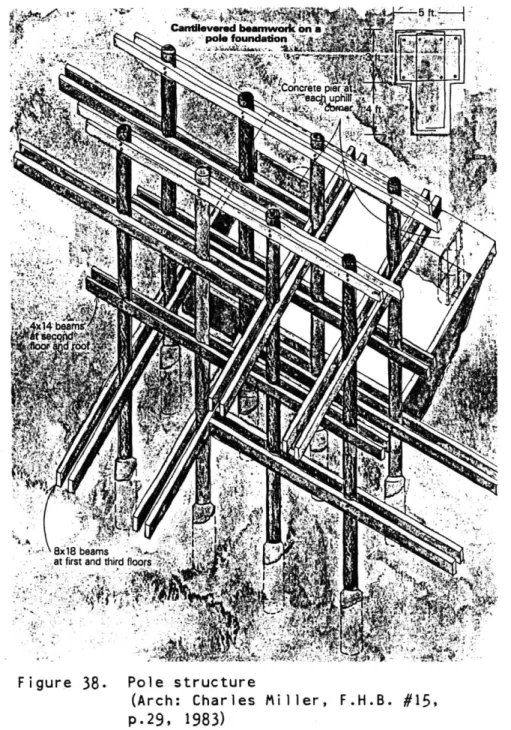
Figure 38. Pole structure
(Arch: Charles Miller, p.29, 1983)
POLE STRUCTURES
M
This building system consists of a grid of poles set directly in the ground. The poles are set in a manner similiar to the one used in setting telephone poles. Figure 38. The living space is then
suspended from this artificial forest. Poles offer great flexibility for building on hills. They can negotiate slopes at least as steep as 45* (10 in 10). The steepness of the slope which can be built upon is a function of the pole length and the buckling strength of tall poles. The steeper the slope, the taller the poles. Poles can be obtained in excess of 100' in length.
There is much freedom in both the horizontal and vertical dimensions, thus making the system very Corbusian in
nature. The plans and the sections can be very free from the structure. The
freeform and whimsical designs which can be constructed using this system attest to this flexibility. Figure 39. Using
poles, a horizontal platform can be easily established, relatively independent of slope steepness or contour irregularities. The elevations of the floor levels can be adjusted, simply by attaching the
crossbeams higher or lower. A large number of different levels are possible. Cantilevering the main crossbeams provides low cost options for more living space and/or outdoor decks.
The walls are not load bearing in this system, so some shear resistance must be built in to resist wind loads. (1) The
Figure 39. Pole foundations enable freeform design. (Arch: Charles Miller, F.H.B. #15,
L -J LJr garage/ kitchen/ dining level road liv'ng / bedruon level studio/ plav level
Figure 40. Goldwater Canyon, Beverly Hills, U: m
California, Arch: Helmut Schulitz.
7
-I
Figure 41. Concrete frames can easily negotiate
grade changes. Beach house for
Dr. P. Lovell. Newport Beach, 1925-6,
Arch: R.M. Schindler (Gebhard, p.84-85, 1972)
I
I
Y rj'~
embedded poles may provide quite a bit of wind resistance, but possibly not enough to avoid uncomfortable sway. (1)
A three dimensional design grid can be used to design pole structures. This Goldwater Canyon housing project shows the possibilities of such a grid and it's
compatibility with prefabricated
construction. Figure 40. Note that this structure is actually a hybrid of Pier and Grade Beam below ground, with a pole
structure above.
A poured concrete pole structure might easily grow into a series of concrete bents or frames, among which
floor levels would be supported.
Schindler's Beach House for Dr. Phillip
(1)
For a more complete discussion of pole building the reader is referred to Merrilees, 1980.
Figure 42. Bulkheads support housing
Arch: Erwin Muhlestein, Switzerland (Riccabona, p.39, 1972)
Lovell illustrates this possibility in a situation where the building needed to be off the ground because of it's location. Figure 41. There is good potential here for use on hills. This system would also work with a grade beam foundation. If the
concrete frames were solid, they would behave like bulwarks, giving shear resistance to brace structures on the hill. Bulwarks would require excavation and perhaps conventional footings. Figure