Publisher’s version / Version de l'éditeur:
Proceedings of the Ultrasonics Symposium 2006, 2006-10-03
READ THESE TERMS AND CONDITIONS CAREFULLY BEFORE USING THIS WEBSITE.
https://nrc-publications.canada.ca/eng/copyright
Vous avez des questions? Nous pouvons vous aider. Pour communiquer directement avec un auteur, consultez la première page de la revue dans laquelle son article a été publié afin de trouver ses coordonnées. Si vous n’arrivez pas à les repérer, communiquez avec nous à PublicationsArchive-ArchivesPublications@nrc-cnrc.gc.ca.
Questions? Contact the NRC Publications Archive team at
PublicationsArchive-ArchivesPublications@nrc-cnrc.gc.ca. If you wish to email the authors directly, please see the first page of the publication for their contact information.
NRC Publications Archive
Archives des publications du CNRC
This publication could be one of several versions: author’s original, accepted manuscript or the publisher’s version. / La version de cette publication peut être l’une des suivantes : la version prépublication de l’auteur, la version acceptée du manuscrit ou la version de l’éditeur.
Access and use of this website and the material on it are subject to the Terms and Conditions set forth at
Integrated and Flexible Piezoelectric Ultrasonic Transducers
Jen, C.-K.; Kobayashi, M.
https://publications-cnrc.canada.ca/fra/droits
L’accès à ce site Web et l’utilisation de son contenu sont assujettis aux conditions présentées dans le site LISEZ CES CONDITIONS ATTENTIVEMENT AVANT D’UTILISER CE SITE WEB.
NRC Publications Record / Notice d'Archives des publications de CNRC:
https://nrc-publications.canada.ca/eng/view/object/?id=63cc9ccc-fed6-49a4-9ad7-10fbe77171f2 https://publications-cnrc.canada.ca/fra/voir/objet/?id=63cc9ccc-fed6-49a4-9ad7-10fbe77171f2
Integrated and Flexible
Piezoelectric Ultrasonic Transducers
C.-K. Jen and M. Kobayashi
Industrial Materials Institute, National Research Council Canada Boucherville, QC, J4B 6Y4, CANADA
(cheng-kuei.jen@cnrc-nrc.gc.ca)
Abstract— Thick (>40µm) ceramic films as piezoelectric and ultrasonic transducers (UTs) have been successfully deposited on metallic and non-metallic substrates by a spray technique. In the film fabrication a composite consisting of piezoelectric powders well mixed with solution of high dielectric constant is directly sprayed onto the substrate. It is then dried, fired or annealed by heat. Multiple coating is used to achieve preferred thicknesses. A corona poling is utilized to achieve the piezoelectricity of the film. The top electrode is accomplished by a painting method. All fabrication processes can be carried out on-site and by handheld devices. Integrated ultrasonic longitudinal, shear, surface and plate wave transducers have been made. The same technology has been also used to fabricate flexible transducers consisting of a thin substrate, a piezoelectric ceramic film and electrodes. The flexibility is realized owing to the porosity of piezoelectric film and the thinness of the piezoelectric film, substrate and electrodes. All transducers have been tested at least up to 150°C. Their applications for non-destructive testing of different materials are demonstrated.
Keywords-piezoelectric/ultrasonic transducers; high temperature, bulk, surface and plate wave transducers, nondestructive testing, flexible transducer
I. INTRODUCTION
Non-destructive testing (NDT) of materials are commonly performed to identify, characterize, assess voids, defects and damage in metals, metal alloys, composites and other materials [1,2]. Furthermore, the increasing demand to improve the performance, reduce downtime, increase reliability and extend the life of transportation vehicles, structures and engineering systems, requires the use of systems that have integrated capabilities with built-in sensors that perceive and process in-service information and take actions to accomplish desired operations and tasks [3-6]. It is established that ultrasonic methods are widely used for real-time, in-situ or off-line NDT and evaluation of large metallic and polymeric composite structures including airplanes, ships, automobiles, pressure vessels and pipelines [5,6]. Because of their subsurface inspection capability, elastic property characterization ability, fast inspection speed, simplicity and cost-effectiveness [1-15], there has been considerable interest in ultrasonic NDT [5-15]. In many applications, ultrasonic inspections may need to be applied to curved surfaces or complex geometries [1,2,5,6]. It is known that conventional planar ultrasonic transducers (UTs) show poor inspection
performance on curved surfaces. Also applications may often be subjected to high temperature (HT) environments [7-15]. Common limitations of current piezoelectric UTs are (a) lack of suitability for use on curved surfaces and (b) the difficulty for use at temperatures higher than 100°C. Therefore the objective of this investigation is to develop integrated longitudinal (L), shear (S), Rayleigh surface (RAW) and Lamb plate acoustic wave (PAW) transducers and flexible HTUTs operated at least up to 150°C. NDT of different materials employing these HTUTs will be demonstrated.
II. FABRICATION AND CHARACTERIZATION
In this study thick (>40 µm) piezoelectric ceramic films as UTs are of interest. These films can be made by the technologies of jet printing [16,17], screen printing [18,19], tape casting [20,21], dipping [22,23], hydrothermal method [24,25], etc. Here an alternative sol-gel spray technique is used [14,15,26]. The ball-milled sub-micron piezoelectric lead-zirconate-titanate (PZT) or bismuth titanate (BIT) powders were dispersed into PZT sol-gel solution. The PZT and BIT powders were chosen because of their high piezoelectric constant and high Curie temperature (675°C), respectively. The final PZT/PZT or BIT/PZT mixture (paint) was then sprayed directly onto selected metallic substrates, such as stainless steel (SS) and aluminum (Al) alloys through an airbrush. With this sol-gel spray technique, the films can be produced at desired locations using a paper shadow mask. After spraying the coating, thermal treatments such as drying, firing and/or annealing were carried out using a heat gun. Multiple coatings were made in order to reach desired film thicknesses. In this study the film thickness is between 40 and 120µm. Piezoelectric films were then electrically poled using
a corona discharging technique. The corona poling method was chosen because it could pole the piezoelectric film over a large area with complex geometries. Finally, silver paste, platinum paste or silver paint spray method was used to form the top electrodes at room temperature.
The measured relative dielectric constant of the PZT/PZT film and BIT/PZT film was about 320 and 80, respectively. The d33 measured by an optical interferometer is 30 (10-12
m/V) for PZT/PZT and 10 (10-12 m/V) for BIT/PZT. The electromechanical coupling constant measured was 0.2 for PZT/PZT and that for BIT/PZT was weaker.
III. INTEGRATED LONGITUDINAL AND SHEAR WAVE
TRANSDUCERS
Various efforts have been devoted to the development of piezoelectric HTUTs of large bandwidth and high efficiency [7-13] and they may be supplied by several companies. However, the reported efforts have so far devoted to L wave UTs only. In [14,15] the integrated L wave HTUTs have been reported, however, it is understood that S waves may be advantageous over L waves for NDT and characterization of materials because liquid and gas medium do not support S waves. In addition, for the evaluation of material properties, sometimes it is important to measure shear modulus and viscoelastic properties in which S wave properties are a requisite. Furthermore, a HTUT setup to generate and receive both L and S waves at the same sensor location would be also of interest.
The mode conversion from L to S wave due to reflection at a solid-air interface was reported [27,28]. It means that the L wave UT together with L-S mode conversion caused by the reflection at a solid-air interface can be effectively used as a S wave probe as shown in Fig.1. In Fig.1, Li waves generated by
an L wave UT reach a solid-air interface and reflected as Lr
and Sr waves. The equations governing the reflection and
mode conversion with respect to the L wave incident angle θ can be given in Eqs. (1)-(3) [29], where Vl and Vs are L and S
wave velocities in the solid, respectively, and Rll and Rsl are
energy reflection coefficients of the L and S waves, respectively. Li Lr Sr θ θ ϕ Air Solid Interface Li Lr Sr θ θ ϕ Air Solid Interface
Fig.1 Reflection and mode conversion with an incident longitudinal wave at a solid-air interface. ϕ θ sin sin
V
V
l = s (1)(
)
(
)
2 2 2 2 2 2 sin 2 sin 2 cos 2 sin 2 sin 2 cos ⋅ ⋅ + ⋅ ⋅ − = θ ϕ ϕ ϕ θ ϕV
V
V
V
R
l s l s ll (2)(
)
(
)
[
2 2]
2 2 2 2 sin 2 sin 2 cos 2 cos 2 sin 2 cos 4 θ ϕ ϕ ϕ θ ϕ ⋅ ⋅ + ⋅ ⋅ ⋅ =V
V
V
V
R
l s sl l s (3)In this study, a mild steel with the L wave velocity Vl =
5900 m/s and S wave velocity Vs = 3200 m/s at room
temperature was used as the substrate. Fig.2 shows the calculated energy reflection coefficient based on Eqs. (2) and (3) for the mild steel substrate. It indicates that the maximum energy conversion rate from the Li wave to the Sr wave is 97.5
% at θ = 67.2°, and the reduction of the energy conversion rate is within 1% in the θ range between 60.8° and 72.9°.
0 30 60 90 0.0 0.2 0.4 0.6 0.8 1.0 E n erg y R ef lec ti o n C o ef fi ci en t
Angle of Incidence (degree)
Rsl Rll
θ
:
0 30 60 90 0.0 0.2 0.4 0.6 0.8 1.0 E n erg y R ef lec ti o n C o ef fi ci en tAngle of Incidence (degree)
Rsl
Rll
θ
:
Fig.2 Energy reflection coefficient vs. θ (incident angle)
L UT Li Lr Sr ϕ θ θ θ Probing End L UT Li Lr Sr ϕ θ θ θ Probing End (a) Probing End L UT 38mm 25mm 25mm 61.5° Probing End L UT 38mm 25mm 25mm 61.5° (b)
Fig.3. (a) Schematic diagram and (b) actual device of an integrated S wave UT probe with the L wave UT is located in a plane parallel to the direction of mode converted S wave where θ = 61.5°.
In order to achieve S wave HTUTs firstly we fabricated the 100µm thick BIT/PZT film L wave UT using the sol-gel spray technique described in Section II. Let this L UT be in a plane parallel to the mode converted S wave direction as shown in Fig. 3(a). This approach could reduce the machining time of the substrate and thick UT film fabrication difficulty. The top electrode was made by platinum paste which can sustain the temperature up to more than 450°C. By considering this criterion, θ +ϕ is required to be 90°. From Eq. (1), which is the Snell’s law, we can obtain θ = 61.5°. At this angle, the conversion rate is 96.7% that is only 0.8% smaller than the maximum conversion rate at 67.2°, based on the result in Fig. 2. Therefore, Figs. 3(a) and 3(b) show the design schematic and actual device developed for this study, respectively. Figs.4(a) and 4(b) show the ultrasonic signal in time and frequency domain, respectively, of the received Sr
wave in the pulse-echo mode at 350°C. The Sn represents nth round trip of the S wave echoes traversing back and forth between the L UT and the probing end in Fig. 3. The center frequency of the S1 echo was 6.7MHz and the 6dB bandwidth was 3.8MHz. The signal-to-noise ratio (SNR) of S1 echo was about 30dB. The SNR is defined as the ratio of the amplitude of the S1 echo over that of the undesired signals between the Sn echoes in Fig. 4(a). The signal strength of the S1 echo at 350°C was 5dB smaller than that at room temperature. It can
1120 2006 IEEE Ultrasonics Symposium
be seen that the received L wave is not visible due to the fact that the dimension of the substrate has been chosen so that the reflected L wave from the probing end does not enter into the aperture of the L UT.
20 40 60 80 S3 S2 Am p li tud e ( a rb. uni t) Time Delay (µs) S1 (a) 0 5 10 15 20 A m p li tude ( a rb. uni t) Frequency (MHz) S1 S1 0 5 10 15 20 A m p li tude ( a rb. uni t) Frequency (MHz) S1 S1 (b)
Fig.4 Ultrasonic signal in (a) time and (b) frequency domain of the S wave UT probe shown in Fig.3 at 350°C.
If one would like to generate and receive both L and S waves at the same time, then the S wave probe shown in Fig. 3 can be modified to achieve such a purpose. In fact, it simply makes a slanted surface with an angle 45° from the intersection of the slanted plane and the line from the center of the L UT as shown in Fig. 5(a). The 45° angle plane will reflect the energy of the Li wave into the Lr,45° wave normal to
the probing end as shown in Fig. 5(a). Therefore, in principle, the upper part of the L wave, generated from L UT, can be used to produce the Sr wave and the lower part to produce the
Lr,45° wave. Fig.5(b) shows an actual device developed. Fig.6
shows ultrasonic signal in time domain in the pulse-echo mode at 350 °C, in which the Sr (S1) and Lr (L1) waves are
observed simultaneously. The L1 represents the first round trip L wave echo traversing between the L UT and the probing end. The center frequencies of the S1 and L1 echoes were 7.0MHz and 7.0MHz and the 6dB bandwidths were 3.0 MHz and 3.8MHz, respectively. During the top electrode fabrication for the device shown in Fig. 5(b), the area of the top electrode was adjusted so that the amplitude of the reflected Sr and Lr,45° waves were nearly the same. The SNR
of the L1 and S1 was about 20 dB.
L UT 45° Li Lr Sr Lr, 45° θ ϕ θ θ Probing End L UT 45° Li Lr Sr Lr, 45° θ ϕ θ θ Probing End (a) Probing End L UT 38mm 25mm 25mm 61.5° Probing End L UT 38mm 25mm 25mm 61.5° (b)
Fig.5 (a) Schematic diagram and (b) actual device of an integrated L and S wave probe with the L wave UT located in a plane parallel to the direction of Sr wave. 10 15 20 25 30 35 S1 Am pl it u d e ( a rb . uni t) Time Delay (µs) L1
Fig.6 Ultrasonic signal in time domain of the L and S wave UT probe shown in Fig.5 at 350°C.
IV. INTEGRATED RAW AND PAWTRANSDUCER
For NDT applications there is a critical need for integrated in-situ sensors for local and global damage detection and assessment [3,4]. In the past the local aspect of the damage monitoring on metals and graphite/epoxy composites has been reported [14,15]. It is known that RAW and PAW transducers [27,30] can be used for NDT of metals such as SS and Al alloys in the range of several centimeters or meters depending on the attenuation characteristics of the substrates. In the common practice the L or S wave UTs and a wedge are used to generate and receive the desired RAW and PAW with the proper mode conversion inside and through the wedge [1,2]. However, there is a requirement of an ultrasonic couplant between the wedge and the sample under test. It is difficult to apply these UTs, wedges and couplants on curved surfaces and at HT. In this section, the purpose is to develop techniques for on-site fabrication of RAW and PAW transducers directly onto desired SS and Al alloy substrates for NDT applications at 150°C. Since pulse-echo modes are of interest for NDT applications, most of our measurement data will be shown for this mode although measurement data in transmission modes will be demonstrated as well. One goal is to use these structurally integrated sensors, to inspect, for example, in-flight aircraft critical components, thus increasing platform availability and reducing associated maintenance costs.
The fabrication processes of RAW and PAW transducers are the same as those for the fabrication of L UT except that the top electrode is made in a shape of interdigital transducer (IDT). Since in this study the desired RAW and PAW operation frequency range is between 0.5 and 2.0MHz, one mask used in this study is designed, fabricated by the electrical discharge machining (EDM) method and shown in Fig.7. The top and bottom connection electrodes parallel to the wave propagation direction are called bus-bars, the other thin electrodes perpendicular to the wave propagation direction are called fingers. The finger widths of the IDT are 0.5mm for the IDT. The separation among the fingers is also 0.5 mm wide. The mask is made of a 0.57mm thick SS plate. The thickness is chosen so that the mask is flat, has negligible shadow effect during the colloidal silver spray and is reusable. Such finger width is convenient for the colloidal silver spray method. This IDT fabrication technique makes the selection of finger size and sensor size simple and convenient.
Bus-Bar
Fingers Bus-Bar
Fingers
Fig.7 Mask of an IDT pattern.
A. Integrated ultrasonic transducer on Al alloy substrates for RAW and PAW measurements
Al alloys are common materials for aircraft structures and other transportation systems, such as automobiles. A 25mm-thick Al alloy plate is used here for RAW experiments. Two IDTs were made on top of the 86µm-thick PZT/PZT film by the colloidal sliver paint spray. The thickness was about several microns. Fig.8 shows the integrated PZT/PZT composite film transducer with the IDT near edge “A” operated in the pulse-echo mode at 150°C. The limitation of 150°C came from the consideration of the 350°C Curie temperature of PZT/PZT composite films and sprayed colloidal silver paint IDT electrodes. The measured RAW signals in time domain with a band pass filter between 0.5 MHz and 2.0MHz is given in Fig.9. In Fig.9 RA, RB and RA+B
are the reflected echoes either from the edge “A” or the edge “B” through the corresponding Rayleigh wave travel paths (distances) of 2A, 2B, 2(A+B), respectively. The longest travel distance in this figure was 306mm (for RA+B). The two
edges can be considered as large deep defects (cracks) in practical NDT applications. It means that this integrated RAW transducer can be regarded as a good NDT tool at 150°C for a sensing distance of 306mm (e.g. RA+B). The noises in Fig.9
came from the scattered bulk waves from the lower corners of the two edges of the Al alloy substrate. It is noted that when both IDTs shown in Fig.8; one as the RAW transmitter and another as the receiver, are used, transmitted RAW can be obtained. The IDT near edge “B” can be also operated in the pulse-echo mode.
At room temperature the measured L wave velocity Vl
and S wave velocity Vs of this Al alloy substrate are 6343m/s
and 3044m/s, respectively. Using these data the calculated RAW group and phase velocity VR is 2846m/s. It is noted that
for isotropic substrates the phase velocity is equal to the group velocity [27,30]. At room temperature the measured VR is
2840m/s which agrees well with the theoretically calculated value. At 150°C, as shown in Fig. 9, the measured RAW velocity is 2700m/s and the signal strength at 150°C is 13dB weaker than that at room temperature. The reason of this high attenuation at 150°C is being investigated.
37 mm 91 mm Aluminum Block (25 mm Thick) IDT Electrical Probe Edge A Edge B IDT 25 mm 37 mm 91 mm Aluminum Block (25 mm Thick) IDT Electrical Probe Edge A Edge B IDT 25 mm
Fig.8 A 25mm thick Al alloy plate with an IDT RAW transducer operated in pulse-echo mode. The 86µm thick piezoelectric film was made of a PZT/PZT composite. 20 40 60 80 100 120 Am p li tude ( a rb . uni t) Time Delay (µs) RA R B RA+B L1 L2 noise 20 40 60 80 100 120 Am p li tude ( a rb . uni t) Time Delay (µs) RA R B RA+B L1 L2 noise
Fig.9 Ultrasonic performance of an IDT RAW transducer shown in Fig.8 and operated in pulse-echo mode at 150°C in time domain with a band pass filter between 0.5 MHz and 2.0MHz.
Fig.9 also shows the existence of L waves represented by L1 and L2 through the thickness direction of the Al alloy substrate. They are generated and detected by the same IDT transducer in Fig. 8. The L1 and L2 are the first and second round-trip echoes through the thickness of the 25 mm-thick Al alloy substrate. These films are excellent bulk wave UT as illustrated in [14,15]. In Fig.9 the L1 signal was saturated. The strength of the L wave can be adjusted by the electrode size of the upper and lower bus-bars and finger width of the IDT. By comparing the IDT shown in Fig.7 with that shown in Fig.8 we can see that the 2mm width of the bus-bars of the IDT pattern in Fig.8 is narrower than 9.5mm shown in Fig.7. The narrower is the width of these bus-bars, the weaker is the L wave and the stronger the strength of RAW. This indicates that NDT can be carried out not only by the RAW along the surface of the Al alloy substrate but also by the L wave along the thickness direction.
Since the center frequency of the bulk L wave with this PZT/PZT composite film is around 7 MHz, if the pass band is extended to higher frequency than 2MHz used for RAW, the L wave signal strength will become stronger. The pass band of the band pass filtering can be also adjusted and carried out by software in real-time. Because the RAW transducer shown in Fig.8 is of layer structure which consists of the PZT/PZT composite film and Al alloy substrate, the excitation efficiency [31] of the RAW device with respect to the PZT/PZT film thickness and the finger width of the IDT which affect operating frequency will be further investigated
1122 2006 IEEE Ultrasonics Symposium
in order to strengthen the RAW signals. It is noted that the measured L wave velocity in PZT/PZT composite film is 2200 m/s which is slower than that 6343 m/s in Al alloy, the VR
along the surface of PZT/PZT composite film on Al alloy shown in Fig.2 should be slower than that on the surface of Al alloy surface without the film [27,30,31].
B. Integrated PAW on a SS plate
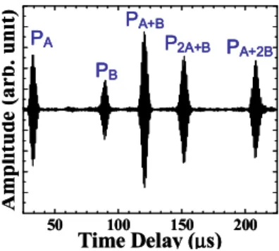
For PAW experiments a 111µm-thick BIT/PZT composite film [14,15] was deposited on a 0.702mm-thick SS plate as shown in Fig.10. Then two IDT electrodes were made on top of the film by the colloidal silver spray using the IDT mask shown in Fig.7. Their thickness was about several microns. Fig.11 shows the measured PAW signals in time domain using the integrated PAW transducer shown in Fig.10 near edge “A” operated in the pulse-echo mode at 150°C. The pass band of the band pass filter was also between 0.5MHz and 2.0MHz. In Fig.11 PA, PB , PA+B, P2A+B and PA+2B are the
reflected echoes either from the edge “A” or the edge “B” through the corresponding PAW travel paths (distance) of 2A, 2B, 2(A+B), 2(2A+B) and 2(A+2B), respectively. The longest travel distance in this figure was 594mm (for PA+2B). The
echoes of PA and PB are weaker than PA+B because they travel
uni-directionally along A or B direction, respectively, but echo PA+B travel both along “A” and “B” direction and
summed at the generating and receiving IDT near the edge “A”. Along longer propagation distance echo strength will be weaker due to higher loss in the path. However, the echoes in Fig. 11 show good SNRs. The two edges can be considered as large deep defects (cracks) in practical NDT applications. It means that this integrated PAW transducer can be regarded as excellent NDT tool at 150°C for a sensing distance of 594mm (e.g. PA+2B).
When both IDTs shown in Fig.10; one as the PAW transmitter and another as the receiver, are used, the measured PAW signal, P, in time domain and in transmission mode is shown in Fig.12. The IDT near edge “B” can be also individually operated in the pulse-echo mode. BIT/PZT films were shown to be able to sustain operation temperature more than 440°C [14,15].
IDT IDT
Stainless Steel Plate (0.702 mm Thick) 47 mm 90 mm 35 mm 34 mm Electrical Probe 172 mm Edge A Edge B 125 mm IDT IDT
Stainless Steel Plate (0.702 mm Thick) 47 mm 90 mm 35 mm 34 mm Electrical Probe 172 mm Edge A Edge B 125 mm
Fig.10 A 0.702mm thick steel plate with a PAW transducer with an IDT operated in pulse-echo mode. The 111µm piezoelectric film was made of a BIT/PZT composite. 50 100 150 200 A mp lit u d e (ar b . u n it ) Time Delay (µs) PA PB PA+B P2A+B PA+2B 50 100 150 200 A mp lit u d e (ar b . u n it ) Time Delay (µs) PA PB PA+B P2A+B PA+2B
Fig.11 Ultrasonic performance of PAW transducer shown in Fig. 10 with an IDT operated in pulse-echo mode at 150°C in time domain. The SS substrate is 0.702mm thick. P 20 30 40 50 A m plitude (a r b . unit) Time Delay (µs)
Fig.12 Ultrasonic performance of PAW transducers shown in Fig.10 with IDT operated in transmission mode at 150°C in time domain.
0 1000 2000 3000 4000 5000 0 1000 2000 3000 4000 5000
V
e
lo
c
ity
(m
/s
)
fh (Hz.m)
S0 S0 a0 a0 VR=2919m/s phase velocity group velocity 0 1000 2000 3000 4000 5000 0 1000 2000 3000 4000 5000V
e
lo
c
ity
(m
/s
)
fh (Hz.m)
S0 S0 a0 a0 VR=2919m/s phase velocity group velocityFig. 13 The calculated PAW and SAW (Rayleigh wave) dispersion curve for the 0.702mm thick SS plate shown in Fig.10.
At room temperature the measured PAW group velocity of the device shown in Fig.10 is 2936m/s. The measured Vl
and Vs of the SS plate at room temperature are 5828m/s and
3151m/s, respectively. The calculated PAW phase V (in solid lines) and group velocities Vg (in dashed lines), and RAW
velocity VR (2919 m/s) are shown in Fig.13. It is found that at
the plate thickness h = 0.702mm and f = 1MHz the theoretically calculated Vg for the first anti-symmetric mode a0
is 3030m/s. The measured Vg was 2936m/s which agrees well
with the calculated value of 3030m/s. Note that the calculated result does not include the effect of the BIT/PZT composite film loading. Therefore the PAW shown in Fig.11 is the first anti-symmetrical plate wave mode a0. Because the BIT/PZT
composite film has slower L wave velocity, 2450 m/s, than that, 5828 m/s, of SS plate, its 111µm thickness will slow
down the PAW in the plate region coated with this composite film [27,30,31].
The geometry of the PAW transducer, such as thickness of the BIT/PZT film and finger widths of the IDT which affect operating frequency will be investigate in order to excite PAW waves efficiently. By comparing the measurement data in Fig.11 with those at room temperature it is found that the signal strength was 2dB weaker at 150°C. The measured PAW (a0) at 150°C was 2860m/s.
V. FLEXIBLE ULTRASONIC TRANSDUCERS
For NDT of objects having curved surfaces flexible UTs are more suitable than classical UTs with flat probing ends. This capability insures the self-alignment of the UTs to the curved and complex geometry so that the transmitted ultrasonic energy can be maximized for improved diagnoses. Thus, the research interest here is to develop flexible UTs for potential implementation at room temperature and HT applications on samples of simple and complex geometries. In commercially available flexible transducers, piezoelectric polymers such as polyvinylidene fluoride (PVDF) [32,33] and piezoelectric ceramic/polymer composites [34-36] are mainly used as piezoelectric materials. Both materials include polymer which prevents the use of such flexible transducers at elevated temperature. For instance, PVDF shows significant piezoelectric deterioration above 65°C. Several copolymers have superior temperature stability compared to PVDF, however, operation temperature is limited to around 90-100°C [32]. In addition, piezoelectric polymers have low electromechanical coupling coefficients [33,37]. Compared to bulk piezoelectric ceramics or polymers, piezoelectric ceramic/polymer composites may have superior electromechanical coupling properties in addition to flexibility and low dielectric losses. However, at HT good ultrasonic performances were reported only up to 80°C in particular under thermal cycling environment [38] due to the soft state of the resin as it reaches its glass transition temperature of 150°C. Other flexible HTUTs have been also reported [39]. Because of single crystal films used, to provide the flexibility, the thickness of the piezoelectric film ranged from 0.2 to 10µm. These films provide an operating frequency normally higher than 30 MHz that may not be suitable for NDT of thick and highly attenuating materials.
A. Flexible UT using SS foil as substrates
Since SS substrate can sustain operation temperature more than several hundred degrees Celsius (> 700°C), it may be brazed or welded onto metallic structures for HT operation. It may be also glued onto metallic, polymer or graphite/epoxy composite materials for NDT applications. The techniques described in Section II were used to fabricate the PZT/PZT composite films. The top electrodes were made by silver paste. Fig.14 illustrates two views of a PZT/PZT 120µm thick composite film five UTs array directly fabricated onto a 75µm thick SS foil with this particular merit. Thinner SS foils may also be used as reported in [40]. The entire transducer array
structure was sandwiched by polyimide films excluding the probing side of the membrane (the side opposite to thick piezoelectric film) so that it may be protected from the moisture in the environment and can operate at temperatures up to 150°C which is currently limited by the operating temperature of PZT/PZT composite. Copper strips were used for electrical connections.
UT 1 UT 2 UT 3 UT 4 UT 5 (a) (b)
Fig.14 A flexible PZT/PZT 120µm thick composite film five UT array using a 75µm thick SS membrane. 4 8 12 16 20 24 28 32 36 40 44 A m pl it u d e ( a rb. un it ) Time Delay (µs) L2 L4 L6 4 8 12 16 20 24 28 32 36 40 44 A m pl it u d e ( a rb. un it ) Time Delay (µs) L2 L4 L6 (a) 0 5 10 A m pl it ude ( a r b. un it ) Frequency (MHz) L2 0 5 10 A m pl it ude ( a r b. un it ) Frequency (MHz) L2 (b)
Fig.15 Ultrasonic performance of the flexible ultrasonic transducer (UT3) in (a) time and (b) frequency domains for NDT of a 13.8mm thick steel plate at 150°C.
When this flexible UT array was pressed onto a steel plate of 13.8mm together with HT coupling oil and fixed by a mechanical clamp, the measured ultrasonic response of UT3, shown in Fig.15, in time and frequency domains at 150°C, is obtained and presented in Fig.15. L2, L4 and L6 represent the
first, second and third round trip echo through thickness of the steel plate. The center frequency, 6dB bandwidth and SNR of the L2 echo are determined to be 2.6MHz, 2.6MHz and 22dB,
respectively. We have also used steel, titanium, nickel and copper membranes for the fabrication of flexible UTs [15]. This type of flexible UTs has been also employed to inspect metallic tubes, graphite/epoxy composite and polymer materials [40].
B. Flexible UT using polyimide as substrates
In order to increase the flexibility of the flexible UT polyimide films are used for this investigation because polyimide films can sustain 350°C and the sol-gel PZT/PZT multilayer fabrication process. Its acoustic impedance is also different than that of the SS substrate. Because the polyimide film is an insulator, a colloidal silver spray and nickel alloy electroless plating methods were developed to coat a conductive layer onto the piezoelectric composite film side of the film as the bottom electrode before the coating of the piezoelectric composite thick films. However, in this
1124 2006 IEEE Ultrasonics Symposium
particular sample, colloidal silver spray method was used and two microns thick silver paint was deposited between the top polyimide film and the PZT/PZT composite. Care has been taken to strengthen the adhesion between this electrode layer and the polyimide. Fig.16 shows the flexible UT with the 60µm polyimide film substrate with a 60µm thick PZT/PZT composite film. This PZT/PZT film thickness is obtained using ten layers of coating process. Such fabrication process implies that the polyimide film has sustained ten thermal cycles during the drying and firing of the PZT/PZT composite film and also the corona poling heating process. As shown in Fig.16, the current process produces less than perfect flat UT surfaces (presence of wrinkles) due to the applied processing heat. Efforts are being devoted to reduce or eliminate such wrinkles and imperfections.
Fig.16 A flexible UT using polyimide film as the substrate.
10 20 30 A m pl it u d e ( a rb . un it ) Time Delay (µs) L2 L4 L6 10 20 30 A m pl it u d e ( a rb . un it ) Time Delay (µs) L2 L4 L6 (a) 0 10 20 30 A m pl it ude ( a rb. uni t) Frequency (MHz) L2 0 10 20 30 A m pl it ude ( a rb. uni t) Frequency (MHz) L2 (b)
Fig.17 Room temperature flexible UT response in (a) time and (b) frequency domain for a 25.2mm thick Al plate.
10 20 30 A m pl it ude ( a rb. uni t) Time Delay (µs) L2 L4 L6 10 20 30 A m pl it ude ( a rb. uni t) Time Delay (µs) L2 L4 L6 150°C (a) 0 10 20 30 Am pl it ud e ( a rb . un it ) Frequency (MHz)
L
2 0 10 20 30 Am pl it ud e ( a rb . un it ) Frequency (MHz)L
2 150°C (b)Fig.18 HT (150oC) flexible UT response in (a) time and (b) frequency domain
for a 25.2mm thick Al plate.
In order to demonstrate the performance of the flexible UT using polyimide film as the substrate at elevated temperature, the transducer was pressed onto an Al plate heated to 150°C.
HT oil couplant was placed between the probing side of the polyimide film and Al plate. Figs.17(a) and (b) show the transducer response, in time and frequency domains respectively, in pulse-echo mode at room temperature. L2 and
L4 are the first and second round trip echoes through the
thickness of the Al plate. The center frequency, the 6dB band width and SNR of the L2 echo are determined to be 15.4MHz,
10.8MHz and 25dB, respectively. The ultrasonic response of the transducer at 150°C is shown in Fig.18. The center frequency, the 6dB bandwidth and SNR of the L2 echo at this
operating temperature is 13.4MHz, 6.7MHz and 20dB, respectively. It is observed that the signal strength of the L2
echo is decreased by about 3dB and the frequency bandwidth reduced by 4.1MHz. At 150oC, the time delay of the L2 echo
travelling in Al substrate has 0.2µs more delay than that measured at room temperature.
VI. CONCLUSIONS
Thick (>40µm) ceramic films as piezoelectric UTs were successfully deposited on metallic and non-metallic substrates by a spray technique. In the film fabrication a composite consisting of piezoelectric BIT or PZT powders well mixed with PZT solution was directly sprayed onto different substrates. It is then dried, fired or annealed by heat. Multiple coating is used to achieve preferred thicknesses. A corona poling is used to achieve the piezoelectricity of the film. The top electrode is accomplished by a painting method with silver paste, platinum paste or silver paint. All fabrication processes can be carried out on-site and by handheld devices. Integrated ultrasonic longitudinal, shear, surface and plate wave transducers have been made. The same technology was also used to fabricate flexible transducers consisting of a thin substrate, a piezoelectric ceramic film and electrodes.
Integrated ultrasonic S wave probes were fabricated onto steel substrates with the use of mode conversion from L to S waves. The theoretical calculation indicates that the maximum energy conversion rate from the L to S wave is 97.5% at the L wave incident angle θ = 67.2° as shown in Fig. 2, and the reduction of the energy conversion rate is within 1% in the θ range between 60.8° and 72.9°. Let the L UT be made in a plane parallel to the propagation direction of the mode converted S waves as shown in Fig. 3 and the θ be 61.5°, clean S waves were generated. The reduction of energy conversion rate at θ equal to 61.5° is only 0.8% smaller than the maximum conversion rate at θ = 67.2°. A probe that can simultaneously generate and receive both L and S waves was also demonstrated. All the above mentioned probes have been made and operated up to 350 °C with a center frequency of 5– 7 MHz, 6dB bandwidth of 4–6 MHz, and SNR of more than 20 dB.
The fabrication and ultrasonic performance of integrated RAW and PAW transducers directly onto Al alloy and SS substrates for NDT applications at 150°C have been demonstrated. The IDT mask was made by an EDM method.
A colloidal silver spray method was used to form the IDT electrodes at room temperature through the IDT mask. Experimental results show RAW propagation along a 25mm thick Al alloy substrate and PAW propagation in the first anti-symmetrical mode along a 0.702mm thick SS plate. The pass band of the filters for RAW or PAW is between 0.5MHz and 2.0MHz. The measured RAW and PAW results agree well with the theoretically calculated values. If the edges of the substrates can be considered as large defects or cracks, measured signals with good signal to noise ratio demonstrated the NDT capability in a distance of several centimeters or tens of centimeters of these integrated RAW or PAW transducers operated at 150°C. If the substrate is thick, both SAW and bulk L wave can be generated and detected simultaneously for NDT applications along the surface or thickness direction, respectively of the substrate. Arrays of these transducers can be readily achieved as well.
Flexible UTs consisting of a 75µm thick SS foil or a 60µm thick polyimide film, a piezoelectric PZT/PZT composite film and electrodes were developed. The flexibility was realized owing to the porosity of piezoelectric film and the thinness of substrate and electrodes. PZT/PZT composite was chosen as piezoelectric film because of its high piezoelectric strength. Thicknesses of 40 to 120µm were obtained by the sol-gel spray technique. Electrode materials are silver paste, platinum paste or sprayed silver paint. SS foil itself serves as the bottom electrode; however, polyimide film required a coating of a conducting layer before the deposition of PZT/PZT composite film. The UT array can be conveniently configured by making several top electrodes. The flexible UT array with the SS foil has been successfully tested at 150°C for NDT of a 13.8mm thick steel. The flexible UT with the polyimide film was also used for NDT of a 25.2mm thick Al plate at room temperature and 150°C. Such flexible UTs are expected to be applicable for health monitoring of humans and structures with complex shapes and geometries.
ACKNOWLEDGMENT
Authors would like to thank Y. Ono, J.-F. Moisan, H. Hebert, K.-T. Wu, Q. Liu, L. Song, J. Tatibouet and N. Mrad for their technical assistance. Financial support from Natural Sciences and Engineering Research Council of Canada is acknowledged.
REFERENCES
[1] J. Krautkrämer and H. Krautkrämer, “Ultrasonic Testing of Materials”, Springer-Verlag, Berlin, 1990.
[2] A.S. Birks, R.E. Green, Jr. and P. McIntire, ed., “Nondestructive Testing Handbook”, 2nd Ed., vol.7: Ultrasonic Testing, ASNT, 1991.
[3] M.V. Gandhi and B.S. Thompson, Smart Materials and Structures, London; New York, Chapman & Hall, 1992.
[4] J.-B. Ihn and F.-K. Chang, “Ultrasonic Non-destructive Evaluation for Structure Health Monitoring: Built-in Diagnostics for Hot-spot Monitoring in Metallic and Composite Structures”, Chapter 9 in Ultrasonic Nondestructive Evaluation Engineering and Biological
Material Characterization, edited by T. Kundu, CRC Press, New York, 2004.
[5] L.C. Lynnworth, Ultrasonic Measurements for Process Control, New York: Academic Press, 1989.
[6] Kundu, T. Ed, Ultrasonic Nondestructive Evaluation: Engineering and Biological Material Characterization, CRC Press, N.Y., 2004.
[7] B. Butler, S. B. Palmer, and G. J. Primavesi, “Techniques for the generation of ultrasound for extended periods at high temperatures,”
Ultrasonics, vol.17, pp.249-254, 1979.
[8] J. R. Fothergill, P. Willis, and S. Waywell, “Development of high-temperature ultrasonic transducers for under-sodium viewing applications,” British Journal of NDT, vol.31, pp.259-264, 1989. [9] N. D. Patel, S. X. Fulford, and P. S. Nicholson, “High frequency-high
temperature ultrasonic transducers,” Review of Progress in QNDE, vol.9, pp.823-828, 1990.
[10] T. Arakawa, K. Yoshikawa, S. Chiba, K. Muto, and Y. Atsuta, “Applications of brazed-type ultrasonic probes for high and low temperatures uses,” Nondestr. Test. Eval., vol.7, pp.263-272, 1992. [11] T. N. Nguyen, M. Lethiecq, B. Karlsson, and F. Patat, “Development of
a broad-band ultrasonic transducer for high temperature applications,”
Acta Acustica, vol.3, pp.331-338, 1995.
[12] H. Mrasek, D. Gohlke, K. Matthies, and E. Neumann, “High temperature ultrasonic transducers,” NDTnet, vol.1, no. 9, 1996. [13] H. Karasawa, M. Izumi, T. Suzuki, S. Nagai, M. Tamura, and S.
Fujimori, “Development of under-sodium three-dimensional visual inspection technique using matrix-arrayed ultrasonic transducer,” J. of Nuclear Science and Technology, vol.37, pp.769-779, 2000.
[14] M. Kobayashi and C.-K. Jen, “Piezoelectric thick bismuth titanate/PZT composite film transducers for smart NDE of metals”, Smart Materials and Struct., vol.13, pp.951-6, 2004.
[15] M. Kobayashi, C.-K. Jen, Y. Ono and J.-F. Moisan, “Integrated high temperature ultrasonic transducers for NDT of metals and industrial process monitoring”, CINDE , vol.26, pp.5-10, March/April 2005. [16] H. Adachi, Y. Kuroda, T. Imahashi, and K. Yanagisawa, “Preparation
of piezoelectric thick films using a jet printing system”, Jpn. J. Appl. Phys., vol.36, pp.1159-1163, 1997.
[17] X. Zhao, J.R.G. Evans, and M. J. Edrisinghe, “Direct ink-jet printing of vertical walls”, J. Am. Ceram. Soc., vol.85, pp.2113-2115, 2002. [18] R.A. Dorey, R.W. Whatmore, S.P. Beeby, R.N. Torah and N.M. White,
“Screen printed PZT thick films using composite film technology”, Integrated Ferroelectrics, vol.54, pp.651-658, 2003.
[19] P. Marechal, F. Levassort, J. Holc, L.-P. Tran-Huu-Hue, M. Kosec and M. Lethiecq, “High-frequency transducers based on integrated piezoelectric films for medical imaging”, IEEE Trans. UFFC, vol.53, pp.1524-33, 2006.
[20] C. Galassi, E. Roncari, C. Capiani, P. Pinasco “PZT-based suspensions for tape casting”, J. Eur. Ceram. Soc., vol.17, pp.367-71, 1997. [21] F. Levassort, T. Bove, E. Ringgaard, L.P. Tran-Huu-Hue, J. Hole and
M. Lethiecq, “A complete reange of tape-cast piezoelectric thick films for high frequency ultrasonic transducers”, Proc. IEEE Ultrason. Symp., pp.2003-6, 2003.
[22] K.L. Gentry, J.M. Zara, S.-D. Bu, C.-B. Eom and S.W. Smith, “Thick film sol gel PZT transducer using dip coating”, Proc. IEEE Ultrasonics Symp., vol.2, pp.977-980, 2000.
[23] X.-Y. He, A.-L. Ding, X.-S. Zheng, P.-S. Qiu and W.-G. Luo, “Preparation of PZT(53/47) thick films deposited by a dip-coating process”, Microelectronic Eng., vol.66, pp.865-871, 2003.
[24] M. Shimomura, T. Tsurumi, Y. Ohba and M. Daimon, “Preparation of lead zirconate titanate thin film by hydrothermal method”, Jpn. J. Appl. Phys., vol.30, pp.2174-2177, 1991.
[25] N. Katsura, M. Ishikawa, T. Sato, M. Takeuchi, N. Kawashima, M. Kurosawa and S. Takeuchi, “Development of water immerse type ultrasound probe with PZT film deposited by hydrothermal method”, Proc. IEEE Ultrasonics Symp., pp.1300-5, 2003.
[26] D. A. Barrow, T. E. Petroff, R. P. Tandon and M. Sayer, “Characterization of thick lead zirconate titanate films fabricated using a new sol gel based process”, J. Appl. Phys. vol. 81, pp.876-881, 1997
1126 2006 IEEE Ultrasonics Symposium
[27] B.A. Auld, Acoustic fields and waves in solids, vol.2, John Wiley & Sons, New York, 1973, pp.30-38.
[28] M.O. Si-Chaib, H. Djelouah, and M. Bocquet, “Applications of ultrasonic reflection mode conversion transducers in NDT”, NDT&E Int’l, vol.33, pp.91-99, 2000.
[29] W.G. Mayer, “Energy partition of ultrasonic waves at flat boundaries” Ultrasonics, vol.3, pp.62-69, 1965
[30] I.A. Viktorov, Rayleigh and Lamb waves, Plenum, New York, 1967. [31] E.L. Adler, J.K. Slaboszewicz, G.W. Farnell, and C.-K. Jen, “PC
software for SAW propagation in anisotropic multilayers”, IEEE Trans. UFFC, vol.37, pp.215-223, 1990.
[32] L. F. Brown and A. M. Fowler, “High vinylidene-fluoride content P(VDF-TrFE) films for ultrasound transducers”, Proc. IEEE Ultrason. Symp., pp.607-609, 1998.
[33] J.-M. Park, J.-W. Kong, D.-S. Kim, and D.-J. Yoon, “Nondestructive damage detection and interfacial evaluation of single-fibers/epoxy composites using PZT, PVDF and P(VDF-TrFE) copolymer sensors”,
Composites Science and Technology, vol.65, pp.241-256, 2005. [34] T. F. McNulty, V. F. Janas, A. Safari, R. L. Loh and R. B. Cass, “Novel
processing of 1-3 piezoelectric ceramic/polymer composites for transducer applications”, J. Am. Ceram. Soc., vol.78, pp.2913-2916, 1995.
[35] H. Karasawa, M. Izumi, T. Suzuki, S. Nagai, M. Tamura, and S. Fujimori, “Development of under-sodium three-dimensional visual inspection technique using matrix-arrayed ultrasonic transducer”, J. of Nuclear Science and Technology, vol. 37, pp.769-779, 2000.
[36] L. J. Bowen, R. L. Gentilman, H. T. Pham, D. F. Fiore, and K. W. French, “Injection molded fine-scale piezoelectric composite transducers”, Proc. IEEE Ultrason. Symp., pp.499-503, 1993.
[37] A. Gachagan, P. Reynolds, G. Hayward, and A. Mcnab, “Construction and evaluation of a new generation of flexible ultrasonic transducers”,
Proc. IEEE Ultrason. Symp., pp.853-856, 1996.
[38] C. Devallencourt, S. Michau, C. Bantignies, and N. Felix, “A 5 MHz piezocomposite ultrasound array for operations in high temperature and harsh environment”, Proc. IEEE Ultrason. Symp., pp.1294-1297, 2004. [39] M. Akiyama, T. Kamohara, K. Nishikubo, N. Ueno, H. Nagai, and T.
Okutani, “Ultrahigh temperature vibration sensors using aluminum nitride thin films and W/Ru multilayer electrodes”, Appl. Phys. Lett., vol.86, 022106 (3 pages), 2005.
[40] M. Kobayashi, C.-K. Jen, and D. Lévesque, “Flexible ultrasonic transducers,” IEEE Trans. UFFC, vol.53, pp.1478-1486, 2006.