Publisher’s version / Version de l'éditeur:
Vous avez des questions? Nous pouvons vous aider. Pour communiquer directement avec un auteur, consultez la première page de la revue dans laquelle son article a été publié afin de trouver ses coordonnées. Si vous n’arrivez pas à les repérer, communiquez avec nous à [email protected]. Questions? Contact the NRC Publications Archive team at
[email protected]. If you wish to email the authors directly, please see the first page of the publication for their contact information.
https://publications-cnrc.canada.ca/fra/droits
L’accès à ce site Web et l’utilisation de son contenu sont assujettis aux conditions présentées dans le site LISEZ CES CONDITIONS ATTENTIVEMENT AVANT D’UTILISER CE SITE WEB.
Proceedings of the IEEE InternationalWorkshop on Haptic Audio Environments
and their Applications (HAVE'2005), 2005
READ THESE TERMS AND CONDITIONS CAREFULLY BEFORE USING THIS WEBSITE. https://nrc-publications.canada.ca/eng/copyright
NRC Publications Archive Record / Notice des Archives des publications du CNRC : https://nrc-publications.canada.ca/eng/view/object/?id=f97640d0-7c71-430b-88a0-3485d719c21b https://publications-cnrc.canada.ca/fra/voir/objet/?id=f97640d0-7c71-430b-88a0-3485d719c21b
NRC Publications Archive
Archives des publications du CNRC
This publication could be one of several versions: author’s original, accepted manuscript or the publisher’s version. / La version de cette publication peut être l’une des suivantes : la version prépublication de l’auteur, la version acceptée du manuscrit ou la version de l’éditeur.
Access and use of this website and the material on it are subject to the Terms and Conditions set forth at
On-Screen Laser Spot Detection for Large Display Interaction
Lapointe, Jean-François; Godin, Guy
National Research Council Canada Institute for Information Technology Conseil national de recherches Canada Institut de technologie de l'information
On-Screen Laser Spot Detection for Large
Display Interaction*
Lapointe, J.-F., and Godin, G.
October 2005
* published in the Proceedings of HAVE'2005 - IEEE International Workshop on Haptic Audio Environments and their Applications. Ottawa, Ontario, Canada. pp.72-76. October 1-2, 2005. NRC 48283.
Copyright 2005 by
National Research Council of Canada
Permission is granted to quote short excerpts and to reproduce figures and tables from this report, provided that the source of such material is fully acknowledged.
HAVE 2005 – IEEE International Workshop on
Haptic Audio Visual Environments and their Applications Ottawa, Ontario, Canada, 1-2 October 2005
0-7803-9377-5/05/$20.00 ©2005 IEEE
On-Screen Laser Spot Detection for Large Display Interaction
Jean-François Lapointe and Guy Godin
Institute for Information Technology National Research Council of Canada [Jean-Francois.Lapointe,Guy.Godin]@nrc-cnrc.gc.ca
Abstract
Laser pointer based interfaces present an interesting alternative for interaction with large displays such as those provided by video projection systems. In order to operate correctly, such systems need to quickly and reliably detect the on-screen laser spot generated by the pointer. This paper describes a fast algorithm for real-time laser spot tracking and presents some performance results.
Keywords: Human-computer interaction, laser pointer, system performance, computer vision.
1. Introduction
Large displays are increasingly present for everyday use, at work or at home. Interacting with these displays requires different form of control than for a classical desktop computer, since both keyboard and mouse require a horizontal surface to work.
The alternatives for interaction are therefore: touch sensitive panel, light/electronic pens, laser pointers or some other kind of wireless handheld input devices (WHID), as well as speech and gesture recognition systems.
Video projectors are quickly growing in popularity, given their increasing affordability, ease-of-use and flexibility (portable, adjustable to different projection sizes or surfaces, etc.). In fact they can accommodate diverse situations and can be used in either front or rear-projection systems, depending on the situation and available space.
A lot of research is currently focusing on interaction with video projection systems. Given the low reliability of most current gesture and speech recognition systems and the relatively high price of large touch displays, the interaction choice is basically limited to the use of laser pointers and other WHID, namely those with inertial systems such as the GyroPoint, as well as those with thumb actuated trackballs or isometric joysticks.
Several studies have shown the low performance of handheld devices and it can easily be observed that those are used mainly for tasks involving infrequent interactions such as slide show presentation or projector configuration.
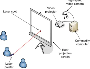
Laser pointer interfaces, on the other hand, offer an interesting alternative for close interaction with large displays such as those provided by video projection systems (Figure 1). This is due to their naturalness of use, which is well suited for direct manipulation interaction in collaborative environments. In fact, a literature review reveals several publications on this topic since 1998 [1-15].
Video projector Commodity computer Laser spot Rear projection screen Laser pointer High-speed video camera
Figure 1. Laser pointer interface (rear projection case)
The operation of laser pointer interfaces can be divided in three phases [8]:
1) laser spot detection 2) camera-to-display mapping
3) use of appropriate interaction technique
Furthermore, the system performance of those interfaces can be characterized by three criteria: reliability, latency and accuracy.
Reliability refers to the proportion of frames where the laser
spot is present on the display and detected correctly.
Latency refers to the time elapsed between a laser input and
the corresponding action on the display (in our case, a mouse cursor move).
Accuracy refers to the distance, measured in pixels,
between the laser spot location on the display and the corresponding display coordinates computed by the system.
Previous publications reported with varying levels of detail the processing steps required to build laser pointer interfaces [2, 8, 10, 14, 12]. None of them however provided much detail about the laser spot detection method used.
This information however is critical, since the usefulness of a laser pointing interface depends on its reliable real-time performance. The processing bottleneck here is directly related to the image processing involved in the detection of the on-screen laser spot, since it must be repeated at a high frequency. For comparison, modern computers track mouse position at sample rates of 40 to 125 Hz. The sample rate is important due to the fact that it defines the theoretical lower limit of an input device’s latency, since the latency (in second) cannot be shorter than the inverse of the sample rate.
This paper presents a fast laser spot detection method that can be used for real-time laser pointer interaction on a commodity computer. Before that, we give an overview of the pre-processing steps used by our system to allow the correct operation of the laser pointing interface.
2. Overview of the pre-processing steps
In order to operate the laser pointer interface correctly, our system needs to previously determine the camera-to-display mapping and configure the cameras for use in the operating lighting conditions.
2.1 Camera-to-display mapping
We currently use a homography-based method to determine the camera-to-display mapping. This basically works by projecting an image with four recognizable patterns on the display, with predetermined locations.
A standard equation solving method is then used to compute the homography that will be used for the mapping. For more details about the method, please refer to [12].
Since this step requires the camera to detect the patterns on the display, it is important to have a good contrast between the display and the environment. Therefore, this step is preferably done in low lighting conditions, where the camera is first configured to avoid saturation, by projecting a fully white display and adjusting the gain and exposure time using an iterative method.
2.2 Camera configuration
In order to work properly during its operation, the laser pointer interface requires that the camera detect a contrast between the on-screen laser spot and the rest of the environment. As explained in the next section, this is achieved through the use of a thresholding method.
In order to use this method, the camera needs to avoid saturation when looking at the environment, when there is no laser spot. Therefore, it is necessary to adjust its gain and exposure time, using the same method as for the camera-to-display mapping, but now with the lighting conditions expected for the operation.
3. Laser Spot Detection Method
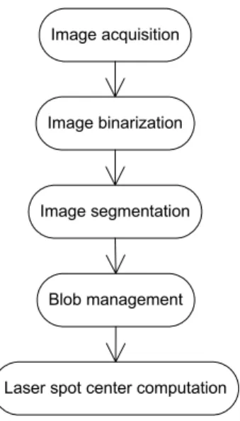
The laser spot detection method can be divided in 5 steps that are illustrated in Figure 2 below.
Image acquisition
Image binarization
Image segmentation
Blob management
Laser spot center computation
Figure 2. Laser spot detection steps
3.1 Image acquisition
The light intensity of each pixel of the image recorded by the camera is measured on a discrete level. Here a standard 8 bit resolution was used in order to provide intensity measures ranging from 0 to 255.
3.2 Image binarization
In order to speed up processing, intensity images are binarized using a thresholding algorithm, therefore resulting with an image with pixels having a value of zero or one.
The threshold value is predetermined during the camera configuration step (section 2.2) by measuring the maximum intensity value for all the pixels in the expected operating conditions, without interference from the laser pointer. The threshold is set above this maximum intensity value by a margin that is adjusted to be close enough to help laser spot detection without hampering the binarization process due to variations in light measurements by the camera that could be related to noise or reflections on the display.
3.3 Image segmentation
The binarized image is then analyzed with the help of a pattern recognition algorithm for blob detection. Here, we used a classic single-pass method based on component labeling [17, 18].
The detected blobs, if any, are numbered and stored along with their area (in pixels) as well as with the sum of their pixel camera coordinates along the X (horizontal) and Y (vertical) axes of the camera image.
3.4 Blob management
The blobs found in the previous steps are then managed in the following way:
• If no blob is detected, we conclude that no laser spot was found in the image and then return an error code.
• If only one small blob is detected, we proceed directly to the next step, i.e. laser spot center computation.
• If several blobs are detected, a decision is made depending on their number and their spread on the image:
o If there are only a few blobs and they are localized within a predetermined distance (measured in pixels), the system groups them to form a single blob.
This condition can be explained by the fact that a fast on-screen laser spot movement can be recorded as a trace on the camera image, since the exposure time is not infinitely small but rather discrete with a duration of a few ms. Again, due to some digitization artifacts resulting from the image acquisition and/or binarization steps, this can cause the detection of a localized group of blobs.
o If there are too many blobs or if they are spread all across the image or if they cover a total area that is too large, the system returns an error code, since this indicates a problem that can be related to different causes, such as a bad image binarization or the use of more than one laser pointer.
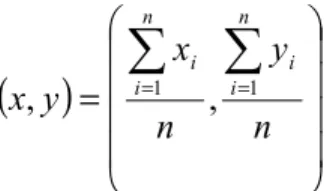
3.5 Laser spot center computation
Finally, when a single blob is reported by the previous step, the coordinates (x, y) of its center are computed by using the following equation:
(
)
=
∑
∑
= =n
y
n
x
y
x
n i i n i i 1 1,
,
where n represents the number of pixels in the blob (its area) and where (xi, yi) are the coordinates of each
individual pixel.
In order to increase the accuracy of the system, the computed center coordinates are stored as floating point values.
4. Implementation
The system used is quite flexible, allowing for a large range of display size and resolution, as well as multiple configurations of the camera-display set.
In order to be compatible with different laser pointers, the system uses information based on the light intensity of the laser spot to detect it on camera images.
The system evaluated here was composed of a 60 fps grayscale video camera with a resolution of 640×480 pixels, an XGA (1024×768 pixels) video projector and a 1.2 m (diagonal size) front projection screen (Figure 3). Both the camera and the projector were connected to a Pentium 4 single processor computer running at 2.2 GHz. When running, the application used a maximum of 27 % of the CPU resources and 3 MB of memory.
Figure 3. The laser pointer interface
It is important to note that the system can be used both with front and rear projection systems.
Rear projection is often preferred, since users can stand directly in front of the screen without occluding the camera or the projector. Rear projection can also possibly offer a better contrast, since rear projection screens generally transmit more light than they reflect, resulting in a better contrast between the laser spot and the display, since the laser spot is directed toward the camera, while the projector is oriented toward the user.
On the other hand, front projection systems need less space to operate, given that the projector is located in front of the screen. They can also project directly on a white wall or sheet, therefore making them less costly, since no special projection screen is needed.
The system was tested with two laser pointer wavelengths: 680 nm (red) and 820 nm (infrared). These two conditions were judged important, since the choice of using either a visible (red) or invisible (infrared) laser pointer can be advantageous depending of the context of use. For example, it has been reported that the use of a visible laser increases the pointing performance, while the use of an invisible laser makes the system appear more fluid to the user. This latter effect is caused by the masking of the discrepancies between the laser spot and the mouse cursor, which are related to system inaccuracy and latency [1].
Moreover, the use of a visible laser is not suited for stereoscopic displays, since in the general case, the spot will appear to be positioned at screen depth, which will generally differ from the apparent depth of the underlying scene (or be perceived as a double spot by users) [12]. In that case, an infrared laser pointer can be used as reported before [13].
All the auto-adjustments of the camera were turned off and the camera was aligned so that its optical axis was roughly perpendicular to the display screen. Also, the pre-processing steps described in section 2 were followed.
Finally, the system was evaluated in an artificially lit room representative of a regular office lighting conditions with no direct sunlight and an ambient lighting level of 500 luxs.
4.1. Assumptions
The system can work as long as the three following conditions are fulfilled:
• The display screen is entirely visible (and in focus) inside the field of view of the camera
• There is no relative movement between the screen and the camera once the system is started
• The laser spot is brighter than anything else in the field of view of the camera
5. Performance results
As described before, the criteria used to evaluate the performance of the system are: reliability, accuracy and latency.
The performance results obtained are summarized in Table 1 below and were the same when using either the red or the infrared laser pointer:
Table 1. Performance results
Criteria Result Reliability 100 %
Accuracy 3 screen pixels (worst case) Latency 44/64/56 ms (min/max/average)
5.1. Reliability
With a reliability of 100 %, meaning that the laser spot was detected in every frame, the system showed a perfect reliability.
5.2. Accuracy
Accuracy was measured by pointing at different regions of the screen and recording the maximum difference in pixel from the tip of the on-screen cursor to the stationary laser spot. The measured accuracy was of 3 screen pixels in the worst cases, a result similar to what has been reported before [8, 12].
The main factor that can explain this result is related to the camera-to-display mapping method used. In fact, the analysis of the accuracy of the system revealed that the accuracy varies from one region of the display to another, with a 3 pixel discrepancy in the worst case. The accuracy was however better than that in the four regions where features of the pattern were projected to compute the mapping (see section 2.1). In fact, in those regions of the display, the accuracy approached 1 pixel. The analysis of the accuracy also revealed that inaccuracies tend to shift towards the center and the display sides, therefore revealing that radial distortion in the camera lens could explain the problem.
5.3. Latency
To measure latency, the cursor was placed at an arbitrary position in the computer screen. The pointer was then activated to point at an arbitrary region within the screen area. The scene was recorded by a 250 fps high speed video camera. The time taken by the cursor to reach the static laser spot was then measured from the resulting video by counting the number of frames between the two events. In order to characterize the variations in latencies, several measures were taken, as reported in Table 1.
Due to computation and communication times, the measured latencies are slightly superior to the theoretical lower limit of 16.6 ms computed by inverting the image acquisition rate of 60 Hz. In all cases however, the latency is well under the limit of 80 ms which has been shown to hamper user performance in tracking tasks with position control [16]. When using a visible laser however, the lag of the mouse cursor is detectable during fast laser movements.
6. Discussion & Future Work
This paper presented and evaluated for the first time a fast and reliable laser spot detection method for use with laser pointer interfaces. This method allows the reliable and real-time operation of a laser pointer interface at an update rate of 60 Hz with the use of a commodity computer.
Given the performance results obtained, further research is necessary, especially to improve the accuracy of the system. Also, the use of a faster camera could reduce the latency of the system therefore reducing the lag impression related by users when there is a fast on-screen motion of a visible laser spot.
Given the results reported in [8], it seems that the use of a non-linear mapping method offers the greatest potential to improve the accuracy of the system, especially when considering the use of low quality video cameras and projectors that can introduce significant optical distortion.
Now, assuming a perfect mapping method, the next factor that could improve the accuracy of the system is by determining more accurately the center of the on-screen laser spot. Given the fact that a static on-screen laser spot is generally detected by only a few pixels on the camera, the obvious way to increase the accuracy would be to increase the camera resolution. This could also help to increase the apparent contrast in the cases where a very large screen is used and where the laser spot covers less than one pixel in the camera image.
Also, more research is needed to characterize the effect of different parameters such as lighting conditions, display size and camera resolution on system performance.
Finally user performance and preference must be assessed and compared to other interaction techniques, such as the use of other WHID or gesture recognition to accomplish specific tasks.
Acknowledgements
We would like to thank Karine Dionne for her precious help in this project.
References
[1] D. Cavens, F. Vogt, S. Fels, and M. Meitner. Interacting with the big screen:Pointers to ponder. In Proceedings of ACM Conference on Computer Human Interaction (CHI2002), Extended Abstracts, pages 678–679, Minneapolis, Minnesota, USA, April 20- 25 2002.
[2] J. Davis and X. Chen. LumiPoint: Multi-user laser-based interaction on large tiled displays. Displays, 23(5):205–211, Elsevier Science 2002.
[3] R. R. Eckert and J. A. Moore. The classroom of the 21st century: The interactive learning wall. SIGCHI Bulletin, 32(2):33–40, April 2000. [4] J. Y. Oh and W. Stuerzlinger. Laser Pointers as Collaborative
Pointing Devices. In Proceedings of Graphics Interface 2002, 9 pages, Calgary, Alberta, Canada, May 27-29, 2002.
[5] C. Kirstein and H. Müller. Interaction with a projection screen using a camera tracked laser pointer. In Proceedings of International Conference on Multimedia Modeling (MMM 98), pages 191–192, Lausanne, Switzerland, October 12-15 1998.
[6] B. A. Myers, R. Bhatnagar, J. Nichols, C. H. Peck, D. Kong, R. Miller, and A. C. Long. Interacting at a distance: Measuring the performance of laser pointers and other devices. In Proceedings of ACM Conference on Computer Human Interaction (CHI2002), pages 33–40, Minneapolis, Minnesota, USA, April 20-25 2002.
[7] B. A. Myers, C. H. Peck, J. Nichols, D. Kong, and R. Miller. Interacting at a distance using semantic snarfing. In Proceedings of Ubicomp 2001, pages 305–314, Atlanta, Georgia, USA, September 30 - October 2 2001.
[8] D. R. Olsen and T. Nielsen. Laser pointer interaction. In Proceedings of SIGCHI’01, pages 17–22, Seattle, WA, USA, March 31 - April 4 2001.
[9] C. H. Peck. Useful parameters for the design of laser pointer interaction techniques. In Proceedings of ACM Conference on Computer Human Interaction (CHI2001) Extended Abstracts, pages 461–462, Seattle, WA, 31 March-5 April 2001.
[10] R. Sukthankar, R. G. Stockton, and M. D. Mullin. Smarter presentation: Exploiting homography in camera-projector systems. In Proceedings of International Conference on Computer Vision, pages 247–253, Vancouver, Canada, July 9-12 2001.
[11] T. Winograd and F. Guimbretiere. Visual instruments for an interactive mural. In ACM SIGCHI CHI99 Extended Abstracts, pages 234–235, Pittsburgh, PA, USA, 1999.
[12] D. Laberge, J.-F. Lapointe, An Auto-Calibrated Laser-Pointing Interface for Collaborative Environments. In Proceedings of VSMM 2003 –Ninth International Conference on Virtual Systems and Multimedia, pages 501-508, Montreal, Quebec, Canada, October 15-17, 2003.
[13] L. Borgeat, G. Godin, J.-F. Lapointe, P. Massicotte. Collaborative Visualization and Exploration of Detailed Environment Models. In Proceedings of VSMM 2004 – The 10th International Conference on Virtual Systems and Multimedia, pages 1204-1213, Ogaki City, Japan, November 17-19, 2004.
[14] C. Kirstein and H. Müller. A System for Human-Computer Interaction with a Projection Screen Using a Camera-Tracked Laser Pointer. Research Report No. 686, Informatik VII, University of Dortmund, October 1998.
[15] F. Vogt, J. Wong, B. A. Po, R. Argue, S. Fels, K. S. Booth. Exploring collaboration with group pointer interaction. In Proceedings of Computer Graphics International (CGI 2004) Conference, pages 636-639, Crete, Greece, June 16-19, 2004.
[16] C. Wickens. The effects of control dynamics on performance. In K. B. et al., editor, Handbook of Human Perception and Performance, volume II, pages 39–1 to 39–60, New York, 1986. Wiley.
[17] D. H. Ballard, C. M. Brown. Computer Vision, Prentice-Hall, Englewood Cliffs, N.J., 1982.
[18] A. Rosenfeld, J. L. Pfaltz. Sequential Operations in digital picture processing. Journal of the ACM, vol. 13, pp. 471-494, Oct. 1966.