Publisher’s version / Version de l'éditeur:
Vous avez des questions? Nous pouvons vous aider. Pour communiquer directement avec un auteur, consultez la
première page de la revue dans laquelle son article a été publié afin de trouver ses coordonnées. Si vous n’arrivez
Questions? Contact the NRC Publications Archive team at
[email protected]. If you wish to email the authors directly, please see the first page of the publication for their contact information.
https://publications-cnrc.canada.ca/fra/droits
L’accès à ce site Web et l’utilisation de son contenu sont assujettis aux conditions présentées dans le site LISEZ CES CONDITIONS ATTENTIVEMENT AVANT D’UTILISER CE SITE WEB.
International Symposium on Technology of Ultra Deep Ocean Engineering [Proceedings], 2004
READ THESE TERMS AND CONDITIONS CAREFULLY BEFORE USING THIS WEBSITE. https://nrc-publications.canada.ca/eng/copyright
NRC Publications Archive Record / Notice des Archives des publications du CNRC :
https://nrc-publications.canada.ca/eng/view/object/?id=b626cc6c-faf0-499f-9e7f-d6bb2c706a43 https://publications-cnrc.canada.ca/fra/voir/objet/?id=b626cc6c-faf0-499f-9e7f-d6bb2c706a43
Archives des publications du CNRC
This publication could be one of several versions: author’s original, accepted manuscript or the publisher’s version. / La version de cette publication peut être l’une des suivantes : la version prépublication de l’auteur, la version acceptée du manuscrit ou la version de l’éditeur.
Access and use of this website and the material on it are subject to the Terms and Conditions set forth at
Vortex-induced response of a long flexible marine riser in a shear
current
Vortex-Induced Response of a Long Flexible Marine Riser in a Shear Current
W. Raman-Nair and C.D. Williams National Research Council Canada
Institute for Ocean Technology St. John's, NL, Canada
email: '[email protected]' email: '[email protected]'
Abstract
The response of a long flexible marine riser in a shear current is investigated using a lumped- mass numerical model. The objective of the model is to provide a simulation tool for assessing the motions and stresses (longitudinal and bending) in a deep-water riser, subject to surface waves and deep-ocean currents. The riser is modelled as a beam of hollow circular section divided into segments. Structural forces are modeled by extensional springs and dampers within the segments and rotational springs and dampers at the joints between the segments. Fluid-structure coupling is achieved by application of the hydrodynamic loads via drag, lift and added-mass coefficients using the instantaneous relative velocities and accelerations between the fluid field and the riser segments. The effects of flow and pressure of a fluid within the riser are
included in the model. The equations of motion are assembled using Kane's multi-body dynamics method and solved using a robust implementation of the Runge-Kutta method provided in
MATLAB. The model is implemented to simulate the results observed in various physical-model experiments that have been conducted at the National Research Council Canada. Results obtained using experimental data are included in this paper.
Keywords : flexible marine riser, large deformations, deep water, lumped mass, Kane's method, ocean current, hydrodynamic loads, experimental data.
1. Introduction
The marine riser is an important component of an oil drilling and production system. It is essentially a slender, flexible pipe conveying fluid between the wellhead and a floating production system. The literature abounds with analysis methods for the dynamics of marine risers. However, a comparison of eleven computer codes in [Larsen 1992] indicates that there is considerable scatter in the results of dynamic simulations. The current trend in the oil and gas industry is to explore the deep-water resources of the world's oceans. This has created the need for reliable analysis methods that address the design problems associated with the systems required for such deep-water initiatives.
The primary purpose of this paper is to describe the formulation and present the motions and stresses predicted by the numerical simulations. The deformations are necessarily large but still elastic (i.e. non-plastic) and we employ a lumped mass model using the methods of multi-body dynamics and Kane's formalism [Kane 1985] to determine the motions and resulting internal forces. The formulation is essentially based on the dynamics of a system of particles rather than a system of rigid bodies. Employing a sufficient number of segments captures the features of rigid
body motions of the segments. The number of degrees of freedom for the entire system is therefore 3n where n is the number of lumped masses. As reported in [Banerjee et al 1997] this approach is computationally more efficient than using non-linear finite element codes. Further, a lumped-mass formulation allows the flexibility of dealing with varying material properties and fluid loading along the riser's length. We assume that the primary deformations are due to longitudinal and flexural vibrations, and we do not model torsional or shear deformations in the structural elements.
2. Description of the numerical model
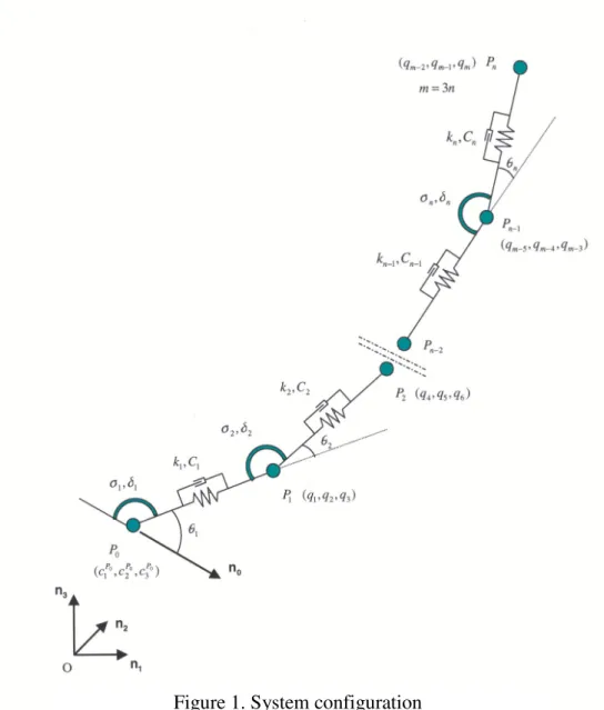
Figure 1 is a diagram of the structural system to be modelled. The numerical model operates in 3D in the time domain. It uses lumped-mass segments and includes the effects of tension and bending. Hydrodynamic lift and drag forces are applied to each segment, depending on the profile of the ocean currents. Added-mass effects are included as well as the effects of internal fluid flow. In essence, the riser is modelled as a multi-body dynamical system that is driven by time-varying external forces in accordance with the formalism developped by Kane.
The riser is represented as a beam of hollow circular section that is divided into N straight segments. In addition to gravity and other applied loads, the riser is subject to external
hydrodynamic forces due to the surrounding ocean, as well as internal dynamic forces due to an internal flow. The mass of each segment is lumped in equal portions at the endpoints of each segment. Beam longitudinal vibration is modelled by linear extensional springs and dampers; beam bending is modelled by rotational springs and dampers at the endpoints. The rotational spring constants at the joints between the segments are chosen as described by Huston [1990] using linear beam theory. The rotational damping coefficients are estimated from the large-deflection behaviour of beams, which has been demonstrated in [Banerjee 1993] and in [Banerjee et al 1997]. At present torsional effects within the segments and at the joints between segments are not included.
The formulation uses generalised coordinates {q} and generalised speeds {u} = {qdot}. The system to be solved is simply {xdot} = {f(t, {x}}. The solution is obtained using the robust implementation of the Runge-Kutta method provided in 'ode45' in MATLAB.
The internal forces are computed from a strain energy formulation.
3. Formulation and application of the external and internal hydrodynamic loads
The numerical model contains routines that formulate the fluid forces in terms of the external flow field, that is, the external fluid velocity and acceleration due to the 3D ocean currents. The driving forces and currents can be expressed as functions of time and position. Near-surface forcing is represented by Stokes' second-order waves. The relative velocities between the fluid and a segment are computed at the midpoints of the segment.
The external hydrodynamic loads are expressed in terms of the motion of the lumped masses and the motion of the surrounding fluid. The expressions for the hydrodynamic driving forces are evaluated using the relative velocity and acceleration of the fluid and the structure at each
segment. The relative velocity is used to compute the tangential, normal and bi-normal
components of the hydrodynamic forces at the centre of each segment. The details are given in [Raman-Nair and Baddour].
The forces which result from a fluid which flows inside the riser, are due to the changes in momentum that the internal fluid experiences in passing from one segment to another; these
forces are thus due to both changes in fluid speed and direction. A control-volume approach and Reynolds Transport Theorem are used in this formulation.
In addition to the external and internal fluid-induced loads, the lumped-mass model includes the effects of inertia (through the combinations of structural mass, added-mass and the
acceleration of the fluid relative to each segment), gravity, buoyancy and touchdown. If we suppose that one endpoint of riser is connected at the seabed, then once the numerical model detects that any other segment endpoint is below the seabed, a seabed reaction force is applied that can be an arbitrary function of the size, shape and weight of the segment, and the
geotechnical properties of the seabed. A segment can actually penetrate the seabed, if the properties of the seabed permit that.
This lumped-mass model has been validated against known analytical solutions for (i) an elastic catenary that is hanging under its own weight (no ocean current) [Irvine 1981], and, (ii) the large deflections of a cantilever beam [Bisshopp and Drucker 1945].
4. Sources of data for the external hydrodynamic loads
The NRC Institute for Aerospace Research (IAR) has over 40 years of experience
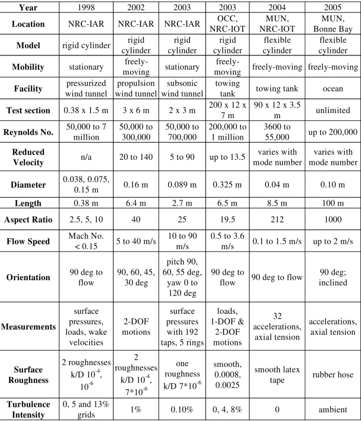
investigating vortex-induced oscillations (VIO) of tall, slender structures, including buildings, towers, chimneys and both cable-stayed and suspension bridges. This includes wind tunnel experiments to measure the unsteady loads for the Akashi Kaikyo and Tatara bridges in Japan. Recent investigations for vortex-induced vibrations (VIV) of large cables include wind tunnel experiments with rigid circular cylinders as summarized in Table 1.
Figure 2 shows the installation of a purpose-built VIV apparatus on the towing tank carriage at the NRC-IOT. This apparatus was designed and built by our commercial partner the Oceanic Consulting Corporation, with industry support through the DeepStar Project. This apparatus supports a rigid circular cylinder of length 6.3 m, diameter 0.325 m and aspect ratio 19.5. The apparatus is constructed in such a way that the cylinder (i) can be held fixed, (ii) is free to oscillate in only the cross-stream direction, (iii) is free to oscillate in both the streamwise and cross-stream directions, and, (iv) can be forced to oscillate in the cross-stream direction. A range
Figure 2. Oceanic Consulting Corporation's VIV test apparatus for the NRC-IOT towing tank carriage
of tow speeds up to 3.6 m/s was used thus providing results with Reynolds Numbers from 100,000 to over one million. Replaceable sleeves can be used to vary the surface roughness e.g. smooth, and with k/D values of 0.0008 and 0.0025. Tests were performed in smooth flow and two grids provided turbulence intensities of 4 and 8%. Details of the experimental apparatus and results from various test conditions can be found in reference [OCC 2004] and [Oakley 2004]. In a recent close collaboration with the Memorial University of Newfoundland (MUN), a flexible-riser model of length 8.5 m and diameter 4 cm was tested in the NRC-IOT towing tank; the results will be presented separately at this conference [Li 2005].
5. Example results
A typical set of predictions from this numerical model is given in the following example for a steel catenary riser with internal flow. The parameters of the riser are as follows: the initial length is 3000 m with a vertical extent of 2500 m and horizontal extent 1300 m. The internal diameter is 0.4 m, the external diameter is 0.5 m and Young’s modulus is 200 GPa. The conditions of the approach flow are a linear sheared current from 2 m/s at the surface to zero at a depth of 1000 m and now surface wave forcing. The density of the internal fluid is 800 kg/m3, the flow rate is 20 litre/sec which corresponds to a production rate of 10,000 barrels per day. The pressure of the internal fluid varies from 80 MPa at the base to 70 MPa at the top end. The formulation of the external hydrodynamic loads that are driving the system uses a mean drag coefficient, and RMS values for the fluctuating drag and lift forces, that are functions of the Reynolds Number for each segment; the Strouhal Number for vortex shedding is taken to be 0.2. Some results are given in the form of time-series in Figure 3, when the riser is modeled with 50 segments, for the tensile force, bending moment and maximum tensile stress.
6. Calibration and validation of the numerical model
The data from the OCC rigid moving-cylinder experiments can be used to “calibrate” the numerical model, when it is configured as a single segment with the same mass per unit length and damping characteristics as the OCC cylinder. Thus the values of CD, CL and CM from the OCC data for the tabulated values of Re, k/D, turbulence intensity and motion amplitude can be used as input data for the numerical model. The resulting motions can be compared with the experimental values.
A second “calibration” is possible using the data from the MUN flexible-riser experiments. Again, appropriate values of CD, CL and CM from the OCC data set can be used as input data. The resulting motions can be analyzed using the same modal analysis techniques as in the MUN data analysis.
Where large angles of inclination occur on the riser, the values of CD, CL and CM from the NRC-IAR inclined cylinder experiments.
Once suitable agreement has been attained for this comprehensive range of experimental parameters and motions, the numerical model will be considered “calibrated”.
7. Additional sources of experimental data
A facility which could add valuable insights is the NMRI Deep-Sea Basin, and, through an MOU between NRC-IOT and NMRI we will be working with NMRI researchers to pursue these advances.
Based on the recent success obtained with the 8.5 m flexible-riser model, it is planned to design, build and test a similar structure of length 100 m in open-ocean conditions at the
Memorial University Marine Station in Bonne Bay, Newfoundland. This site includes a shallow sill over which tidal currents flow with speeds typically up to 2 m/s, thus the intention is to test a horizontally-tensioned riser-model there. In the adjacent deeper water, the same model can be tested in an inclined mode.
8. The end product
The end product of this research will be a fully-calibrated, fully-validated numerical model for predicting the motions and stresses in flexible deep-water risers that are subject to hydrodynamic loadings due to surface wave and deep-ocean currents.
9. Discussion
In the absence of measurements of the motions of full-scale risers, model-scale experimental results at high Reynolds Numbers provide the only evidence to substantiate whether or not reliable predictions of the motions and stresses for deep-water risers can be made with numerical models. However it raises questions concerning the source of the hydrodynamic loads, that is, the type of experiments that are performed in order to obtain these loads.
a. Are the predictions conservative if we use data from rigid stationary circular-cylinder Figure 3. Results for a riser with internal flow
experiments?
b. Are the predictions improved if we use data from rigid circular cylinders which execute free 1-DOF oscillations in only the cross-stream direction?
c. How necessary is it to use data from rigid circular cylinders which execute free 2-DOF oscillations in both the streamwise and cross-stream direction;
d. Do data from rigid circular cylinders which execute forced oscillations in 1-DOF or 2-DOF produce reliable predictions?
e. Do the predictions depend strongly on the angle of inclination or angle of yaw of an inclined rigid cylinder or is it safe to use data from cylinders for which the flow is normal to the
longitudinal axis of the cylinder?
f. Is the only way to achieve reliable predictions to use the data from experiments with long slender flexible circular cylinders that are capable of responding in a high number of modes? 10. Summary
The lumped mass model provides a tool for simulation of motions and stresses in deep-water risers. The model had been validated for simple test cases. The model has been implemented with measured forcing functions for a particular riser, and provides a reasonable simulation of the motions and riser stresses.
The project data set covers a wide range of parameters and conditions. Verification and calibration of the model against this broad data set will ensure a robust model for numerical investigations and practical applications in fatigue analysis and mitigation.
11. Acknowledgements
The authors would like to acknowledge the assistance given in the preparation of this paper by several groups of people. Steve Zan, Guy Larose and Mike Savage of the NRC Institute for Aerospace Research provided the measured high Reynolds Number force time-series that were used in the example simulations. Don Spencer of Oceanic Consulting Corporation provided the high Reynolds Number experimental data for the in-water oscillating cylinder. Graduate students Xiangqun Li and Lin Zhu, and Professor Neil Bose of the Faculty of Engineering and Applied Sciences at the Memorial University of Newfoundland, provided the results from the flexible riser experiments. Finally, Fraser Davidson, Youyu Lu and John Loder of the Ocean Sciences Division at the Department of Fisheries and Oceans, provided the ocean current data.
12. References
W.Raman-Nair and R.E.Baddour, "Three-Dimensional Dynamics of a Flexible Marine Riser Undergoing Large Elastic Deformations", Multibody System Dynamics, vol.10, no.4, Nov 2003, pp 393 to 423.
C.M.Larsen, "Flexible Riser Analysis-Comparison of Results from Computer Programs", Marine Structures, vol. 5, 1992, pp103 to 119.
T.R.Kane and D.A.Levinson, "Dynamics : Theory and Applications", McGraw Hill Inc.,1985. R.L.Huston, "Multibody Dynamics", Butterworth-Heinemann, 1990, pp350 to 357.
A.K.Banerjee and S.Nagarajan, "Efficient Simulation of Large Overall Motion of Beams Undergoing Large Deflection", Multibody System Dynamics, vol.1, no.1, Mar 1997, pp 113 to126.
A.K.Banerjee, "Dynamics and Control of the WISP Shuttle-Antennae System", The Journal of the Astronautical Sciences, vol. 41, no.1, Jan-Mar 1993, pp 73 to 90.
L.D.Landau and E.M.Lifshitz, "Fluid Mechanics", Pergamon Press, 1959, pp.35. R.D.Blevins, "Flow-Induced Vibration", Krieger Publishing Co., 2000.
Jakobsen, J.B., G.L. Larose and M.G. Savage, “Instantaneous wind forces on inclined circular cylinders in the critical Reynolds number range”, in Proc. of 11th Int. Conference on Wind Engineering, Lubbock Texas, June 2003, pp. 2165-2173.
W-J.Kim and N.C.Perkins, "Two-Dimensional Vortex-Induced Vibration of Cable Suspensions", Journal of Fluids and Structures, vol. 16(2), 2002, pp 229 to 245.
Larose G.L., J.B. Jakobsen and M.G. Savage, “Wind-tunnel experiments on an inclined and yawed stay-cable model in the critical Reynolds number range”, in Proc. of the 5th Int.
Symposium on Cable Dynamics, Santa Margerita Ligure, Italy, Sept. 11-15, 2003, pp. 279-286. X.Li, N.Bose, L.Zhu and D.Spencer, "Multi-modal VIV Tests for a Highly Flexible Model Riser", Proceedings of the International Symposium on Technology of Ultra Deep Ocean Engineering", Tokyo, Japan, 01 and 02 February 2005.
O.H.Oakley and D.Spencer, “DeepStar High Reynolds Number Cylinder Test Program”, Proceedings of the Deepwater Offshore Technology Conference, DOT’04, New Orleans, Nov 2004.
"High Reynolds Number Cylinder Vortex Induced Vibration Test Apparatus", Ocean Consulting Corporation report INT062-01, January 2004.
F.M.White, "Fluid Mechanics", McGraw Hill Inc., 1999, 4th ed., Chap 3.
S.J.Zan, "Experiments on Circular Cylinders in Crossflow at Reynolds Numbers up to 7 Million", Proceedings of the 5th International Colloquium on Bluff Body Aerodynamics and Applications (BBAA-V), Ottawa, Canada, July 2004.
Table 1. Experimental conditions for the various test facilities and model types
Year 1998 2002 2003 2003 2004 2005
Location NRC-IAR NRC-IAR NRC-IAR NRC-IOTOCC, NRC-IOTMUN, Bonne BayMUN, Model rigid cylinder cylinderrigid cylinderrigid cylinderrigid cylinderflexible cylinderflexible Mobility stationary movingfreely- stationary movingfreely- freely-moving freely-moving
Facility wind tunnelpressurized wind tunnelpropulsion wind tunnelsubsonic towing tank towing tank ocean Test section 0.38 x 1.5 m 3 x 6 m 2 x 3 m 200 x 12 x 7 m 90 x 12 x 3.5 m unlimited Reynolds No. 50,000 to 7 million 50,000 to 300,000 50,000 to 700,000 200,000 to 1 million 3600 to 55,000 up to 200,000
Reduced
Velocity n/a 20 to 140 5 to 90 up to 13.5 mode numbervaries with mode numbervaries with Diameter 0.038, 0.075, 0.15 m 0.16 m 0.089 m 0.325 m 0.04 m 0.10 m
Length 0.38 m 6.4 m 2.7 m 6.5 m 8.5 m 100 m
Aspect Ratio 2.5, 5, 10 40 25 19.5 212 1000
Flow Speed Mach No. < 0.15 5 to 40 m/s 10 to 90 m/s 0.5 to 3.6 m/s 0.1 to 1.5 m/s up to 2 m/s Orientation 90 deg to flow 90, 60, 45, 30 deg
pitch 90,
60, 55 deg, yaw 0 to
120 deg
90 deg to
flow 90 deg to flow inclined90 deg;
Measurements surface pressures, loads, wake velocities 2-DOF motions surface pressures with 192 taps, 5 rings loads, 1-DOF & 2-DOF motions 32 accelerations, axial tension accelerations, axial tension Surface Roughness 2 roughnesses k/D 10-4, 10-6 2 roughnesses k/D 10-4, 7*10-6 one roughness k/D 7*10-6 smooth, 0.0008, 0.0025 smooth latex
tape rubber hose
Turbulence