Capillary Densification and Adhesion Tuning
of Aligned Carbon Nanotube Arrays
for Shape-Engineerable Architectures
by
Ashley L. Kaiser
B.S., Chemical Engineering
University of Massachusetts Amherst (2017)
Submitted to the Department of Materials Science and Engineering
in partial fulfillment of the requirements for the degree of
Master of Science in Materials Science and Engineering
at the
MASSACHUSETTS INSTITUTE OF TECHNOLOGY
June 2019
© Massachusetts Institute of Technology 2019. All rights reserved.
Author . . . .
Department of Materials Science and Engineering
May 23, 2019 (Seminar Completed May 21, 2019)
Certified by . . . .
Brian L. Wardle
Professor of Aeronautics and Astronautics
Thesis Supervisor
Certified by . . . .
Carl V. Thompson
Stavros Salapatas Professor of Materials Science and Engineering
Thesis Reader
Accepted by . . . .
Donald R. Sadoway
Chairman, Departmental Committee on Graduate Studies
Capillary Densification and Adhesion Tuning
of Aligned Carbon Nanotube Arrays
for Shape-Engineerable Architectures
by
Ashley L. Kaiser
Submitted to the Department of Materials Science and Engineering
on May 23, 2019 (Seminar Completed May 21, 2019), in partial fulfillment of the requirements for the degree of
Master of Science in Materials Science and Engineering
Abstract
The advantaged intrinsic and scale-dependent properties of aligned nanofibers (NFs), such as carbon nanotubes (CNTs), and their ability to be self-assembled by capillary forces mo-tivates their use as shape-engineerable materials. In order to achieve facile and accurate patterning and densification of NFs into new architectures, a mechanistic understanding of the parameters governing NF synthesis, densification, and substrate adhesion is needed. Here, parametric experiments and models are developed to evaluate the scaling of NF-substrate adhesion strength (Fa) of mm-scale tall aligned CNT arrays as a function of CNT
growth time (tg), and to control the solvent-based capillary densification of sub-mm-scale
tall CNT arrays into cell and pin structures, which have tunable geometries based on CNT height, Fa, and, if used, the as-grown CNT array pattern size (s). One-dimensional scaling
relations are presented that accurately predict the morphology of these capillary-densified CNTs exhibiting multiple spatial scales, including long-range cellular networks formed from bulk-scale CNT arrays, and solid, micron-scale pins formed via the densification of patterned CNT arrays below and at the critical s that separates cell vs. pin formation. The effective CNT array elastic modulus (E), and not the orders-of-magnitude higher isolated CNT axial modulus, is found to govern the width, area, wall thickness, and volume frac-tion of the densified cells and pins. E is about an order of magnitude smaller for pins as compared to cell networks formed from bulk-scale (i.e., non-patterned) CNT arrays, and patterning therefore results in pins with a lower packing density (commensurate with dou-ble the wall thickness) and a larger characteristic spacing than bulk cell networks. Further increasing s recovers the bulk-scale cell scaling relations, as the cell geometry plateaus for s' 1000 µm. Additional tuning of the cell network geometry is possible by altering Faviaa simple post-growth annealing step. However, while controlling this adhesion is needed for bulk-scale manufacturing and application-specific performance, experimental and theoreti-cal approaches to date have neglected to address the stheoreti-caling of Fawith tg, a crucial process
parameter governing CNT synthesis, structure, and properties. Here, the non-monotonic scaling of Fa with tgis measured experimentally via uniform tensile CNT array separation
from a flat growth substrate and modeled analytically based on atomic and meso-scale CNT evolution using contact mechanics. CNT growth termination is marked by a reduction in
CNT number density and a plateau in array height, signifying the transition between two distinct process-structure-property scaling regimes. At this growth termination point, ex-periments and modeling indicate a one- and two-orders-of-magnitude increase in Fa and
E, respectively. Here, the observed increase in CNT wall thickness and sp3 bond char-acter with tg shows that the accumulation of turbostratic carbon species in the CNT array
contributes to the evolving mechanical response. Future paths of study are recommended to extend this work towards two-dimensional capillary densification of NF arrays and Fa
tunability via post-processing, which would allow for the densification of taller NF arrays (towards mm- and cm-scales) to expand the suitability of these materials for a broader range of applications. Collectively, these results enable the use of capillary densification and tunable NF-substrate adhesion for the design and manufacture of bulk nanoengineered materials and emerging nanoscale technologies.
Thesis Supervisor: Brian L. Wardle
Acknowledgements
This thesis represents a significant chapter of both personal and professional growth in my life while at MIT, and it is the result of jumping headfirst into an experience that would inspire scientific thinking, challenge and extend limits, and ultimately provide a valuable opportunity for growth and learning. I am grateful to many people who have made this work possible, and I would first like to thank my advisor, Prof. Brian Wardle, without whom none of this work could have happened. I appreciate that he allowed this project to be my own, but steered me in the right direction when he thought I needed it. Thanks to all of my research collaborators and the members of necstlab for their help and advice throughout this project − experiencing MIT life and adventures with you was a true joy.
A special thanks to Itai, who first welcomed me to necstlab as a 2016 MRL Summer Scholar, and who pushed me very hard in my first internship at MIT when I was still new to graduate-level research. Your enthusiastic guidance, constructive feedback, and willingness to share skills, knowledge, and expertise was priceless, and that was a big part of why I returned to MIT/necstlab for graduate school and accomplished so much in a short time. You helped show me that I could keep extending my capabilities past even what I thought was possible, time and time again. Thank you!
I would also like to thank Profs. Carl Thompson and Michael Cima in DMSE, and my UROPs, Amy and Azreen, for their contributions and support throughout these projects. Thanks to the staff at CMSE/MRL and ISN at MIT, whose guidance on experimental char-acterization tools was quite valuable for this thesis. A special thanks to Patrick Boisvert, who taught me the beauty of SEM during my first week ever at MIT as a Summer Scholar, and who continued to inspire my love of electron microscopy and art-science in the years that followed. Many thanks to my wonderful mentors and role models from UMass Amherst,
whose advice and teachings inspired me to pursue graduate school and follow my scientific and engineering passions - Profs. Dimitrakopoulos, Schiffman, Maroudas, and Forbes, as well as Tami Paluca and Greg Brown. Your example and positive impact will stay with me forever.
Finally, I must express my very profound gratitude to my friends, family, and Russ for their unconditional support throughout these two years of study, and throughout the pro-cess of researching and writing this thesis. A very special thanks to my wonderful parents, who taught me the grit, wit, and determination to succeed, and who have provided me with continuous encouragement, unfailing positivity, and a knowing smile throughout the ups and downs to remind me that ‘It’s all part of the experience, honey’ and at the end of the day, ‘It’s good. It’s good!’ While life is not monotonic, experience certainly is, and this accomplishment would not have been possible without them. Thank you!
“In every walk with nature, one receives far more than he seeks.” −John Muir
Funding acknowledgements: This work was partially supported by Airbus, ANSYS, Em-braer, Lockheed Martin, Saab AB, Saertex, and Teijin Carbon America through MIT’s Nano-Engineered Composite aerospace STructures (NECST) Consortium, the U. S. Army Research Laboratory and the U. S. Army Research Office through the Institute for Sol-dier Nanotechnologies (ISN) under contract number W911NF-13-D-0001, the U.S. Army Research Office under contract W911NF-07-D-0004, and the National Aeronautics and Space Administration (NASA) Space Technology Research Institute (STRI) for Ultra-Strong Composites by Computational Design (US-COMP), grant number NNX17AJ32G. A.L.K. was supported by the Department of Defense (DoD) through the National Defense Science and Engineering Graduate Fellowship (NDSEG) Program. This work made use of the MIT MRSEC Shared Experimental Facilities supported by the National Science Foun-dation under award number DMR-0819762, and was carried out in part through the use of MIT’s Microsystems Technology Laboratories.
Contents
Acknowledgements 5
Contents 7
List of Figures 11
List of Tables 23
Abbreviations and Symbols 25
1 Introduction 31
1.1 Overview: High Density Aligned Nanofiber Architectures for Next-Generation Multifunctional Materials . . . 32 1.2 Thesis Outline . . . 35
2 Background 39
2.1 Aligned Nanofiber Densification via Elasto-Capillary Self-assembly . . . . 40 2.2 Interfacial Substrate Adhesion in Aligned Nanofiber Systems and Effects
on Elasto-Capillary Forming . . . 45 2.3 Conclusions . . . 49
3 Objectives and Approach 51
3.1 Objectives . . . 51 3.2 General Approach . . . 51 3.2.1 Capillary Densification of Bulk-scale Aligned CNT Arrays . . . 52
3.2.2 Capillary Densification of Patterned Aligned CNT Arrays . . . 52 3.2.3 CNT-Substrate Adhesion Scaling with CNT Growth Time . . . 53
4 Capillary Densification of Bulk-scale Aligned CNT Arrays 55
4.1 Introduction to CNT Capillary Densification . . . 55 4.2 Capillary Densification of Bulk-scale CNT Arrays . . . 58 4.2.1 Experimental . . . 58
4.2.1.1 Aligned MWCNT Array Synthesis and Cementation Post-Processing . . . 58 4.2.1.2 Capillary Densification Procedure . . . 59 4.2.1.3 CNT Cell Geometry Characterization via SEM and
Op-tical Image Analysis . . . 60 4.2.2 Model Development for Bulk-scale CNT Capillary Densification . . 62
4.2.2.1 One-Dimensional Scaling Relations for Cell Wall Thick-ness, Width, and Area . . . 63 4.2.2.2 Cell Geometry as a Function of CNT Height . . . 66 4.3 Results and Discussion . . . 68 4.3.1 Effect of CNT-Substrate Adhesion on Cell Network Formation . . . 68 4.3.2 Modeling Results for CNT Cell Geometry Scaling Relations . . . . 70 4.4 Conclusions and Recommendations for Future Work . . . 75
5 Capillary Densification of Patterned Aligned CNT Arrays 77
5.1 Introduction to Capillary Densification of Patterned CNT Arrays . . . 78 5.2 Capillary Densification of Critical-Pattern-Sized Aligned CNT Arrays into
Pins . . . 82 5.2.1 Experimental . . . 82 5.2.1.1 Substrate Patterning and Aligned MWCNT Synthesis . . 82 5.2.1.2 Capillary Densification Procedure and Pin
Characteriza-tion via SEM . . . 84 5.2.2 Model Development for Patterned CNT Capillary Densification . . 85
5.2.2.1 One-Dimensional Scaling Relations for Pin Wall Thick-ness and Critical Pattern Size . . . 85 5.2.2.2 Pin Geometry as a Function of CNT Height . . . 87 5.2.3 Results and Discussion . . . 88 5.2.3.1 Comparison of O2-treated CNT Pins and Bulk-scale Cells 88
5.2.3.2 Comparison of O2-treated and Non-treated Pins . . . 92
5.3 Capillary Densification of Patterned Aligned CNT Arrays: Beyond the Critical Pattern Size . . . 94 5.3.1 Experimental . . . 95
5.3.1.1 Substrate Patterning, Aligned MWCNT Array Synthe-sis, and Capillary Densification Procedure . . . 95 5.3.1.2 Patterned CNT Cell and Pin Geometry Characterization
viaSEM . . . 96 5.3.2 Results and Discussion . . . 98
5.3.2.1 Transition from CNT Pin to Cell Formation Beyond the Critical Pattern Size . . . 98 5.3.2.2 Patterned Cell Geometry Scaling with CNT Height and
Pattern Size . . . 99 5.4 Conclusions and Recommendations for Future Work . . . 103
6 CNT-Substrate Adhesion Scaling with CNT Growth Time 107
6.1 Introduction to Substrate Adhesion in Aligned Bulk Nanofiber Arrays . . . 108 6.2 Substrate Adhesion Scaling with CNT Growth Time in Aligned CNT Arrays 110 6.2.1 Experimental . . . 110 6.2.1.1 Millimeter-tall Aligned MWCNT Array Synthesis . . . . 111 6.2.1.2 CNT-Substrate Adhesion Force Quantification via
Ten-sile Testing . . . 111 6.2.1.3 CNT Morphology Characterization via SEM and TEM . 113 6.2.1.4 Raman Spectroscopy Analysis . . . 113 6.2.2 CNT Array Process-Structure Results . . . 115
6.2.2.1 CNT Height and Wall Thickness Evolution . . . 115
6.2.2.2 CNT Bonding Character Evolution . . . 118
6.2.3 Model Development for CNT-Substrate Adhesion . . . 120
6.2.3.1 Model Assumptions and Derivation . . . 120
6.2.3.2 Bimodal Scaling of Effective CNT Array Elastic Modu-lus and Substrate Adhesion with Growth Time . . . 126
6.2.4 Results and Discussion . . . 129
6.2.4.1 Mechanistic Insights from CNT-Substrate Adhesion Model129 6.2.4.2 Model Limitations and Potential Additions . . . 131
6.3 Conclusions and Recommendations for Future Work . . . 133
7 Conclusions and Recommendations 137 7.1 Summary of Thesis Contributions . . . 138
7.2 Recommendations for Future Work . . . 143
List of Figures
1.1 Conceptual diagram of (a) single-walled carbon nanotube (SWCNT) and (b) multi-walled carbon nanotube (MWCNT[1]) showing typical dimen-sions of length, width, and inter-tube separation in MWCNTs, as presented in Ref. 13. (c) Plot of the reported mechanical properties of CNTs (here specific modulus versus specific strength), including a comparison of the mechanical properties of composite materials to other engineering materi-als, adapted from Ref. 14. . . 33
1.2 Plot showing the adoption of advanced carbon-based composites into the total structural weight of commercial aircraft, with the upper and lower S-curves representing CF- and CNT-based structural composite materials, respectively.[19] . . . 34
1.3 Application overview of aligned NFs and nanoengineered composite ma-terials incorporating dense CNT reinforcement. High-density aligned NF architectures including polymer nanohair arrays,[40] patterned CNTs,[27] and multifunctional CNT assemblies.[1] . . . 35
2.1 Overview and illustration of the capillary densification of NFs, such as aligned CNT arrays, into cell networks or pin architectures (imaged here by SEM) as a function of CNT height, pattern size, and CNT-substrate adhesion considerations. . . 41
2.2 Overview of experimental results for the capillary densification of bulk-scale CNT arrays into cell networks. (a-d) Schematics illustrating the for-mation of cellular structures in vertically aligned CNT arrays of height h as presented in Ref. 65. (e-h) SEM images showing the formation of cellular patterns by the evaporation of liquids from vertically aligned CNT arrays, with the arrow depicting the cell width (w), as presented in Ref. 65. (i-j) SEM images showing h dependence of the capillary-densified CNT cell networks, as presented in Ref. 66. (k) Previously reported w of CNT cells made from CNTs with diameters Dcnt ∼ 5 – 15 nm to 15 – 60 nm ( , and
, respectively),[62,65–71] and the linear scaling relation proposed in Ref. 65. 42
2.3 Overview of extant experimental and modeling results for the capillary den-sification of patterned CNT arrays into cell networks and solid pins. (a-e) SEM images showing variation of structure, shape, and orientation using patterned aligned CNT arrays, as presented in Ref. 65. (f) Illustrations showing the fabrication of CNT pins by patterned CNT growth followed by self-directed capillary densification, as presented in Ref. 30. (g) Plot showing the effect of CNT microstructure dimensions on cell versus pin formation that compares analytical models to measurements of cylindrical microstructures, which were O2 plasma etched to remove the top layer of
entangled CNTs prior to densification, as adapted from Ref. 30. . . 43
2.4 Overview of NF-substrate adhesion for aligned NF arrays, such as CNTs, and examples of nanoengineered CNT composites and thermal interface material applications, where weak and strong substrate adhesion are desir-able, respectively.[1] . . . 46
2.5 Overview of vertically aligned MWCNT array growth on a silicon wafer substrate consisting of an iron catalyst layer and an alumina underlayer. (a) Illustration and transmission electron microscopy (TEM) images showing how the CNT array evolves after growth initiation throughout two growth modes separate by growth termination, here termed Mode 1 (steady growth) and Mode 2 (post-growth, turbostratic carbon (t-C) deposition). CNT nu-cleation is not shown. Carbon deposition on the CNT array increases the CNT wall thickness (a) and thereby the outer radius (Ro) at constant inner
radius (Ri). (b-d) Exemplary SEM images of h increasing with tg, adapted
from Ref. 118. (e) Previously reported h as a function of tgillustrating how
hplateaus when tgincreases beyond the steady growth mode and enters the
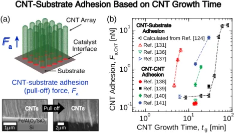
t-C deposition mode after growth termination.[56,58,104–106,119–124] . . . 47 2.6 Overview of the processing effects of tg on CNT-substrate adhesion. (a)
Illustration showing that the pull-off force (Fa) is obtained by separating an
aligned CNT array from its catalyst layer/substrate (Fe/Al2O3/SiO2/Si), as
shown by two SEM images demonstrating CNT array-substrate adhesion. (b) Plot showing the substrate adhesion force per CNT (Fa,CNT)[124,131,136,137]
and CNT-CNT adhesion force[138–141]scaling with tg. . . 48
4.1 Overview of CNT cellular network modeling geometry. (a) 1D schematic illustrating CNT self-organization as the solvent’s meniscus recedes due to evaporation. (b) Side view illustration showing h, w, and cell wall thickness (tcl), and top view illustration showing the CNT cell wall length (b) and
repeat unit (2D size of (w + tcl) × b). . . 56
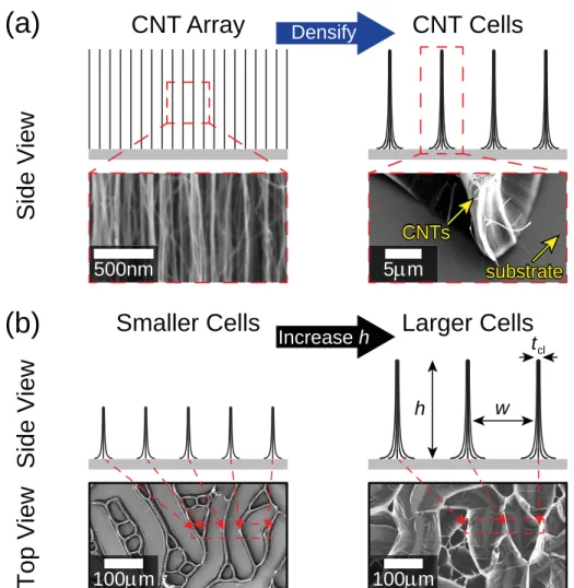
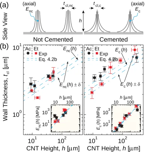
4.2 Capillary-mediated densification of aligned CNT arrays into 2D cellular networks. (a) Illustrations and SEM images demonstrating the formation of cells from CNT arrays. (b) Side view illustrations and top view SEM im-ages of CNT cell networks showing that h governs w and tclof the resulting
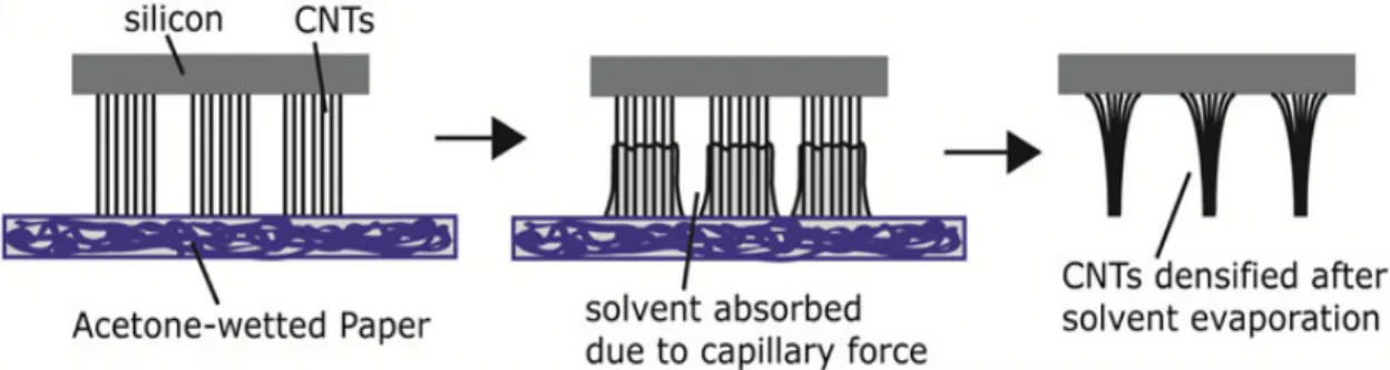
4.3 Illustrations of the experimental setup for the bulk-scale capillary densi-fication of aligned CNT arrays and the mechanism of the paper-mediated densification, as presented in Ref. 174. In this gentle process, the CNTs are fully wetted by solvent-soaked paper, where the paper acts as a hydro-dynamic damper to allow the solvent to move into the CNT forest slowly.[174] 60
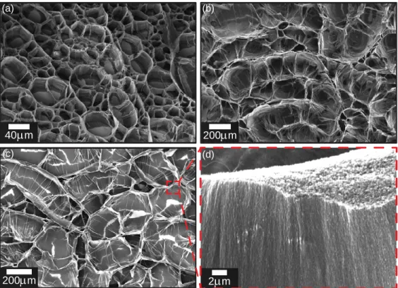
4.4 Imaging of the capillary-mediated densification of bulk-scale aligned CNT arrays into 2D cellular networks. Top view SEM images demonstrate the formation of cells from (a) 35 µm-tall CNT as-grown array and (b) 300 µm-tall cemented CNT array using acetone densification. (c) Top view SEM image of a cell network formed from a 50 µm-tall CNT array using ethanol and (d) corresponding side view SEM image of the dense CNT cell wall structure showing that CNTs maintain their vertical alignment after capillary densification. . . 61
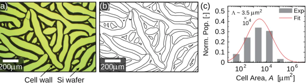
4.5 Exemplary optical microscope images and plot illustrating how the CNT cell area (A) was estimated. To approximate A, (a) raw optical microscope images were first processed in ImageJ using the built-in threshold and color inversion filters (where the green in the images is the Si wafer, and the black lines are the cell walls comprised of densified aligned CNTs), and then (b) ImageJ’s particle size analysis function was used to outline and measure the voids that comprise the 2D CNT cellular network, which leads to (c) histograms of the cell area distribution for each sample. As further dis-cussed in the main text, these histograms are then analyzed via log-normal statistics to yield the arithmetic mean (Λ). . . 62
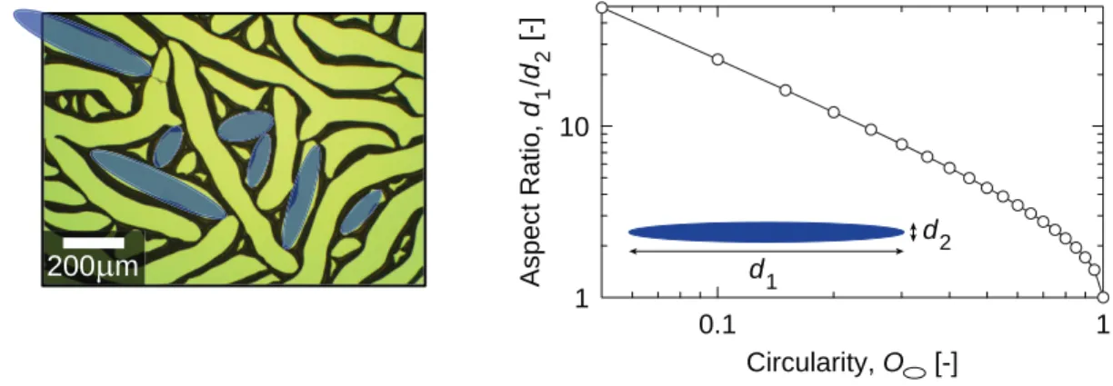
4.6 Illustration of elliptical estimate of CNT cell geometry and plot of an ide-alized ellipse’s aspect ratio (d1/d2) vs. its circularity (O ). . . 65
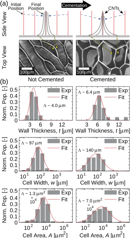
4.7 Effect of CNT-substrate adhesion on cell network formation, either base-line non-cemented CNTs (left) or cemented CNTs (right) made via post-processing. (a) Side view illustrations and top view SEM images of cell networks formed from ∼ 35 µm-tall CNT arrays. (b) Exemplary distribu-tions (for CNT height ∼ 35 µm) of the cell wall thicknesses, cell widths, and areas for CNT cell networks formed using non-cemented (left) and ce-mented (right) CNT arrays. Evaluated arithmetic mean (Λ) values indicate that cemented CNTs form larger cells with thicker walls than non-cemented CNTs. . . 69 4.8 Cell geometry evolution with h for non-cemented (nc, left) and cemented
(c, right) CNTs densified via acetone and ethanol (→ Ac and Et). (a) Illus-trations of different effective wall elastic moduli (E) giving rise to thick-nesses (tcl) of cells formed from nc- and c-CNTs (→ Enc, tcl,nc, and Ec, tcl,c,
respectively). (b) Plots showing that ∂ Ec/∂ h < ∂ Enc/∂ h leads to faster tcl
scaling with h (eqn 4.2b, see inset) for c-CNTs. . . 72 4.9 Cell geometry evolution with h for non-cemented (nc, left) and cemented
(c, right) CNTs densified via acetone and ethanol (→ Ac and Et). (a) Illus-trations of different densification factors (Ξ) giving rise to thicknesses and widths (tcland w) of cells formed from nc- and c-CNTs (→ Ξnc, tcl,nc, wnc
and Ξc, tcl,c, wc, respectively). (b) Plots illustrating that w scales faster with
h(eqn 4.5, see inset) for c-CNTs because Ξc > Ξnc. . . 73
4.10 Cell geometry evolution with h for non-cemented (nc, left) and cemented (c, right) CNTs densified via acetone and ethanol (→ Ac and Et). (a) Il-lustrations of different effective wall elastic moduli (E) and densification factors (Ξ) giving rise to thicknesses and widths (tcland w) of cells formed
from nc- and c-CNTs (→ Enc, Ξnc, tcl,nc, wnc and Ec, Ξc, tcl,c, wc,
respec-tively). (b) Plots demonstrating that while cell area (A) scales faster with h(eqn 4.7b, see inset) for c-CNTs, cell circularity (→ Onc and Oc) is
5.1 Overview of CNT pin densification and modeling geometry. (a) 1D illus-tration showing an aligned CNT array on a patterned substrate undergoing CNT self-assembly as the solvent evaporates, shown here for CNTs with the entangled CNTs removed via O2plasma treatment. (b) Side view
illus-tration showing h, scr, and tp, and top view illustration showing tpresulting
from 1D densification and the pin unit cell of size scr x l used in eqn 5.3,
where l scr to consider only 1D effects. . . 79
5.2 Capillary-mediated densification of patterned aligned CNT arrays forming cell networks or pin structures based on the pattern size, s. (a) Illustra-tions and SEM images show selective CNT array growth on mechanically-scribed substrates, including the synthesis-induced entangled CNTs on top of the array. (b) Illustrations and SEM images show how scr separates CNT
cell formation (s > scr) from pin formation (s ≤ scr) at a given h. Here, h
and s govern w, tcl, and tp, shown here for CNTs with the entangled CNTs
removed via O2plasma treatment. . . 81
5.3 Top view images of 70 µm-tall patterned aligned CNT arrays before and after growth via CVD. Optical and SEM images illustrate that the mechan-ically patterned substrate of grid size (pattern size) s = 200 µm yields CNT array growth only in the unscribed rectangular grids. . . 83
5.4 Top view images of 70 µm-tall patterned aligned CNT arrays after capillary-mediated densification. SEM images show that CNT arrays of s = 100 µm and 200 µm were densified into solid pins (i.e., no cells) while maintaining vertical CNT alignment. . . 85
5.5 Morphological evolution of aligned CNT (a) cells and (b) pins formed from the bulk-scale (see Chapter 4) and patterned densification of O2
-plasma-treated CNT arrays, respectively, along with standard error. Schematics illustrate the structural parameters, including t, w, scr, Ξ, E, and h for cells
(tcl, w, Ξcl, Ecl) and pins (tp, scr, Ξp, Ep). Plots of t vs. h show that tp∼ 2
× tcl, and exemplary SEM images show 10 µm-tall CNT cell and pin wall
thicknesses (see insets). Plots of E vs. h show that Ecl∼ 10 × Ep, and inset
SEM images show exemplary 30 µm-tall cells and pins. Finally, plots of Ξ vs. h show that Ξcl∼ 1.3 × Ξp, and inset SEM images show exemplary 50
µm-tall cells and pins. . . 89
5.6 Previously reported w of cells made from CNT arrays of s ≥ 1000 µm ( ) via bulk-scale densification[32,33,62,65–71,151,194] alongside the linear w vs. hscaling relation proposed in Ref. 65. Also shown are previously reported scr of pins ( ) formed by densifying patterned CNT arrays[30] and scr of
pins reported in this work ( ) alongside the scaling relation proposed in Ref. 39, which is shifted upwards for pin formation, as scr ∼ 5 × w for the
CNT arrays studied here. . . 91
5.7 Effect of O2 plasma treatment (i.e., post-growth entangled CNT layer
re-moval from aligned CNT arrays): (a) No O2treatment (nO-CNTs) and (b)
O2 treatment (O-CNTs) on CNT pin morphology resulting from capillary
densification at scr as a function of h. Here, δ represents the standard
er-ror of the measured variables used in the model calculation. SEM images show that scr for exemplary 20 µm-tall CNT arrays is larger for nO-CNTs.
Plots show that O2treatment yields improved scaling relations as derived
viathe proposed elasto-capillary model for both tpand scr due to reduced
5.8 Capillary-mediated densification of patterned aligned CNT arrays into cel-lular networks and solid pins based on s on the Si wafer growth substrate. (a) Illustrations and top view SEM images of CNTs with height (h) of 70 µm demonstrate that s governs the geometry of the densified CNT struc-tures, where scr separates cell formation (s > scr) from pin formation (s ≤
scr) for a given h. Larger pattern sizes (400 µm shown here) yield patterned CNT cells with width w and wall thickness tcl, while smaller pattern sizes
(100 µm shown here) yield solid CNT pins with wall thickness tp. . . 96
5.9 Effect of s on CNT cell and pin formation and the corresponding cell and pin wall thicknesses resulting from the capillary densification of 70 µm-tall CNT arrays with scr ≈ 230 µm, including arithmetic means (Λ). Top view
SEM images show (a) cell networks formed from a large pattern size (s = 500 µm > scr) with an exemplary normal distribution of tcl (average cell
width ≈ 80 µm) and (b) solid pins formed from a small pattern size (s = 200 µm < scr) with an exemplary normal distribution of tp. Here, the CNT
Vf in the cell and pin walls is ≈ 18%. . . 97
5.10 Phase diagram illustrating the critical pattern size scr vs. h separating cell
vs. pin formation for CNT arrays undergoing patterned capillary-mediated densification, with the standard error (δ ) plotted based on averages of the experimental measurements used in the scaling relation. Cell formation be-gins when s > scr, while pins form when s ≤ scr, following the same scaling
relation as w evolution with h for 1D bulk-scale capillary densification, as walso scales as h8/9.[33] Here, δ represents the standard error of the mea-sured variables used in the scaling relation. SEM images show CNT cells and pins at exemplary scr values (30, 100, and 230 µm) and corresponding
5.11 Effect of h on cell geometry resulting from patterned capillary-mediated densification. (a) For a fixed s of 500 µm, w increases with h because taller CNTs can more readily densify into larger cells, similar to the w scaling in bulk-scale capillary densification. (b) Exemplary log-normal distribution of w for the CNT cell network formed for s = 500 µm and h = 20 µm, exhibiting an arithmetic mean (Λ) of w ≈ 59 µm ± 6 µm. . . 100
5.12 Previously reported w of CNT cells made via patterned capillary densifi-cation of CNT arrays as a function of s, where h ∼ 1 – 50 µm to 60 – 750 µm ( and , respectively), showing how w generally increases with h.[30,32,33,65,66,151,194] The linear scaling relation shows how w increases with s until the transition from patterned to bulk-scale capillary densifica-tion occurs at s ∼ 1000 µm, where the average w plateaus as the system enters the bulk-scaling regime valid for large s values.[33] . . . 101 5.13 Patterned vs. bulk-scale cell geometry evolution with h and s. Plots show
how (a) w, (b) tcl, (c) Vf, and (d) E evolve with h and s for CNT arrays
undergoing capillary-mediated densification. Larger w, Vf, and E values
and correspondingly lower tcl values are observed on average for larger
pattern sizes, approaching bulk-scale behavior beyond s ∼ 1000 µm.[33] . . 102
6.1 Overview of the tensile testing setup for an aligned CNT array to determine its adhesion to the substrate (Fa) and post-test structural characterization of
the CNT array-substrate interface, as adapted from Ref. 124. (a) Illustra-tions and optical images showing the measurement of Fain a tensile tester
via vertical CNT array pull-off at the CNT-carbon cap-Fe catalyst inter-face with work of adhesion γs. The as-grown CNT array (attached to its Si
wafer growth substrate) is carefully bonded to two aluminum SEM stubs with silver epoxy prior to CNT removal. (b) Illustration showing the imag-ing and samplimag-ing locations of the separated CNT array-substrate interfaces for CNT characterization via Raman spectroscopy, SEM, and TEM. . . 112
6.2 Exemplary and representative TEM micrographs of CNTs after CNT ar-ray tensile testing. (a) Illustration showing the total CNT wall thickness (a) comprised of inner sp2 CNT walls and outer turbostratic carbon (t-C) layers. (b-f) TEM micrographs showing an increase in both a and the num-ber of disordered carbon layers surrounding the CNT walls as tg increases
from 9 to 80 mins, with the inner diameter remaining constant at ∼ 6 nm, as adapted from Ref. 124. The sample preparation of the TEM specimens was not limited to a specific location in the CNT array, and so the measured a values represent an average throughout the array for each tg. When the
CNTs remain in the CVD furnace for long values of tg, additional carbon
is deposited on the CNT walls by using them as a template to form slightly disordered t-C layers surrounding the CNTs. The turbostratic layers appear more ordered closest to the original ∼ 3–6 CNT walls due to the templating effect, and they become more disordered towards the outer CNT edges as tgincreases. . . 116
6.3 Morphological evolution of vertically aligned MWCNT arrays as a func-tion of tg. (a) SEM images of the middle (∼ h/2) of CNT arrays[124] show
the structural evolution and increasing CNT wall thickness (a) as tg
in-creases. (b) Plot showing how CNT height (h)[124] evolves as a function of tgin two distinct modes, which are separated by CNT growth termination
occurring at ∼ 40 min. A bilinear fit denotes the transition between Mode 1 (steady growth to termination) and Mode 2 (termination to t-C deposition), and an autocatalytic fit to describe the continuous h scaling with tg.[228,229]
(c) Plot and quadratic fit showing the scaling of a with tgthroughout Mode
6.4 Structural evolution of aligned CNT arrays as a function of tgcharacterized
by Raman spectra taken at the bottom of the CNT array after separation from the substrate. (a) Raman spectra of CNT arrays grown for tgranging
from 9 to 80 min[124]and corresponding fit functions. The D- and G-peaks broaden as tg increases, signifying that a higher percentage of defective,
non-sp2 carbon is present at longer tg in Mode 2. (b) Plot showing the
evolution of the intensity (ID/IG) and area (AD/AG) ratios of the D- and
G-bands with tg. The higher ratios observed after growth termination at
∼ 40 min show that the overall CNT array defect density increases as t-C is deposited on outer CNT walls. (c) Plot showing the evolution of the half width at half maximum (H) of the D- and G-bands with tg. . . 119
6.5 Adhesion mechanism and parameters for modeling the effective CNT ar-ray elastic axial modulus (E), CNT-substrate adhesion strength per CNT (Fa,CNT), and total CNT array-substrate adhesion (Fa) as a function of tg.
(a) Illustration of the parameters describing the substrate adhesion of an aligned CNT array, including E, CNT number density (n), inter-CNT spac-ing (Γ), interfacial work of adhesion between the CNT base and carbon cap covering the iron catalyst (γs), and CNT wall thickness (a, i.e., outer
radius–inner radius, Ro–Ri), which includes the as-grown CNT walls and
the turbostratic carbon (t-C) deposited on the outer walls. SEM images show the CNT array before and after pull-off from the substrate. (b) Il-lustration and optical image showing that Fa is obtained by separating an
6.6 Experimental quantification and modeling of E, Fa,CNT, and Faas a function
of tg in Modes 1 and 2. Continuity of the scaling for these parameters is
not enforced at tg= 40 min to show the shift from Mode 1 to Mode 2, and
because more data are needed to quantify this transition. Here, δ represents the standard error of the measured variables used in the model calculations. (a) Plot showing the calculated E values vs. tg. After growth termination, E
increases by ∼ two orders of magnitude as the CNT array becomes stiffer due to t-C deposition. (b) Plot of the calculated Fa,CNT values with model
predictions based on linear-elastic fracture mechanics[236–239] equivalent to the Johnson-Kendall-Roberts theory of contact mechanics.[77,78,236] (c) Plot showing the experimental Favalues and associated model predictions. 124
6.7 Plot illustrating the evolution of CNT number density (n) with tg
repre-senting the number of CNTs in contact with the substrate during the two growth modes. The initial n at tg= 9 min is calculated to be ∼ 2.1 × 10¹⁰
CNTs/cm2 based on the known ∼ 1% CNT volume fraction for a 1 mm-tall CNT array, which corresponds to an inter-CNT spacing (Γ) of about 70 nm.[166,171,172]Once growth termination is reached at tg= 40 min (onset of
Mode 2), n is assumed to decay to ∼ 11% of its original value due to CNT lift-off from the substrate during growth and CNT deactivation.[58,229]This value is set to remain constant as tgincreases further, as CNT number
List of Tables
4.1 Numerical approximations of a perfect ellipse’s aspect ratio (d1/d2) as a
function of its circularity (O ). See Figure 4.6 for a plot of d1/d2vs. O
and an illustration of ellipses with various values of d1/d2. . . 66
4.2 Experimentally determined cell h, w, A, O, and tclin addition to the
evalu-ated cell wall effective elastic modulus (E, estimevalu-ated from eqn 4.2b), den-sification factor (Ξ, estimated from eqn 4.5), and the cell aspect ratio fac-tor (ζ2, estimated from eqns 4.7−4.9) for non-cemented CNTs (i.e., nc-CNTs), along with standard error. This data originates from paper-based densification with acetone and ethanol. . . 67 4.3 Experimentally determined cell h, w, A, O, and tclin addition to the
evalu-ated cell wall effective elastic modulus (E, estimevalu-ated from eqn 4.2b), den-sification factor (Ξ, estimated from eqn 4.5), and the cell aspect ratio fac-tor (ζ2, estimated from eqns 4.7−4.9) for cemented CNTs (i.e., c-CNTs), along with standard error. This data originates from paper-based densifica-tion with acetone and ethanol. . . 67
5.1 Experimentally-determined CNT pin h, tp, and scr in addition to the
calcu-lated pin wall effective axial elastic modulus (Ep, estimated from eqn 5.2b),
and densification factor (Ξp, estimated from eqn 5.3a) for non-O2
-plasma-treated CNTs (nO-CNTs, ‘No O2’) and O2-plasma-treated CNTs (O-CNTs,
‘O2’), along with standard error. These data originate from non-cemented
6.1 Experimentally determined h, Fa, and a in addition to the calculated CNT
number density (n, via eqn 6.8), substrate adhesion force per CNT (Fa,CNT,
viaeqn 6.6), and CNT array effective elastic axial modulus (E, estimated from eqn 6.7) as a function of growth time (tg) for γs = 0.107 J/m2,
Abbreviations and Symbols
1D One-dimensional
2D Two-dimensional
3D Three-dimensional
a-C Amorphous carbon
Al2O3 Alumina
BWF Breit-Wigner-Fano
C-C Carbon-carbon
c-CNTs Cemented carbon nanotubes
CF Carbon fiber
CNT Carbon nanotube
CVD Chemical vapor deposition
DMT Derjaguin-Muller-Toporov
Fe Iron
JKR Johnson-Kendall-Roberts
LEFM Linear-elastic fracture mechanics MWCNT Multi-walled carbon nanotube
NF Nanofiber
nO-CNTs Non-oxygen-plasma-treated carbon nanotubes nc-CNTs Non-cemented carbon nanotubes
O2 Oxygen
O-CNTs Oxygen-plasma-treated carbon nanotubes
SEM Scanning electron microscopy
SiO2 Silicon dioxide
SWCNT Single-walled carbon nanotube
t-C Turbostratic carbon
TEM Transmission electron microscopy
VDW van der Waals
XPS X-ray photoelectron spectroscopy
XRD X-ray diffraction
A Carbon nanotube cell area
a Carbon nanotube wall thickness
AD Area of the D-band in Raman spectroscopy
AD/AG Area ratio of the Raman D- and G-bands in Raman spectroscopy
AG Area of the G-band in Raman spectroscopy
αc Prefactor for E scaling in the bulk-scale capillary densification of cemented
carbon nanotubes
αnc Prefactor for E scaling in the bulk-scale capillary densification of
non-cemented carbon nanotubes
A Perfect ellipse area
β Dimensionality factor of capillary densification
C33 Elastic constant for the inter-layer cleavage modulus of turbostratic graphite
C44 Elastic constant for the inter-layer shear modulus of turbostratic graphite
χ Reaction rate in the chemical vapor deposition of carbon nanotubes
d1 Major diameter of ellipse
d2 Minor diameter of ellipse
Dcnt Carbon nanotube outer diameter
δ Standard error
d002 Inter-layer separation of the (002) carbon lattice planes
E Effective elastic axial carbon nanotube array modulus
Ecl Effective axial elastic modulus of the densified carbon nanotube cell wall
EnO Effective axial elastic modulus of the densified carbon nanotube pin wall for non-oxygen-plasma-treated carbon nanotubes
EO Effective axial elastic modulus of the densified carbon nanotube pin wall for oxygen-plasma-treated carbon nanotubes
Ep Effective axial elastic modulus of the densified carbon nanotube pin wall εc Prefactor for E scaling in the carbon nanotube cell wall
εp Prefactor for E scaling in the carbon nanotube pin wall
ηc Exponent for Ξ scaling in the carbon nanotube cell wall
ηp Exponent for Ξ scaling in the carbon nanotube pin wall
Fa Carbon nanotube array-substrate adhesion force Fa,CNT Individual carbon nanotube-substrate adhesion force
γ Solvent surface tension
Γf Final inter-carbon-nanotube spacing
Γi Initial inter-carbon-nanotube spacing
γs Interfacial work of adhesion between the carbon nanotube base and the
carbon nanotube growth substrate interface
h Carbon nanotube array height
ha Asymptotic final cumulative vertical height of carbon nanotube growth
HD Half width half maximum of the D-band in Raman spectroscopy
HG Half width half maximum of the G-band in Raman spectroscopy
H Half width half maximum of a band in Raman spectroscopy ID Intensity of the D-band in Raman spectroscopy
ID/IG Intensity ratio of the Raman D- and G-bands in Raman spectroscopy
IG Intensity of the graphitic G-band in Raman spectroscopy
IG,a−C Intensity of the amorphous carbon G-band in Raman spectroscopy κ Exponent for critical pattern size scaling with carbon nanotube height
KI Stress intensity factor
l Major length of carbon nanotube pin unit cell
Λ Arithmetic mean
µT Tabor parameter
N Number of fibers in a bundle
O Carbon nanotube cell circularity
Oc Cell circularity for cemented carbon nanotubes Ω Carbon nanotube waviness correction factor
ωc Exponent for E scaling in the bulk-scale capillary densification of cemented
carbon nanotubes
ωnc Exponent for E scaling in the bulk-scale capillary densification of
non-cemented carbon nanotubes
Onc Cell circularity for non-cemented carbon nanotubes O Perfect ellipse circularity
Pc Carbon nanotube cell perimeter
Φ Constant term for carbon nanotube wall thickness scaling with carbon nan-otube growth time
Π Quadratic coefficient for carbon nanotube wall thickness scaling with car-bon nanotube growth time
P Ramanujan’s approximation of an ellipse’s perimeter
ψc Exponent for E scaling in the carbon nanotube cell wall
ψp Exponent for E scaling in the carbon nanotube pin wall
q Coupling coefficient of the Breit-Wigner-Fano band in Raman spectroscopy ρ Prefactor for critical pattern size scaling with carbon nanotube height
Ri Carbon nanotube inner radius
Ro Carbon nanotube outer radius
s Pattern size
scr Critical pattern size
σc Prefactor for densification factor scaling in the carbon nanotube cell wall
σp Prefactor for densification factor scaling in the carbon nanotube pin wall
Σ Linear coefficient for carbon nanotube wall thickness scaling with carbon nanotube growth time
τ Time origin in the chemical vapor deposition of carbon nanotubes
Tc Cementation temperature
tcl,c Cell wall thickness for cemented carbon nanotubes tcl,nc Cell wall thickness for non-cemented carbon nanotubes
tg Carbon nanotube array growth time
tp Carbon nanotube pin wall thickness
ϕG,a−C Raman shift of the amorphous carbon G-band in Raman spectroscopy
ϕD Raman shift of the D-band in Raman spectroscopy
ϕG Raman shift of the graphitic G-band in Raman spectroscopy
ϕint Half width of the Raman integration regime
Vf Carbon nanotube volume fraction
ϕ Raman shift in Raman spectroscopy
w Carbon nanotube cell width
wc Cell width for cemented carbon nanotubes wnc Cell width for non-cemented carbon nanotubes
Ξ Densification factor of capillary-densified carbon nanotubes Ξc Densification factor for the cemented carbon nanotube cell wall
Ξcl Densification factor of the carbon nanotube cell wall
Ξnc Densification factor for the non-cemented carbon nanotube cell wall
ΞnO Densification factor of the carbon nanotube pin wall for
non-oxygen-plasma-treated carbon nanotubes
ΞO Densification factor of the carbon nanotube pin wall for
oxygen-plasma-treated carbon nanotubes
Ξp Densification factor of the carbon nanotube pin wall
Chapter 1
Introduction
Recent breakthroughs and rapid progress in nanomaterials research over the past decade offer new opportunities to develop advanced materials for applications in the defense, aerospace, electronics, and energy industries. These high value applications often require multifunctional materials that are lightweight, ultrastrong, thermally resistant, damage tol-erant, incorporate power system elements such as energy harvesting and storage, and can be designed to operate in a host of extreme environments, including factors such as intense heat, radiation, oxidation, and pressure gradients. Future space exploration and coloniza-tion, for example, will require advanced structural materials with ultra-high strength and ultra-lightweight properties that exceed the performance of state of the art carbon fiber (CF) composites, which are currently used in aircraft and space vehicles alongside metals and ceramics. However, since current generation structural materials face several challenges, the use of nanofiber (NF) architectures with controlled morphologies could enable the de-sign and manufacture of new materials with enhanced functionality. While materials that simultaneously fulfill all of these requirements do not currently exist, these aligned NF-based architectures, including those comprised of aligned carbon nanotubes (CNTs), could be engineered and manufactured to exhibit any or all of these properties, depending on the desired application. When these capabilities are realized, CNTs and related NFs could fa-cilitate the design and manufacture of new and useful material solutions. In the remainder of this Chapter, the use of NF architectures to create next-generation advanced materials is discussed, and the outline of the work pursued in this thesis is presented.
1.1
Overview: High Density Aligned Nanofiber
Architec-tures for Next-Generation Multifunctional Materials
This thesis is motivated by recent progress towards the development of one-dimensional (1D) nanoscale systems, such as aligned NFs, nanotubes, and nanowires,[1–4] which pro-vide exciting opportunities for the design and fabrication of high-performance nanomateri-als and devices.[5–8]In particular, the advantaged mass-specific thermal, electrical, and me-chanical properties of aligned CNTs in both single- and multi-walled forms (SWCNT and MWCNT),[1,9–12]as shown by the specific modulus-specific strength plot in Figure 1.1[13,14] make these materials promising for next-generation devices and commercial applications in the aerospace, automotive, and electronics industries (see Figures 1.2 and 1.3), includ-ing new nanoscale technologies that leverage multifunctionality.[15–18]The performance of such products can be significantly enhanced when CNTs are used in high packing densities (i.e., volume fractions, Vf) to create materials with improved stiffness, toughness, electrical
and thermal conductivity, and thermal stability.[19–23]
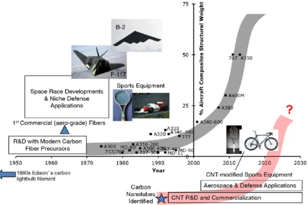
Specifically, the integration of densely-packed, vertically aligned, and high specific strength and modulus CNT reinforcements is a promising technique to enhance the prop-erties and overall performance of composite laminates for aerospace vehicles, especially when combined with existing CF-based composite technology. Over the past few decades, advances in the design and manufacture of composites have enabled the commercial aerospace industry to increase their use of these hybrid materials, as shown by the S-curves in Fig-ure 1.2 that describe the adoption of CF- and CNT-based composites in commercial air-craft.[24]With military vehicles and the defense sector requiring ultra-lightweight aerospace materials for extreme environments, the demand for carbon-based composites has grown significantly in recent years. The continual integration of these materials into aerospace vehicles now follows this S-curve trajectory, with the developmental trend of CNT com-posites paralleling that of CF-reinforced structures.[24]
In particular, high-density and high specific strength CNT architectures[1,12,25]have the potential to serve as both intralaminar reinforcement to enhance the in-plane mechanical properties of nano-engineered (hybrid) composites,[26] and as z-direction interlaminar
re-(a)SWCNT (b) Multiwall CNT (c)
5
Figure 1.1: Conceptual diagram of (a) single-walled carbon nanotube (SWCNT) and (b) multi-walled carbon nanotube (MWCNT[1]) showing typical dimensions of length, width, and inter-tube separation in MWCNTs, as presented in Ref. 13. (c) Plot of the reported mechanical properties of CNTs (here specific modulus versus specific strength), including a comparison of the mechanical properties of composite materials to other engineering materials, adapted from Ref. 14.
inforcement in composite laminates to increase Mode I and Mode II fracture toughness and interlaminar shear strength, which is achieved by ‘nanostitching’ plies together.[27–29] Recently, advances in techniques to densify vertically aligned CNT arrays into shape-engineerable and high Vf structures, such as cellular networks and pins,[30–33] also
mo-tivates their use as z-pins, a type of structural reinforcement used to enhance composite toughness via crack bridging and pullout from the matrix.[34,35] Since toughness has been predicted to increase significantly by using high Vfstructures of nanometer dimensions,[35]
aligned CNT arrays densified into cells and pins with tunable sizes and Vf’s approaching
40% are promising candidates for next-generation composite reinforcement when their ge-ometry can be accurately predicted across length scales.
As shown in Figure 1.3, integrating high specific strength and specific modulus (see Figure 1.1c) and high Vf vertically aligned CNTs can be used to enhance the properties
of a host of materials, such as nanocomposites with aerospace-grade polymer or ceramic matrices,[19,36,37]CNT films, sheets, and yarns for high-strength applications,[1]patterned nanoscale arrays for field emitters, scaffolds, electrical interconnects, and contact print-ing,[1]and large-scale aircraft composite laminates with capillary-densified CNT reinforce-ment as previously discussed.[26,28,36,38]Moreover, since the adhesion force (Fa) between a
Figure 1.2: Plot showing the adoption of advanced carbon-based composites into the total structural weight of commercial aircraft, with the upper and lower S-curves representing CF- and CNT-based structural composite materials, respectively.[19]
CNT array and its growth substrate is known to impact the capillary densification of CNT arrays,[32,33,39]with a larger Faenabling the densification of CNTs spanning several orders
of magnitude in array height (h), density, and hierarchy (as will be presented in this the-sis), further work is required to quantify and predict how Fascales with growth conditions
and particularly CNT growth time (tg), as data for modeling the physiochemical
mech-anisms governing Fa (e.g., CNT-CNT, CNT-catalyst, and catalyst-substrate interactions)
are not currently available, and must be determined. When these capabilities are realized, high-density CNT processing methods may be applied to create new CNT-polymer-fiber interface architectures towards significant improvements in the properties, scalability, cost savings, and service life of aerospace materials and related bulk (composite) structures.
Therefore, to support the design and manufacture of hierarchical CNT architectures with tunable structures and corresponding application-specific performance, it is necessary to gain a mechanistic understanding of the parameters governing the capillary densifica-tion and substrate adhesion of aligned CNT arrays. Addidensifica-tionally, to enable the
process-High-Density Aligned Nanofiber Architectures
Patterned Polymer Nanohair Arrays:
Adhesive, Self Cleaning Carbon Nanotubes: Field Emitters, Scaffolds, Printing
Carbon Nanotube Films, Carbon Nanotube Forests Sheets, Laminates, Yarns
Multifunctional Multi-scale
Figure 1.3: Application overview of aligned NFs and nanoengineered composite materials incorporating dense CNT reinforcement. High-density aligned NF architectures including polymer nanohair arrays,[40] patterned CNTs,[27] and multifunctional CNT assemblies.[1] structure-property prediction of dense and patterned CNT architectures spanning several orders of magnitude in size, a theoretical framework is required to model the evolution of CNT-substrate adhesion and morphology based on processing conditions, such as CNT growth and capillary densification procedures. To address these goals, this thesis investi-gates the interfacial phenomena crucial to the controllable fabrication of shape-engineerable nanomaterials via three studies: the morphological characterization and modeling of the capillary densification of aligned CNT architectures (cells and pins) made from 1) bulk-scale and 2) patterned CNT arrays, respectively, and 3) the CNT-substrate adhesion strength characterization as a function of tg, including process-structure-property modeling of
ad-hesion. Through these studies, this thesis develops experimentally-validated models to establish predictive process-structure-property scaling relations, with the ultimate goal to support the development of next-generation nanomaterials with enhanced performance and manufacturability.
1.2
Thesis Outline
In this thesis, the effects of processing conditions on NF structure and morphology in capillary-densified aligned CNT arrays and CNT-substrate adhesion scaling as a function of tg are explored. These findings are used to evaluate the process-structuproperty
paths of study that would enable the synthesis and densification of aligned CNT arrays with shape-engineerable morphologies and tunable substrate adhesion.
In Chapter 2, an overview of previously synthesized and capillary-densified aligned NF arrays and their observed structures and shortcomings are presented, followed by a discus-sion of parametric experimentation and elasto-capillary modeling as a promising approach towards addressing these shortcomings. Next, prior works regarding CNT-substrate adhe-sion and current limitations in understanding are discussed, and proposed methods for the experimental quantification and prediction of CNT-substrate adhesion as a function of tg
are presented. In Chapter 3, the objectives of this thesis are described, and the general approaches employed for understanding and engineering capillary-densified CNT architec-tures, CNT-substrate adhesion, and corresponding process-structure-property relations are described.
In Chapter 4, parametric experimentation of the capillary densification of bulk-scale aligned CNT arrays into cell networks with micron-scale h spanning two orders of magni-tude and two Favalues is presented. Optical microscopy and scanning electron microscopy
(SEM) are used to quantify the geometry of the resulting cell networks. Additionally, an analytical elasto-capillary model is presented to predict the cell network geometry scaling as a function of h and Fa, taking into account the solvent surface tension, initial and final
inter-CNT spacings, CNT diameter, and the effective axial elastic CNT array modulus (E). These findings are used to determine the effect of E, h, and Faon CNT densification, and
to recommend work that could further enable the fabrication of shape-tunable CNT cell networks.
In Chapter 5, parametric experimentation of the capillary densification of patterned aligned CNT arrays into solid pins and cell networks with micron-scale h in micron-scale pattern sizes (s) is presented. SEM is used to quantify the geometry of the resulting cell and pin microstructures. Additionally, an analytical elasto-capillary model is presented to predict the pin geometry scaling as a function of h and to establish the critical pattern size (scr) separating cell versus pin formation. These findings are used to determine the effect of
E, h, and s on CNT densification, and to recommend future work supporting the fabrication of high-density and shape-tunable CNT pins and patterned cell networks.
In Chapter 6, the quantification of Faand the morphological changes of mm-tall aligned
CNT arrays is presented for tg up to 80 minutes, where optical microscopy, electron
mi-croscopy, Raman spectroscopy, and tensile testing techniques are used to assess the ef-fects of tg. An analytical adhesion model describing the experimentally-determined
non-monotonic scaling of Fa with tg is presented based on contact mechanics. The findings
from this Chapter are used to quantitatively describe the effect of processing conditions on Faand to recommend future paths of study to enable the modeling of Faas a function of
dif-ferent post-processing treatments. In Chapter 7, the important conclusions of this thesis are summarized, and perspectives on these findings are provided. Next, recommendations for future studies in the areas of aligned CNT synthesis and elasto-capillary densification, mor-phology characterization and modeling, and CNT-substrate adhesion testing and prediction are made.
Chapter 2
Background
Recent developments in the growth, patterning, and densification of aligned NF arrays makes the resulting NF architectures promising for a host of multifunctional applications, such as composite reinforcement, metamaterials, field emitters, and sensors. However, the widespread use of these architectures is hindered by the performance limitations of current generation NFs and related 1D materials, as observed physical properties that are often sig-nificantly lower than theoretically predicted. As a result, inadequate modeling of NF densi-fication and NF-substrate adhesion can limit accurate material design across length scales. To create next-generation NF architectures that can access their full potential, the morpho-logical and physiochemical origins of these problems need to be determined. This Chapter will review the recent experimental and modeling developments for the capillary densifica-tion and substrate adhesion of exemplary aligned NF architectures, vertically aligned CNT arrays, with a focus on the attainable material architectures and related properties based on current processing conditions. In the remainder of this Chapter, strategies to improve upon these process-structure-property relations for aligned CNT arrays compared to the state of the art will be introduced and discussed.
The purpose of this Chapter is to provide the general background necessary for under-standing the overall motivation for the work performed in this thesis. To make sure that the presented work can be understood fully, subsequent Chapters will provide additional background information when necessary.
2.1
Aligned Nanofiber Densification via Elasto-Capillary
Self-assembly
Aligned NFs synthesized by scalable methods such as chemical vapor deposition (CVD) often have a low packing density and an inherently stochastic nature, exhibiting properties that are orders of magnitude lower than expected.[20,21,41] To overcome this, densification approaches based on biaxial mechanical forces,[19,42] stretching and alignment,[1,12] and capillary methods via evaporative self-organization of NFs[31,32,43]have been developed to increase packing density and/or form three-dimensional (3D) shape-tunable architectures out of aligned NF systems.[25,31,32,44]
In particular, scalable capillary densification techniques, which operate on the princi-ples of evaporative self-assembly,[31,32,45–47] are promising methods to create hierarchical and functional material structures without the need for cost-prohibitive cleanroom tech-niques.[25,48] This process has been used in recent years to form the aligned CNT arrays into dense 3D structures.[31,32,49] For example, vertically aligned CNT arrays can easily be densified into patterns such as solid pins and cellular networks (see Figure 2.1) for a variety of multifunctional applications. Tunable CNT Vf in the densified cell and pin walls
can be achieved by varying the processing conditions (i.e., post-growth annealing, sub-strate pre-patterning, h, and solvent properties, as shown in Figure 2.1), creating nano- to cm-scale architectures with various geometries and Vfup to 30-40% that may be described
by elasto-capillary self-organization theory.[31,33,39,50]
While these geometrically complex microstructures can be formed by growing and then densifying vertically aligned CNT arrays[32,51](see Figure 2.2 and 2.3), it is currently chal-lenging to control experimentally (and yet harder to predict theoretically) the densified CNT morphology as a function of h and s, especially without incurring the process hur-dles of cleanroom techniques. Spatially selective CNT array growth has previously been achieved by patterning catalyst layers via photo- and electron-beam-lithography[52,53](see Figure 2.3) and by using metallic layers as catalyst deactivators,[54–56]but these processes are time-consuming and cost-prohibitive at large scales. Additionally, they often produce fragile CNT arrays with synthesis-induced structural variations,[57–59]unknown Fa
affect-(f)
Capillary Densification of Nanofiber Arrays
CNT Solvent
Short nanofiber array, large pattern size,
weak nanofiber-substrate adhesion 100µm CNTs 100µm substrate substrate CNTs Cells Pins
Tall nanofiber array, small pattern size,
strong nanofiber-substrate adhesion
Figure 2.1: Overview and illustration of the capillary densification of NFs, such as aligned CNT arrays, into cell networks or pin architectures (imaged here by SEM) as a function of CNT height, pattern size, and CNT-substrate adhesion considerations.
ing capillary-mediated CNT translation,[30,31] and a low density per unit area.[60,61] To overcome these limitations, scalable processing techniques, such as simple catalyst pat-terning via mechanical scribing,[62–64]post-CNT-growth oxygen (O2) plasma treatment to
increase structural uniformity,[30] and capillary densification accounting for Fa effects are
attractive methods to create high-density, morphology-controlled bulk nanostructured ma-terials provided that new models can guide the processing towards these desired structures. Previous work has shown that it is possible to densify aligned CNT arrays into bulk-scale (long-range) cell networks via capillary forces, and early attempts at geometric scal-ing relations have been made. Figures 2.2a-d shows that the process of capillary den-sification occurs in the following manner: (a) a bulk-scale array composed of vertically aligned CNTs is grown via CVD, (b) liquid solvent is added to the array, and the formation of cracks begins during the evaporation of solvent, (c) at a later stage in the evaporation process, the shrinkage of the array commensurate with the bending and sliding of CNTs across the substrate results in the formation of open cellular structures, and (d) the final cell network is obtained after capillary densification is complete (when all of the solvent has evaporated).[65] The exemplary images shown in Figures 2.2e-h of capillary densified bulk-scale CNT arrays with an average nanotube diameter (Dcnt) of 30 nm illustrate this
result. Here, Figure 2.2f shows a side view of cellular structures formed by the evaporation of water from plasma-oxidized, vertically aligned CNTs, with the arrow depicting the cell width (w). Higher-magnification SEM images shown in Figures 2.2g-h detail these cellular structures and show how the bending of CNTs gives rise to the cell network and dense cell walls, where the CNT alignment is preserved (Figure 2.2h inset).[65]
(a) w (b) (e) (h) (c) (d) (g) (f) 101 102 101 102 CNT Height, h [µm] Cell Width, w [ µ m] w ∝ h [Ref. 65] D ∼cnt 5 − 15 nm D ∼cnt 15 − 60 nm (k) (i) h = 20 mµ (j) h = 100 mµ
Cellular Network Formation from Bulk-scale CNT Arrays via Capillary Densification
h
solvent add
Figure 2.2: Overview of experimental results for the capillary densification of bulk-scale CNT arrays into cell networks. (a-d) Schematics illustrating the formation of cellular struc-tures in vertically aligned CNT arrays of height h as presented in Ref. 65. (e-h) SEM im-ages showing the formation of cellular patterns by the evaporation of liquids from vertically aligned CNT arrays, with the arrow depicting the cell width (w), as presented in Ref. 65. (i-j) SEM images showing h dependence of the capillary-densified CNT cell networks, as presented in Ref. 66. (k) Previously reported w of CNT cells made from CNTs with diame-ters Dcnt ∼ 5 – 15 nm to 15 – 60 nm ( , and , respectively),[62,65–71] and the linear scaling
relation proposed in Ref. 65.
In this process, it has been observed that the original CNT array height (h) is a key parameter that influences the geometry of capillary-densified cell networks and may be used to predictably pattern CNTs if accurate process-structure relations can be developed. Figures 2.2i-j shows the effect of h on cell size evolution for two exemplary CNT arrays, as wider cells are formed from a 100 µm-tall CNT array compared to a 20 µm-tall CNT array.[66] While h is an important metric governing the resulting capillary-densified struc-tures, accurately predicting the geometry of CNT cellular patterns given a starting array morphology is not currently possible. Figure 2.2k shows the large variability in previously reported CNT cell sizes and a linear scaling law proposed by Ref. 65, which cannot
prop-Pins Cells Exp. Models (f) (g) s s h
Patterned CNT Array Densification: Pin and Cell Formation
(pins) Pattern Size, s CNT Height, h [µm] [ µ m]
Figure 2.3: Overview of extant experimental and modeling results for the capillary den-sification of patterned CNT arrays into cell networks and solid pins. (a-e) SEM images showing variation of structure, shape, and orientation using patterned aligned CNT arrays, as presented in Ref. 65. (f) Illustrations showing the fabrication of CNT pins by patterned CNT growth followed by self-directed capillary densification, as presented in Ref. 30. (g) Plot showing the effect of CNT microstructure dimensions on cell versus pin formation that compares analytical models to measurements of cylindrical microstructures, which were O2 plasma etched to remove the top layer of entangled CNTs prior to densification,
as adapted from Ref. 30.
erly capture the evolution of w with h (or any other geometric metrics) and may be based on non-representative assumptions of the CNT array elastic response and uncontrolled growth effects such as Fa, etc.,[30,31] leaving previous observations unexplained. To address this
limitation, new process-morphology scaling relations are needed to quantify and accurately predict the self-organization of aligned NF arrays via parametric experimentation of the capillary densification process.
Similar considerations can be made for the capillary densification of patterned CNT arrays, which are made via spatially selective CNT growth on a substrate to ensure that the starting array has smaller areal dimensions than a bulk-scale array. In this situation, inter-facial solvent-air effects at the array perimeter need to be taken into account, as they may affect the self-assembly of CNTs in the middle of the pattern. An exemplary system may be
a patterned grid of 50 µm2CNT arrays (i.e., pattern size s of 50 µm, see Figures 2.3a,f) com-pared to a uniformly grown 1 cm2bulk-scale CNT array (i.e., total substrate area coverage by CNTs, see Figures 2.2a,e), where both arrays can be grown to the same h. Figures 2.3a-e shows that control ov2.3a-er th2.3a-e structur2.3a-e, shap2.3a-e, and ori2.3a-entation of capillary-d2.3a-ensifi2.3a-ed CNT structures is possible by substrate patterning followed by densification, where 60 µm-tall CNTs were plasma-oxidized, immersed in acetone, and dried under ambient conditions.[65] Here, pin structures are obtained by the evaporation of liquids from cylindrical-patterned CNT arrays (Figure 2.3a), and the formation of directional cells is possible in patterned CNT arrays with larger s (Figures 2.3b-d). However, as s is continually decreased below a critical pattern size scr, a pin is obtained at small s due to the 1D inward bending of the
CNTs caused by capillary forces (Figure 2.3e). This scrpattern size defining cell versus pin
formation can be quantified through experimentation and modeling, and a recent attempt of this is shown in the phase diagram in Figure 2.2k,[30] where pins are obtained at small sand large h, and cells are obtained at large s and small h. Here, the discrepancies in scr
between experiments and the elasto-capillary models applied to this phenomenon[30,72,73] are quite significant and have not yet been addressed, particularly as s and h are decreased within the micron range where many CNT-based devices are desired. Similar to the w scal-ing seen in Figure 2.2k, these discrepancies are later shown in this work to be based on non-representative assumptions of the CNT array elastic response during patterned capil-lary densification, especially as related to interfacial and confinement effects due to CNTs being grown in a specific pattern size. Therefore, as in bulk-scale densification, it is nec-essary to develop more accurate process-morphology scaling relations via elasto-capillary modeling and experimentation to predict the self-assembly of aligned CNT arrays, address-ing the limitations of previous work and extendaddress-ing the use of these microstructures towards a wider range of applications.
2.2
Interfacial Substrate Adhesion in Aligned Nanofiber
Systems and Effects on Elasto-Capillary Forming
Recent advances in CNT synthesis techniques via scalable CVD, which can produce mm- to cm-tall vertically aligned CNT arrays,[2,74–76]have been supplemented by extensive char-acterization of CNT array growth, structure, and properties to support the use of CNT-based materials in commercial applications.[1,15,16] Despite this progress, a comprehensive un-derstanding of the mechanisms governing the interfacial adhesion of CNTs (and other 1D nanostructures)[77–79]to their growth substrate and/or catalyst layers (see Figure 2.4)[80–82] is still elusive, even for the much-studied CNTs synthesized via base growth CVD, for which catalyst evolution is complex and still not fully understood.[74,83,84]Both experimen-tal and modeling approaches to date have not sufficiently quantified the scaling of Fawith
processing parameters, especially tgand the resulting h values, even though these properties
are coupled and will dictate the performance of structures formed via aligned NF elasto-capillary forming. Adhesion scaling with tg is vital to the development and large-scale
integration of CNTs for applications requiring various levels of Fa, as shown in Figure 2.4.
Such applications include gecko-inspired fibrillar adhesives and MEMS devices,[85–88] contact printing,[89–92]thermal interface materials,[1,18,93,94]field emitters[81,95–97] (requir-ing strong adhesion), and CNT spinnability from a substrate to create yarns and sheets[1,98] (requiring weak adhesion). Fascaling is also crucial to the capillary-mediated densification
of aligned CNTs into dense patterned structures,[31,33,39,99] for which the role of inter-fiber adhesion has been studied,[100–103]but knowledge of substrate adhesion effects is still lacking.[30,33,39,99] Therefore, it is necessary to quantify and model these effects mecha-nistically as a function of tg to enable better understanding and control of CNT-substrate
adhesion for the versatile design and manufacturing of bulk-scale nanomaterials.
In the past, many studies have quantified h as a function of tg[56,58,104–106]and observed
the synthesis stages of steady growth (after growth initiation, usually termed nucleation), growth termination, and turbostratic carbon (t-C) deposition on the CNT walls at long tg
(as shown in Figure 2.5). These stages are marked by an h increase, an abrupt cessation in further h increase followed by a plateau, and an increase in CNT wall thickness (a),
![Figure 1.1: Conceptual diagram of (a) single-walled carbon nanotube (SWCNT) and (b) multi-walled carbon nanotube (MWCNT [1] ) showing typical dimensions of length, width, and inter-tube separation in MWCNTs, as presented in Ref](https://thumb-eu.123doks.com/thumbv2/123doknet/14198293.479471/33.918.150.776.107.330/figure-conceptual-diagram-nanotube-nanotube-dimensions-separation-presented.webp)