Drop impact and capture on a thin flexible fiber
The MIT Faculty has made this article openly available. Please share
how this access benefits you. Your story matters.
Citation
Comtet, Jean, Bavand Keshavarz, and John W. M. Bush. “Drop
Impact and Capture on a Thin Flexible Fiber.” Soft Matter 12.1
(2016): 149–156.
As Published
http://dx.doi.org/10.1039/C5SM02037A
Publisher
Royal Society of Chemistry
Version
Author's final manuscript
Citable link
http://hdl.handle.net/1721.1/106678
Terms of Use
Creative Commons Attribution-Noncommercial-Share Alike
Jour
nal
Name
Drop impact and capture on a thin flexible fiber
†
Jean Comtet,∗aBavand Keshavarz,aand John W.M. Bushb
When a drop impacts a thin fiber, a critical impact speed can be defined, below which the drop is entirely captured by the fiber, and above which the drop pinches-off and fractures. We discuss here the capture dynamics of both inviscid and viscous drops on flexible fibers free to deform following impact. We characterize the impact-induced elongation of the drop thread for both high and low viscosity drops, and show that the capture dynamics depends on the relative magnitudes of the bending time of the fiber and deformation time of the drop. In particular, when these two timescales are comparable, drop capture is less prevalent, since the fiber rebounds when the drop deformation is maximal. Conversely, larger elasticity and slower bending time favor drop capture, as fiber rebound happens only after the drop has started to recoil. Finally, in the limit of highly flexible fibers, drop capture depends solely on the relative speed between the drop and the fiber directly after impact, as is prescribed by the momentum transferred during impact. Because the fiber speed directly after impact decreases with increasing fiber length and fiber mass, our study identifies an optimal fiber length for maximizing the efficiency of droplet capture.
1
Introduction.
The interaction of droplets with slender structures is ubiquitous in both nature and technology. In applications such as fog harvest-ing1and air filtration2,3, forcing aerosols through fiber arrays al-lows for partial recovery of the liquid phase. Such recovery mech-anisms can also be found in nature: plants like desert grass4and cactii5can efficiently harvest fog droplets, as can spider webs6. The interaction of droplets with flexible fibers also arises on the integument of insects, and so is critical for the sustenance of life at the millimeter scale7; for example, rain droplets can have
dra-matic consequences on the flight of mosquitos8. Slender struc-tures and fibers are often deformable; nevertheless, the influence of structure flexibility on the capture of droplets has received very little attention.
The problem of drop impact on thin elongated structures, namely rods or fibers, was first examined by Hung and Yao9 and Patel et al.10. Lorenceau et al. quantified the critical
ve-locity threshold between capture and fragmentation for inviscid droplets impacting a fixed fiber (Figs. 1b; 2)11. For inviscid drops, V∗was shown to depend on the relative size of the drop and fiber, and to increase when the impact occurs on an inclined fiber12. Numerous other studies have been devoted to the optimization of fog harvesting structures, via alteration of mesh geometry13, sur-face chemistry14–16 and fiber microstructure5,6,17,18, with little
a
Department of Mechanical Engineering, Massachusetts Institute of Technology, Cam-bridge, MA 02138, USA.∗E-mail: [email protected]
b
Department of Mathematics, Massachusetts Institute of Technology, Cambridge, MA 02138, USA
attention being given to the initial capture stage.
To the best of our knowledge, the influence of fiber flexibility on the efficiency of capture of impacting droplets has yet to be considered. It is well-known that droplets can significantly alter the equilibrium shape of thin fibers even in static situations19,20. In many cases of man-made and natural structures, the deforma-bility of the structure may also play a critical role in droplet capture. Indeed, flexible substrates21and membranes22,23 have been shown to delay or reduce splashing and jetting during drop impact, and can also significantly alter the drop fragmentation dynamics24. Flexible beams have been used to measure forces of
impacting drops25and the surface chemistry of the beams has a significant impact on energy transfer during impact26. In most of these studies, structural flexibility seems to act as a damper; how-ever, it may also act to feed energy back into the system, as may arise during drop impact and fragmentation on plant leaves24.
We first describe the relevant timescales and lengthscales at play during impact, and how they are expected to interact. We then consider the impact of a drop on a rigid fiber and study the resulting dynamics for both high and low viscosity drops. Finally, we consider the role of fiber flexibility on droplet capture.
2
Physical Picture.
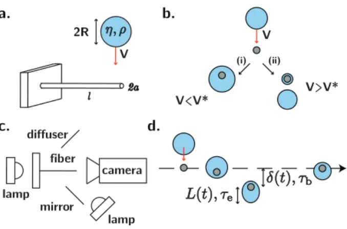
We consider here the effects of fiber flexibility and fluid viscosity on drop capture. Fig. 1a presents the typical impact configura-tion, where droplets of radius R, density ρ, surface tension σ , volume Ω = 4πR3/3and viscosity η impact with velocity V on the
tip of a fiber of length l and radius a, clamped at one end and free to bend at the other.
b. d. mirror fiber lamp camera diffuser lamp V<V* V>V* c. V l 2a 2R a. (i) (ii) V
Fig. 1 (a) Typical impact configuration. A drop of radius R, viscosity η,
and density ρ impacts the tip of a fiber of radius a and length l, clamped at one end. The fiber may deform in response to impact. (b) For a
centered impact at speed V , a critical capture speed V∗can be defined.
(i) When V < V∗, the drop elongates, recoils and gets caught on the fiber.
(ii) When V > V∗, the drop pinches off and fractures. (c) Schematic of
the experimental set-up, with the high-speed camera and two hallogen lamps. A mirror allows the simultaneous observation of both front and side views of the impact.(d) When the fiber is free to bend under impact,
it is deflected by a typical distance δ (t) over a characteristic bending time τb, while the drop deforms an amount L(t) over a characteristic elongation
time τe.
We consider the limit where the fiber radius is small relative to drop radius, and restrict ourselves to the case for which the center of mass of the drop is aligned with the center of the fiber before impact (Fig. 1b). This configuration allows us to define a critical capture speed11, which we denote by V∗. For impact speeds V < V∗, the drops will be caught on the fiber (i), and for V > V∗, the drops will fracture and pinch-off (ii). Fig. 2 shows typical impact sequences for the case of (i) capture and (ii) fracture. The fiber can substantially deform during impact, thus potentially playing an important role in the capture process in general and the critical impact speed V∗in particular. Changing the fiber length l allows us to systematically change the elastic response of the fiber. In the case of droplet capture, the drop hangs below the fiber, at an equilibrium offset length Leq∼ ρgR4/σ a set by a balance between
surface tension and drop weight. In the case of droplet fracture, some fraction of the drop remains on the fiber.
We first consider the case of a rigid fiber. As the drop hits the fiber, one expects inertia and gravity to favor drop fracture and escape; viscosity and surface tension to favor capture. The relative magnitudes of the two capture forces is prescribed by the Ohnesorge number, which we define here as Oh = 3η/√ρ σ R (where the factor 3 is Trouton’s ratio and characterizes the ex-tensional viscosity of a thread), while the relative magnitude of the forces favoring escape and fracture is characterized by the Froude number Fr = V2
/gR & 1. Following impact, the drop elon-gates to a length L(t) over a characteristic elongation timescale τe
(Fig. 1d; Fig. 2, third frame). For Oh 1, one expects τeto
corre-spond to a typical inertia-capillary timescale τic∼
p
ρ R3/σ ; when Oh 1, one expects τeto correspond to the timescale of viscous
momentum diffusion in the drop τv= ρR2/3η, and drop recoil to
arise over the typical viscocapillary time τvc= 3ηR/σ . Relevant
timescales in the impact process are summarized in Table 1. We then consider drop impact on flexible fibers. Upon impact, we expect the fiber to deform by an amount prescribed by the transfer of momentum between the drop and the fiber during im-pact over a typical natural bending time τb≈ l2q
ρfπ a2/EIwith
lthe fiber length, ρf its density, E the Young modulus, a the fiber
radius and I the area moment of inertia. Since fiber bending stores elastic energy, one expects that capture should in general be favored. However, as we shall see, elasticity may also feed en-ergy back into the system at a critical time, thereby encouraging droplet fracture.
Table 1 Relevant Timescales
Convective time τc R/V
Inertio-capillary time τic
p ρ R3/σ
Viscous diffusion time τv ρ R2/3η
Visco-capillary time τvc τic2/τv= 3ηR/σ Bending time τb τb= l2 p ρfπ a2/EI Ohnesorge number Oh = 3η/√ρ σ R Oh 1 Oh> 1 Elongation time τe τic τv Recoil time τr τic τvc
3
Experiments
3.1 Experimental MethodA schematic of the experimental set-up is presented in Figs. 1a and 1c. Small droplets of radius R between 0.75 and 1 mm are dropped from a syringe placed above the fiber. For each exper-imental condition, the height is gradually adjusted to determine the velocity threshold V∗, defined in Fig. 1b, below which the entire drop is captured. Impact speeds are measured via video analysis. A mirror placed at 45° to the fiber axis, allows for the simultaneous observation of both the front and side views of the impact using a single high-speed camera Phantom Miro 320S. A typical impact sequence is shown in Fig. 2. We used frame rates up to 18,000 images per second and a typical exposure time be-tween 5 and 50 µs. The fluids used were silicon oils of viscosity ranging from 1 to 800 cPs, with density ρ = 970 kg/m3, and
sur-face tension σ = 21 mN/m. These oils completely wet the fiber. Fibers are made of nitinol, with fiber lengths ranging from 5 to 150 mm, allowing us to tune their elastic response. For lengths longer than a few centimeters, the fibers bend under their own weight. In this case, we alter the tilt angle of the substrate so that impact always occurs on a horizontal fiber tip. Impacts occur 2-3 drop radii from the fiber tip, so that the local geometry of impact is effectively the same for all experiments. Image analysis was carried out using ImageJ.
3.2 Capture on a fixed fiber
We first consider the case of stiff fibers and investigate the influ-ence of liquid viscosity on the droplet capture process. A fiber of radius a = 127 µm is clamped at both edges so that fiber flexibil-ity does not play a role (inset, Fig. 3). Droplets of fixed radius R= 850µm are dropped from a nozzle placed directly above the fiber, at heights ranging from 1 mm to 1 meter. We plot in Fig. 3 the dependence of the critical capture speed V∗on the drop
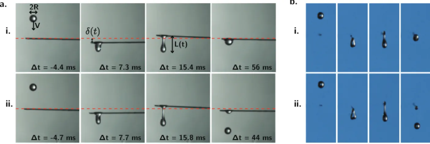
vis-i. ii. 2R V L(t) i. ii. a. b. Δt = -4.4 ms Δt = 7.3 ms Δt = 15.4 ms Δt = 56 ms Δt = -4.7 ms Δt = 7.7 ms Δt = 15.8 ms Δt = 44 ms
Fig. 2 Side (a) and front (b) view of the typical impact sequence of a drop of radius R = 752 µm on a fiber of radius a = 127 µm and length l = 4.5
cm. The horizontal dotted red line represents the equilibrium position of the fiber tip. In this sequence, the fiber is deflected by a distance δ (t), first downward (red arrow on 2nd frame) and then upward (red arrow on 3rd frame). Upon impact, the drop is stretched by an amount L(t).(i) For impact
speeds smaller than the critical capture speed (V = 0.846 m/s < V∗), the drop is captured. (ii) For V = 0.922 m/s > V∗, the drop pinches-off and
fractures.
cosity (lower axis) and the Ohnesorge number Oh = 3η/√ρ σ R that characterizes the relative importance of viscous and capil-lary forces in the capture process (upper axis). For low Oh, V∗ is independent of viscosity, consistent with the inviscid case de-scribed by Lorenceau et al.11(horizontal dotted line, Fig. 3). The over-estimation of the critical capture speed by the model could result from the drop radius being close to the maximal radius of static drops on fibers. For Oh > 1, the capture threshold increases linearly with fluid viscosity, indicating that viscous dissipation fa-vors droplet capture. In this case, the critical speed V∗ is pre-scribed by a balance between inertial and viscous effects. Specif-ically, we expect viscous stresses to overcome drop inertia when ρV2/R ∼ 3ηV /R2. Defining the Reynolds number as Re ≈ ρ RV
3η ,
our experiments indicate a capture threashold of Re ≈ 1.8. This condition can equivalently be deduced by balancing the drop con-vective time R/V with the viscous diffusion time τv= ρR2/3η.
To understand the dynamics of impact, we show in Fig. 4 the typical elongation dynamics of drops impacting fibers in the two limits Oh 1 and Oh > 1. Following impact, the drop is stretched and elongates over a typical elongation timescale τe, before
ei-ther (i) recoiling over a time τr or (ii) fracturing. For Oh 1,
the elongation dynamics is symmetric, as both elongation time τe
and recoil time τrscale as the typical inertia-capillary or Rayleigh
timescale τic∼
p
ρ R3/σ . When Oh 1, the drop speed is first reduced over a viscous timescale τv= ρR2/3η; the thread then
re-coils with a characteristic visco-capillary time τvc= 3η/σ R. In this
case, the elongation dynamics is highly asymmetric, as the ratio between the recoil and elongation times, τr/τescales as Oh2> 1.
3.3 Fiber deformation upon impact
We now study the case where the fiber is free to bend and de-form in response to impact. We use fibers of radius a = 127 µm and a = 63.5 µm. When studying impacts of low viscosity drops (Oh 1), we increased the radius of the outer extremity of the fiber to 215 µm, allowing for larger capture speeds that could be
1 10 100 1000 V 2R 2a capture V<V* fracture V>V* V* (m/s) 10-2 10-1 100 101 1 1 Viscosity (cSt) Oh 0.1 1 10
Fig. 3 Impact on a rigid fiber (inset). Variation of the critical capture
speed V∗(m/s) with drop viscosity η (lower axis) and Ohnersorge number Oh= 3η/√ρ σ R (upper axis). The dashed line is the expected capture speed for Oh 1 using the expression from Lorenceau et al.11. For
Oh≥ 1, V∗ increases linearly with viscosity. Drop radius is R = 850 µm
and fiber radius a = 127 µm. Error bars characterize the uncertainty in the impact speed prevalent at low speeds.
measured more precisely. The typical time evolution of the fiber ( red) and the drop (green) deformations following impact are shown in Fig. 5a. We denote by δ (t) the fiber displacement, and L(t)the drop elongation relative to the fiber.
3.3.1 Fiber oscillations
Following impact, the fiber starts to oscillate with a characteristic time scale τb (Fig. 5a). In Fig. 5b, we plot the variation of this
bending timescale τb with fiber length l and find τb∼ l2, as is
a.
i. recoil
ii. fracture
x t
Oh>1
LeqOh<<1
Leqb.
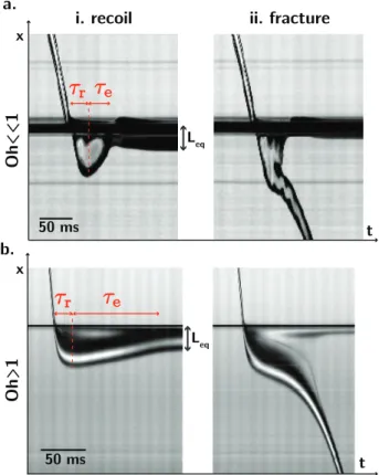
50 ms t x 50 msFig. 4 Kymograph (spatiotemporal diagrams) of impact on a rigid fiber.
Vertical slices of video images of 1 pixel width passing through the drop centerline are placed side by side with time increasing from left to right.
(a) η = 1 cPs (Oh << 1) and (b) η = 190 cPs (Oh > 1). The drop elongates
for a time τe, and then either (i) recoils over a time τrto its equilibrium
offset length Leq, or (ii) fractures. For Oh 1, τe∼ τris set by the
inertia-capilary time τic∼
p
ρ R3/σ , while for Oh > 1, τe∼ ρR2/3η and τr∼ 3ηR/σ
(Cf. Table 1). τb= 2π β2 s ρfπ a2 EI l 2 (1)
where β = 1.875 for the first mode of oscillation, E = 64 GPa the beam’s Young Modulus, I = πa4/4 the moment of inertia,
ρf = 6450 kg/m3 the beam density. This scaling is consistent
with the fact that drop weight can be neglected compared to fiber weight, and does not affect the oscillatory dynamics of the fiber. We note that for the longest fibers, higher modes of vibration are also excited, but the timescale of the first mode remains domi-nant (see e.g. Fig. 8c). While fiber oscillations are damped, the drop capture or fracture occurs during the initial oscillations of the fiber; consequently, we may safely neglect this damping.
3.3.2 Initial fiber speed
The two other critical parameters for impact on flexible fibers are the oscillation amplitude δ0after impact (red curve, Fig. 5a),
and the initial fiber speed Vfiberdirectly after impact (red arrow,
Fig. 5a). Neglecting higher modes of oscillation and fiber damp-ing, we express the fiber displacement δ (t) as:
δ (t) = δ0sin(2πt/τb) = Vfiberτb 2π sin(2πt/τb) (2) b. a. l (cm) 1 10 10-3 10-2 10-1 100 1 2 Bending Time (s) 50 ms 2 mm t x
Fig. 5 Impact on a flexible fiber. (a) Kymograph for the impact of a
viscous drop (η = 100 cst) of speed V on a fiber of radius a = 127 µm and length l = 5 cm. The fiber starts oscillating with a typical timescale τb,
amplitude δ0and initial velocity Vfiber.(b) Variation of the typical bending
timescale τbwith fiber length L. We find τb∼ l2, as expected on the basis
of Eq. (1). Black points: impacts for Oh 1, with a = 63.5 µm and a fiber tip of 250 µm. Red points: impacts for Oh > 1, with a = 127 µm.
where Vfiber= ˙δ (0) = 2π δ0/τb. In Figs. 6a and c we plot Vfiberas
a function of the drop impact speed V . We find markedly differ-ent behaviour, according to the drop viscosity. For low viscosity drops (Fig. 6a), the initial fiber speed is largely independent of drop impact speed for impacts leading to fracture (black points). Conversely, for viscous drops, initial fiber speed is proportional to drop impact speed (Fig. 6c).
To rationalize this behaviour, let us consider the processes ac-companying impact. Because convection time R/V is typically small relative to the fiber response time τb, fiber elasticity can be
neglected when considering the impact dynamics25, and we can express the transfer of momentum between the drop and the fiber during impact as follows:
MeffVfiber∼ F∆t (3)
where Meffis the effective fiber mass, F the force applied by the drop to the fiber and ∆t the interaction time. Considering clamped
r = V fib er /V 0 200 400 600 800 1000 1200 1400 0 100 200 300 400 500 600 700 100 cst 150 cst 0 500 1000 1500 0 20 40 60 80 100 120 Vfib er (mm/s) drop speed V(mm/s) a. c. capture fracture b. d. V fib er (mm/s) Vfib er (mm/s) drop speed V (mm/s) 20 40 60 80 100 120 140 0.16 0.18 0.2 0.22 0.24 0.26 0.28 0.3 0.32 0.34 0.36 Fiber Length (mm) 40 60 80 100 120 140 50 60 70 80 90 100 110 Fiber Length (mm)
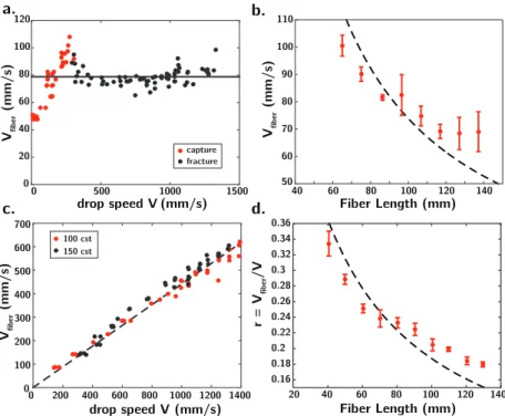
Fig. 6 Momentum transfer during impact. Variation of post-impact initial fiber speed Vfiberwith drop impact speed V .(a-b) Low viscosities drops (η = 1
cPs), fiber radius is a = 63.5 µm and radius of the fiber tip is 215 µm. (a) Fiber length l is 8 cm. For impact speeds leading to drop fracture (black
points), Vfiberis independent of drop impact speed V .(b) Vfiberdecreases with increasing fiber length and fiber mass, according to Eq. (4).(c-d) High
viscosities drops (η > 100 cPs), fiber radius is a = 127 µm. (c) Vfiberis proportional to V and independent of liquid viscosity. Fiber length is 60 µm.(d)
The coefficient of proportionality r = Vfiber/Vdecreases with increasing fiber length according to Eq. (5). In(b) and (d), error bars correspond to one
typical standard deviation. The dashed lines are fits to the data points (see text for details).
boundary conditions and impact on the tip, the effective fiber mass is ρfπ a2l/3, with l the fiber length, a the fiber radius and
ρf the fiber density25. For simplicity, we take F ∼ ηRV in both
low and high viscosity limits.
For low viscosities, when the impact speed is too large for the drop to be caught on the fiber, the drop crosses the fiber with a contact time ∆t ∼ 2R/V inversely proportional to the impact speed. Rewriting Eq. (3), this condition predicts an initial fiber speed independent of the drop impact speed, as is apparent in the black points of Fig. 6a:
Vfiber∼η R
2
Meff
(4) As expected from Eq. (4), Vfiberdecreases with increasing fiber
length, that is, larger effective fiber mass Meff (Fig. 6b). The dashed line in Fig. 6b is the best fit to the experimental points, using the expression Vfiber≈ α ·8πη(2R)2V/(ρfπ a2l/3), with α ≈ 3 a fitting parameter. For the lowest impact speeds, where the drop is captured by the fiber (Fig. 6a, red points), Eq. (4) breaks-down due to an increase in the interaction time between the fiber and the drop, which leads to enhanced momentum transfer. In this case, for which ∆t ≈ τic, fiber speed is expected to grow linearly
with drop impact speed: Vfiber∼ ηRV /Meff·p
ρ R3/σ (Fig. 6a, red points).
For large viscosities, whether impact leads to capture or frac-ture, the drop initially "sticks" to the fiber, transfering momentum to the fiber for a time ∆t ∼ ρR2/3η corresponding to the
character-istic time of viscous penetration of the drop on the fiber. Rewriting equation (3), we obtain:
Vfiber∼
ρ R3V Meff
(5) In this regime, the initial fiber speed for both capture and fracture is proportional to the drop impact speed, and momentum transfer is independent of viscosity, as is evident in Fig. 6c. Eq. (5) can also be understood by assuming an inelastic collision between the drop and fiber, which leads to (m + Meff)Vfiber∼ mV where
m∼ ρR3is the drop mass. We denote by r = V
fiber/V the relative
magnitudes of these two velocities. As expected from Eq. (5), r decreases with increasing fiber length, or equivalently increasing fiber mass Meff(Fig. 6d). The dashed line in Fig. 6d is the best fit to the experimental points, using the expression r ≈ 1/(1 + β · ρfπ a2l/(4πρR3)), with β ≈ 4 a fitting parameter.
3.4 Capture on a flexible fiber
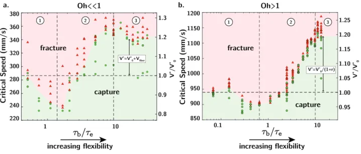
With this physical picture in mind, we now study how the cap-ture criteria for drops changes with fiber elasticity. We report in Fig. 7 the variation of the critical capture velocity V∗with fiber flexibility, for both small (7a) and large (7b) Ohnesorge numbers as a function of the ratio of bending to elongation times τb/τe,
which necessarily increases with fiber flexibility. The black hori-zontal dashed line indicates the capture speed in the limit of rigid fibers, which we denote by V0∗. We recall that for Oh 1, the elongation time τescales as the inertio-capillary time of the drop
0.1 1 10 Critical Speed (mm/s) 850 900 950 1000 1050 1100 1150 1200 220 240 260 280 300 320 340 360 380 1 10 Critical Speed (mm/s) V */V * 0 V */V * 0 1.0 0.9 0.8 1.1 1.2 1.3 1.00 0.95 1.05 1.10 1.15 1.20 1.25
increasing flexibility increasing flexibility
V*=V* 0+Vfiber V*=V* 0/(1+r) Oh<<1 Oh>1 1 2 3 1 2 3 a. b. fracture capture fracture capture
Fig. 7 Variation of critical capture speed V∗with τ
b/τe, the ratio of bending and elongation timescales. The horizontal dashed line represents the
experimentally determined capture speed on a rigid fiber V0∗. Red triangles: impacts leading to fracture. Green dots : impacts leading to capture. (a)
For Oh 1, τe=
p
ρ R3/σ ≈ 15 ± 1.5 ms. (b) For Oh > 1, τe= ρR2/3η ≈ 13.5 ± 1.5 ms. In zone 1, the critical capture speed V∗decreases with increasing
flexibility, being uniformly less than the capture speed on rigid fibers V0∗. Increasing flexibility then leads to larger capture speeds (zone 2), V∗> V0∗, up to a point where V∗tends to plateau (zone 3). Drop radius R is 820 µm. In the low viscosity case(a), V0∗is within 10% of the expression predicted by Lorenceau et al.
τic=
p
ρ R3/σ (Fig. 4a), while for Oh 1, τescales as the viscous
timescale τv∼ ρR2/3η (Fig. 4b).
To understand the phase diagrams of Fig. 7 in term of the interaction of the drop and fiber, we present in Fig. 8 typical ky-mographs of capture events for Oh 1. For short fibers (Fig. 8a), small fiber oscillations arise over a characteristic time τb short
relative to the characteristic elongation time τe of the drop. In
this limit we expect to recover the static critical capture condi-tion (Fig. 8a, τb< τe,V∗≈ V0∗). As fiber flexibility increases, we
observe a decrease in the critical capture speed (Fig. 7, zone 1), which reaches a minimum when the elongation and bending timescales are of the same order. In this critical case, the de-formed fiber begins to rebound just as the drop is reaching its maximal length, thus precipitating fracture at a speed lower than in the static fiber case (Fig. 8b, τb∼ τe, V∗< V0∗). Thereafter, V∗
then increases progressively with flexibility, and exceeds that on a stiff fiber V0∗(Fig. 7, zone 2). In this regime, some of the kinetic energy of impact is stored as elastic energy by the fiber, and is restored as the drop recoils (τb> τe, V∗> V0∗).
Finally, for long fibers, or large bending period (Fig. 8c, τb&
10 · τe, Zone 3) the critical capture speed saturates. In this limit,
fiber oscillations are decorrelated from the drop temporal dynam-ics, and the fiber is carried with the drop at its initial velocity Vfiber, independent of fiber flexibility (see Fig. 6). This long-fiber
limit leads to a maximal increase in the capture speed; since the fiber simply follows the drop, the initial elongation rate of the drop ˙L(0) = V −Vfibercan be greatly reduced relative to that
aris-ing in the static fiber case. For Oh 1, the initial fiber speed Vfiber
is independent of drop impact speed (Fig. 6a), and we expect the capture speed V∗to be increased by an amount Vfiberrelative to
that on a stiff fiber V∗
0. For Oh 1, the ratio r = Vfiber/Vdropis
con-stant and we thus expect V∗= V0∗/(1 − r). These two predictions are consistent with our experimental data, and show the critical importance of momentum transfer between the drop and the fiber in optimizing capture efficiency.
4
Discussion
We have investigated the dynamics of drop impact on flexible fibers, and examined how the critical capture speed depends on both drop viscosity and fiber flexibility. Surface tension and vis-cosity are the two forces favoring drop capture, and their rel-ative magnitude is prescribed by an Ohnersorge number Oh = 3η/√ρ σ R. We first characterized the elongation dynamics of a drop impacting a rigid fiber for high and low Oh. For Oh 1, we showed that the drop elongates and recoils symmetrically with a typical inertia capillary timescale τic∼
p
ρ R3/σ (Fig. 4a). When Oh> 1, drop elongation is asymmetric: the thread is first damped over a viscous timescale τv= ρR2/3η and then recoils with
char-acteristic viscocapillary time σ R/3η (Fig. 4b). For Oh > 1, balanc-ing the viscous time τvwith the convective time R/V leads to a
simple capture condition Re . 1.8 (Fig. 3).
When the fiber is free to bend, the impacting drop may excite oscillations of the fiber at its natural period τb, with an amplitude
set by momentum transfer during impact (Fig. 5). For large vis-cosities, the impact is inelastic, and the initial fiber speed Vfiberis
proportional to the drop speed V . For low viscosities, the contact time varies inversely with the impact speed, leading to an initial fiber speed Vfiberthat is independent of drop speed V (Fig. 6). In
both cases, momentum transfer is independent of fiber elasticity, but depends on the fiber length.
The ratio of the drop elongation timescale τe and the fiber
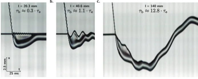
a. b. c. 2.5 mm 25 ms x t l = 20.3 mm l = 40.6 mm l = 140 mm
Fig. 8 Experimental kymographs for drop impact on a flexible fiber in the Oh > 1 case. (a) Short fiber. Fiber oscillations are small in amplitude and
arise over a timescale short relative to the typical drop deformation time τe. (b) Intermediate flexibility. The fiber rebounds as the drop achieves its
maximum deformation (Fig. 7, transition 1-2).(c) Long fibers. The fiber follows the drop, and rebounds only once the drop has recoiled, thus increasing
the capture speed relative to the rigid-fiber case (Fig. 7, zone 3).
criteria. For both viscous and inviscid drops, the critical capture speed varies non-monotically with fiber flexibility. In particular, the capture speed V∗ reaches a minimum when the fiber’s
bend-ing time is comparable to the drop’s elongation time, as the fiber begins to rebound just as the drop is reaching its maximal length, thus precipitating fracture. Here, the flexible structure does not act strictly as a damper, but instead promotes fragmentation.
For larger flexibility, the fiber begins to rebound only after the drop has started recoiling, leading to an increase in the critical capture speed. Beyond a critical flexibility, the fiber temporal dynamics occurs over a time much larger than the fiber elonga-tion time, and the critical capture speed plateaus. In this limit, the fiber follows the drop with a constant speed, prescribed by the momentum transferred during impact, that decreases with increasing fiber length and fiber mass. We can thus define an op-timal fiber length for capture. Specifically, we require that the bending time τb∼ l2q
ρf/Ea2be large enough for fiber rebound
to occur after drop recoil, and that the fiber mass Meff∼ ρfa2lbe
small enough to allow maximal momentum transfer between the drop and the fiber, thereby reducing their relative speed. The fiber radius a and Young Modulus E are thus critical parameters in at-taining the regime τb& 10 · τewhile maintaining a low fiber mass
(τe≈ 5 ms for a 1 mm water drop). We note that locally
increas-ing the radius at the point of impact allows for large momentum transfer during impact, without reducing the capture efficiency associated with large drop-to-fiber aspect ratio11.
Droplet capture can thus be significantly enhanced by large fiber flexibility. This finding informs applications in which flexible structures are used to recover aerosols, as it provides a straight-forward way to boost droplet recovery rates. Finally, we note that fiber surface chemistry and roughness will also affect criteria for droplet capture on flexible fibers, as will the detailed geometry of impact. Such effects are left for future consideration.
5
Acknowledgements
We thank Pedro Reis for providing the nitinol fibers. Jean Comtet thanks Peko Hosoi for her support.
References
1 O. Klemm, R. S. Schemenauer, A. Lummerich, P. Cere-ceda, V. Marzol, D. Corell, J. van Heerden, D. Reinhard, T. Gherezghiher, J. Olivier et al., Ambio, 2012,41, 221–234. 2 P. Contal, J. Simao, D. Thomas, T. Frising, S. Callé, J.
Appert-Collin and D. Bémer, Journal of Aerosol Science, 2004, 35, 263–278.
3 T. Frising, D. Thomas, D. Bemer and P. Contal, Chemical
En-gineering Science, 2005,60, 2751–2762.
4 A. Roth-Nebelsick, M. Ebner, T. Miranda, V. Gottschalk, D. Voigt, S. Gorb, T. Stegmaier, J. Sarsour, M. Linke and W. Konrad, Journal of The Royal Society Interface, 2012, rsif20110847.
5 J. Ju, H. Bai, Y. Zheng, T. Zhao, R. Fang and L. Jiang, Nature
communications, 2012,3, 1247.
6 Y. Zheng, H. Bai, Z. Huang, X. Tian, F.-Q. Nie, Y. Zhao, J. Zhai and L. Jiang, Nature, 2010,463, 640–643.
7 J. W. Bush, D. L. Hu and M. Prakash, Advances in Insect
Physi-ology, 2007,34, 117–192.
8 A. K. Dickerson, P. G. Shankles, N. M. Madhavan and D. L. Hu,
Proceedings of the National Academy of Sciences, 2012, 109,
9822–9827.
9 L. Hung and S. Yao, International journal of multiphase flow, 1999,25, 1545–1559.
10 P. D. Patel, E. S. Shaqfeh, J. E. Butler, V. Cristini, J. Bławzdziewicz and M. Loewenberg, Physics of Fluids
(1994-present), 2003,15, 1146–1157.
11 É. Lorenceau, C. Clanet and D. Quéré, Journal of colloid and
12 K. Piroird, C. Clanet, É. Lorenceau and D. Quéré, Journal of
colloid and interface science, 2009,334, 70–74.
13 H. Andrews, E. Eccles, W. Schofield and J. Badyal, Langmuir, 2011,27, 3798–3802.
14 K.-C. Park, S. S. Chhatre, S. Srinivasan, R. E. Cohen and G. H. McKinley, Langmuir, 2013,29, 13269–13277.
15 B. S. Lalia, S. Anand, K. K. Varanasi and R. Hashaikeh,
Lang-muir, 2013,29, 13081–13088.
16 L. Zhai, M. C. Berg, F. C. Cebeci, Y. Kim, J. M. Milwid, M. F. Rubner and R. E. Cohen, Nano Letters, 2006,6, 1213–1217. 17 Z. Huang, Y. Chen, Y. Zheng and L. Jiang, Soft Matter, 2011,
7, 9468–9473.
18 Y. Hou, Y. Chen, Y. Xue, Y. Zheng and L. Jiang, Langmuir, 2012,28, 4737–4743.
19 C. Duprat, S. Protiere, A. Beebe and H. Stone, Nature, 2012,
482, 510–513.
20 S. Protiere, C. Duprat and H. Stone, Soft Matter, 2013, 9, 271–276.
21 S. Mangili, C. Antonini, M. Marengo and A. Amirfazli, Soft
Matter, 2012,8, 10045–10054.
22 R. E. Pepper, L. Courbin and H. A. Stone, Physics of Fluids, 2008,20, 082103.
23 J. Field, J. Dear and J. Ogren, Journal of Applied Physics, 1989, 65, 533–540.
24 T. Gilet and L. Bourouiba, Journal of The Royal Society
Inter-face, 2015,12, 20141092.
25 D. Soto, A. B. De Larivière, X. Boutillon, C. Clanet and D. Quéré, Soft matter, 2014,10, 4929–4934.
26 S. Gart, J. E. Mates, C. M. Megaridis and S. Jung, Physical